
Here are all 194 Energy Conversion questions asked in UPSC Electrical Engineering Optional Paper I from 1995 to 2026, arranged under the 5 topics of the official syllabus. Within each topic the latest questions come first.
Each question ends with a code such as [2024/15m/3b] – the year, the marks, the word limit (where UPSC set one) and the question number in the paper.
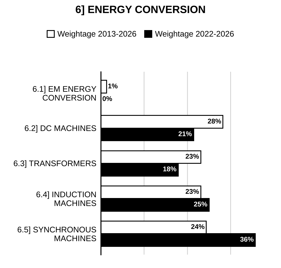
6.1] Electromechanical energy conversion
10 questions
A magnetic circuit shown below consists of two sections of Al-ni-co-5 of length embedded in a core of high permeability (). The cross-sectional areas of core, Al-ni-co-5 and air-gap are equal. The air-gap length ‘g’ = 0.2 cm has neglible fringing effect.
[Figure: Figure 8(c-1): Rectangular magnetic core of infinite permeability (μ → ∞) with two Al-ni-co-5 sections of length (cross-section ), one in the top limb and one in the bottom limb; the right limb contains an air gap of length g (permeability , area ); , ]
If Al-ni-co-5 material B-H curve in second quadrant is linearly approximated, it can be given as below.
[Figure: Figure 8(c-2): Linearised second-quadrant B-H curve of Al-ni-co-5 (B in T against H in kA/m, H axis marked −50, −40, −30, −20, −10, 0; B axis marked 0.5 and 1.0): a steep straight line (“Linear”) from at B = 0 up to B = 1.0 T at H = −40 kA/m (dashed lines mark this point), then a second straight line (“Linear”) of small slope from that point to the B axis at H = 0, meeting it above 1.0 T (intercept value not labelled; about 1.25 T by scale)]
Determine the slope of load line for the problem and hence determine the value of flux density () in the air-gap. [2019/10m/8c]
A 2-pole full pitch concentrated coil of n turns is placed in the stator of an electric machine in two slots diagonally opposite to each other. A permanent magnet 2-pole rotor is rotating at N rpm producing a flux per pole with its flux density sinusoidally varying in space in the airgap. At time rotor field axis is in line with the stator coil axis. Write an expression for the flux linking the stator coil as a function of time. Derive from this expression the r.m.s. value of the voltage induced in the stator coil. Draw the waveform of flux linkage and voltage generated. Write expression for frequency of voltage in terms of speed. [2012/12m/5c]
A 3-phase, 50 Hz, 16 pole generator with star connected windings has 144 slots with 10 conductors per slot. The flux/pole of 24.8 mWb is sinusoidally distributed. The coil is full pitched. Find the line emf. [2004/15m/3b(ii)]
A full-pitched coil having N turns rotates with an angular velocity of rad/sec with respect of field flux. Obtain an expression for the flux Linkages with the coil as a function of time t. Derive there from an expression for the emf generated in the coil. Discuss about the two components of the emf expression so obtained. [2003/10m/1c(i)]
Show that, in case the field flux is time-invariant, the generated emf lags by 90° the flux that generates it. [2003/10m/1c(ii)]
Figure below shows a singly excited electro mechanical system with a stationary member and a rotating member. The stationary member is an electromagnet excited by a coil of N turns carrying a current i wound on a ferromagnetic core of infinite permeability. The rotating member is an unwound ferromagnetic core of infinite permeability causing variable permeance at changing rotor position θ from a maximum permeance of at θ = 0 to a minimum permeance of at θ = 90°. Assuming this variation of permeance to be sinusoidal develop an expression for the developed torque on the rotating member as a function of θ.
[Figure: C-shaped stationary member (core marked ) with a coil of N turns carrying current i wound on its left limb; the two pole faces of the gap (on the right limb) are curved and face each other; an elongated (oval) rotating member, also , is pivoted in the gap between them, its axis (dashed line) making an angle θ with the vertical (dashed) axis of the poles. Labels: “rotating member”, “stationary member”.] [2001/20m/3b]
Select any three of the following statements and justify the correctness or otherwise of them, restricting your answer to within 200 words for each: An electrical machine has cylindrical stator and salient- pole rotor. Reluctance torque is produced when exciting winding is on the rotor. [1999/20m/200w/5c]
Fig. (a) below shows a singly excited electromagnetic system consisting of a winding of N turns on a core carrying a flux . (). For the flux waveform of Fig. (b) below draw the waveform of induced e.m.f.e rad/s.
[Figure: Fig. (a): rectangular magnetic core with a winding of N turns on the left limb (two terminals); flux shown by a dashed path around the core]
[Figure: Fig. (b): flux against (one cycle): rises linearly from 0 at to 1 mWb at ; stays at 1 mWb up to ; falls linearly to 0 at ; remains 0 up to ; falls linearly to the negative maximum (−1 mWb, value not separately labelled) at ; stays there up to ; rises linearly to 0 at ; remains 0 up to ] [1998/20m/1c]
415 V star connected 3-phase, 4-pole synchronous generator has 36 stator slots carrying double layer 3-phase windings formed through uniformly distributed coils each short chorded by one slot. The diameter at the airgap is 20 cm and the effective axial length is 60 cm. The rotor driven at 1500 r.p.m is excited to result in a sinusoidally varying airgap flux density distribution in space with a peak value of 0.5 T. Calculate the number of series turns per phase to generate rated no load voltage. [1998/20m/6a]
A 10kW, 1440rpm d-c shunt generator has resistance Loss of 400 watts in its field winding under normal operating conditions. The time-constant of the field winding is 0.2 second. Calculate the energy stored in the magnetic field produced by the field winding. [1997/20m/5d]
6.2] DC machines
43 questions
A 1250 r.p.m., 220 V, 4.5 kW, DC shunt machine is running as a generator delivering rated load at rated speed and voltage. The machine has rated core loss of 250 W, rated armature copper loss of 200 W and field copper loss of 50 W. Now, the prime mover speed is increased by 20% and simultaneously an external resistance is added in the field circuit so that the developed voltage in armature remains the same and load remains unchanged. Find the— (i) value of the added resistance; (ii) loss in external resistance and field; (iii) input power to the generator; (iv) armature developed voltage. Neglect friction and windage losses. Assume constant core loss and linear magnetic circuit. [2026/10m/1e]
What is meant by armature reaction in DC machines? Show with the help of developed view of armature conductors and poles that the effect of armature m.m.f. on the main field is entirely cross-magnetizing. [2025/10m/6a(i)]
A 10 kW, 220 V DC shunt motor draws a line current of 5 A while running at no-load speed of 1200 rpm. It has an armature resistance of and field resistance of . Determine the efficiency of the motor when it delivers rated load. [2025/10m/6a(ii)]
A 200 V, 1100 rpm, dc shunt motor takes 1.5 A and runs at 1150 rpm under no load condition at rated voltage. Its armature resistance including brushes is 0.5 Ω. While running under full load, its field circuit gets open circuited due to fault and the motor takes 5 times of its rated input current to deliver rated torque. Find: (i) the full load torque of the machine, and (ii) the speed of the motor under field fault condition. Assume no armature copper losses at no load and no armature reaction. [2023/20m/6a]
Find the efficiency of a long shunt compound generator rated at 250 kW, 230 V when supplying 75% rated load at rated voltage. The resistances of armature and series field are 0.009 Ω and 0.003 Ω respectively. The shunt field current is 13 A. When the machine is running as a motor at no-load, the armature current is 25 A at rated voltage. [2022/10m/1c]
A 220 V dc shunt motor has armature resistance , field resistance and rotational loss 230 W. On full-load, the line current is 9.5 A with the motor running at 1440 rpm. Determine the following: (i) The mechanical power developed (ii) The power output (iii) The load torque (iv) The full-load efficiency. [2021/10m/1c]
A 220 V, 8-pole lap wound dc shunt motor has 1200 conductors and has a field resistance of 220 Ω. The motor takes a line current of 50 A at full load and rated speed. Find the additional resistance required in the field circuit if its speed is to be raised by 40 percent while maintaining its torque output at previous full load value. Assume linear magnetic circuit for the machine and resistance of each armature conductor as 50 mΩ. [2020/10m/1c]
A DC shunt generator running at rated speed of 1000 rpm can supply a full load current of 120 A at a nominal voltage of 105 V DC. The no load (open loop) characteristics at rated speed and nominal voltage is given below:
| Field Current, A | 1 | 2 | 3 | 4 | 5 | 6 | 7 |
| Generated Voltage, V | 36 | 66 | 86 | 100 | 110 | 118 | 123 |
Graphically determine the field resistance of shunt generator for its operation at nominal voltage at rated speed as a ratio of its critical field resistance. If the total fixed losses (rotational and iron) are 600 W; find the value of maximum efficiency of the generator; given that the generator operates at 85% efficiency in nominal conditions. [2019/20m/4b]
A 400 volts D.C. shunt motor draws 30 amperes while supplying the rated load at a speed of 120 rad/sec. The armature resistance is 1.0 ohm and the field winding resistance is 250 ohms. Determine the external resistance that must be inserted in series with armature circuit so that, the armature current should not exceed 150% of its rated value, when the motor is plugged. Find the braking torque, at the instant of plugging. [2018/20m/4b]
A D.C. generator has an armature e.m.f. of 100 volts, when the useful flux per pole is 20 mWb and the speed is 800 r.p.m. Calculate the generated e.m.f. (i) with the same flux and a speed of 1000 r.p.m. (ii) with flux per pole of 24 mWb and a speed of 900 r.p.m. [2018/10m/5b]
A 230-V, 10-hp DC series motor draws a line current of 36 A, when delivering rated power at its rated speed of 1200 r.p.m. The armature circuit resistance is 0.2 Ω and the series field winding resistance is 0.1 Ω. The magnetization curve may be considered linear. (i) Find the speed of this motor when it draws a line current of 20 A. (ii) What is the developed torque at the new condition? [2017/10m/7c]
A 20 hp, 230 V, 1150 r.p.m. d.c. shunt motor has four poles, four parallel armature paths and 882 armature conductors. The armature circuit resistance is 0.188 Ω. At rated speed and rated output, the armature current is 73 A and the field current is 1.6 A. Calculate the electromagnetic torque. [2016/10m/5e]
A 8-pole, 240 V lap-wound, series motor has armature and series field resistances of 0.2 ohm and 0.02 ohm respectively. There are 660 armature conductors. If the flux per pole is 0.03 Wb and the torque developed in the armature is 320 N-m, find the current taken by the motor and its speed. [2015/20m/2a]
Prove that mechanical power developed by a self excited DC shunt motor is maximum when back e.m.f. is equal to half the applied voltage, if the field loss is neglected. [2015/10m/5c]
A 440 V dc shunt motor has a no-load speed of 2000 rpm. It is running at 1000 rpm at full load torque, reduced armature voltage and full field current. If load torque is reduced to 50% of rated value with armature voltage and field voltage held constant at previous values, the speed increases to 1050 rpm. Find the armature voltage drop at full load. Neglect the effect of armature reaction. [2015/20m/6a]
Prove that the torque produced in a shunt motor is proportional to armature current and in case of series motor, it is proportional to . [2014/10m/5b]
Why are ‘high power to size ratio machines’ like mixer, hand drill, vacuum cleaner, etc., using DC universal motor? [2013/10m/5b]
A d.c. shunt motor is driving a constant torque load. If the voltage across the motor is halved explain how the armature current and speed would be changed. [2012/20m/8a]
A DC motor with permanent magnet field is running with 200 V DC supply and consuming 2 A current. A voltmeter is connected across its armature and DC supply is disconnected. The voltmeter reads 190 V just after disconnection of DC supply. Calculate the armature resistance of the machine. [2011/20m/7a]
Explain differential compounding of a d.c. machine. [2009/5m/1c(i)]
Which type of compounding is not commonly used? Why? Explain with relevant characteristics for a motor and a generator. [2009/10m/1c(ii)]
Explain how a separately excited d.c. generator and a d.c. shunt generator be operated below the knee of its magnetization curve. [2009/10m/6c(i)]
A series motor has an armature resistance of 0.7 ohm and field resistance of 0.3 ohm. It takes a current of 15 A from a 200 V supply and runs at 800 r.p.m. Find the speed at which it will run, when connected in series with a 5-ohm resistance and taking the same current at the same supply voltage. [2009/10m/6c(ii)]
A 250 V, 50 hp, 1000-rpm d.c. shunt motor drives a load that requires a constant torque regardless of the speed of operation. The armature circuit resistance is 0.04 Ω. When this motor delivers rated power, the armature current is 160 A.
(i) If the flux is reduced to 70% of its original value, find the new value of the armature current. [2007/10m/1c(i)]
(ii) What is the new speed? [2007/10m/1c(ii)]
Derive an expression for armature torque of a dc motor in terms of back emf, armature current and speed in rpm. [2006/10m/1c(i)]
Explain the speed-current, torque-current and speed-torque characteristics of dc series motor. [2006/6m/5c(i)]
A 400 V dc shunt motor has no-load speed of 2000 rpm. It is running at 1000 rpm at full load torque, reduced armature voltage and full field. Its load torque is reduced to 50% of rated value with armature voltage and field voltage held constant at previous values; the speed increases to 1050 rpm. Find armature voltage drop at full load. Neglect effect of armature reaction. [2006/10m/8b(i)]
Explain speed-current and torque-current characteristics of d.c. series motor. [2005/8m/3b(i)]
A 4-pole d.c. generator has 1200 armature conductors and generates 250 volts on open circuit when running at a speed of 600 r.p.m. The diameter of the pole-shoe circle is 0.35 m and the ratio of pole arc to pole pitch is 0.7 while the length of pole-shoes is 02 m. find the mean flux density in the air gap. Assume lap-connected armature winding. [2005/12m/3b(ii)]
Illustrate and compare speed-current and torque-current characteristics of a compound wound d.c. motor with that of series and shunt motor. [2004/5m/3b(i)]
A dc machine has total armature ampere conductors of 4500 and total flux in the machine is 0.14 Wb. Calculate the torque developed in the machine. [2003/5m/2b(iv)]
A d.c. shunt generator supplies the full load current of 50 A at 500 V Assume its field is drawing 2A, and the armature voltage drop is 5%. The generator is being driven at the rated speed of 1500 rpm, and is working at an efficiency of 80%. Estimate (i) the speed at which it will run and (ii) the efficiency when the machine is working as a motor, drawing 50 A from a 500 V d.c. source Assume the rotational losses, (the iron, friction and windage losses) vary as the square of the speed. [2002/20m/2b]
A separately excited d.c. motor supplied with rated voltage and rated field current is driving a fan delivering rated torque. The load torque of the fan is proportional to square of speed. The motor exhibited linear load characteristics such that the speed dropped by 10% from no load to full load torque at rated voltage and field current. If the supply voltage is halved at the same field current develops an expression for the new speed in terms of no Load speed (at rated voltage), full load torque and other constants. [2001/20m/2b]
Measurements on a small permanent magnet d.c. motor indicate that it has an armature resistance of 7.5 ohm. With an applied armature voltage of 6 V. the motor is observed to achieve a no load speed to 10570 r/min while drawing an armature current of 13 mA. (i) Calculate the motor torque constant (ii) Find the no load rotational losses of the motor. (iii) Find the stall current and torque of the motor at an applied armature voltage of 6 V. [2001/20m/8b]
Justify the statement Commentator in a d.c. machine keeps the armature mmf stationary in space along the interpolar axis even though the armature rotates. [2000/20m/1c]
A d.c. shunt motor draws an armature current of 50 A from 250 V mains. It is required to increase its speed by 40% by weakening of the field flux. If the torque at the increased speed is also increased by 40%, find the per cent change in the field flux. The armature resistance is 0.2 ohm. [1999/20m/5d]
Two identical 7.5 KW, 230 V 36 A d.c. shunt wound machines are used for speed control using Ward Leonard arrangement. One of them used as a generator is driven by a 6-pole, 50 Hz synchronous motor. Armature resistance of each d.c. machine is 0.22 ohm. Data for magnetisation curve of each machine is given below at 1000 r.p.m.:
| Field current (A) | 0.3 | 0.6 | 0.9 | 1.2 | 1.5 | 1.8 |
| Armature voltage (V) | 108 | 183 | 230 | 254 | 267 | 276 |
Compute the maximum and minimum values of generator field current to give the motor a speed range from 250 to 1500 r.p.m. at full load armature current (36 A) with the field current held at 0.80 A. [1998/25m/3b]
A 250 V, d.c. shunt motor has and . The motor operates on no load with a full field flux at its base speed of 1000 r.p.m. with A. If the machine drives a load requiring a torque of 100 Nm. Calculate the armature Current and speed of the motor if the motor is required to develop 10KW at 1200 r.p.m. What is the required value of the external series resistance in the field circuit? Neglect saturation and armature reaction. [1998/20m/8c]
Select any three of the following statements and justify the correctness or otherwise of them, restricting your answer to within 200 words for each. An amplidyne is an alternating current machine with a low gain. [1998/20m/200w/5a]
A 4-pole D-C Series motor runs normally at 800 rpm taking 22 A on 260 V supply, when all the four field coils are connected in series. If now the field coils are reconnected in two parallel groups of two coils in series, estimate the speed and current taken by the motor. Assume that, (i) the load torque is proportional to square of speed, (ii) the field flux is directly proportional to the current, and (iii) the losses are negligible. [1997/25m/7b]
Two shunt generators rated at 150 kW and 250 kW when running at rated speeds have rated open circuit voltages of 245 V and 243 V respectively. Their external characteristics are linear. The regulation of the 150 kW machine is 5% and that of the 250 kW machine is 4%, both in terms of their full Load terminal voltages, If these machines are connected in parallel, how much load will be carried by each machine when supplying a connected load of 360 kW? What will be the common terminal voltage? [1996/20m/6b]
Two & [?] series motors with different airgaps, but otherwise identical, run at 700 and 750 rpm respectively, when taking 50 A at 500 V. The resistance of each motor including the series field is 0.36 Ω. If the two motors are mechanically coupled and connected in series to 500 V supply taking a current of 50 A, determine the speed and the voltage across each machine. [1995/20m/6a]
A 400 V, 15 kW, dc shunt motor takes 42 A and runs at 1200 rpm. The resistances of armature and field are 0.8 Ω and 200 Ω respectively. Neglect armature reaction. (i) Find the field current required to reduce the speed to 1000 rpm with load torque at half of previous value. (ii) Find also the initial armature current, when the field current is changed to that found in (i), with the speed not changing instantaneously. [1995/20m/7c]

Preparing for Prelims too?
Our UPSC Prelims Topic-wise PYQ eBook covers every Prelims question with detailed explanations, so you can see exactly where UPSC asks from.
View the BookDownload Free Sample6.3] Transformers
40 questions
A 110/220 V, 1.5 kVA, 50 Hz, single-phase transformer absorbs 150 W power when supplied from a 10 V DC source to its LV side with HV side shorted. It absorbs 10 W at 0.4 p.f. lag when the source voltage is changed to 10 V, 50 Hz AC at the LV side and HV side shorted. It takes 50 W power at 0.2 p.f. lag with rated voltage at LV side and HV side open. Now, if the transformer is to be used at 60 Hz frequency at rated voltage and kVA, then find (i) the maximum efficiency at unity power factor load and (ii) the no-load current, input power and power factor at the LV side with rated voltage. Neglect skin effect and stray losses. Assume linear magnetic circuit, core loss without hysteresis component and same ratio at both LV and HV side. [2026/10m/5b]
Show with the help of suitable derivations that the voltage regulation of a transformer varies with the power factor of the load. At what power factor will the voltage regulation be: (i) zero, and (ii) maximum? [2025/10m/5b]
The maximum efficiency of a 200 kVA, 3300/600 V, 50 Hz, single-phase transformer is 98% and occurs at 75% full load and unity power factor. If the leakage impedance is 10%, find the voltage regulation at full load and power factor 0.8 lagging. [2024/10m/5b]
A bank of three identical single-phase transformers having 11000 V / 231 V voltage ratio are connected in delta-star combination with delta side connected to 11 kV, 3-phase balanced supply. The star side is supplying a balanced load of 120 kVA at 0.8 pf lag. A single-phase load of 40 kW, upf is now connected between one line and neutral of the secondary side. Calculate the input line currents at the delta side under this condition. (Neglect any magnetising currents of the transformers) [2023/10m/8c]
A single phase transformer, 2400/240 V, 10 kVA, 50 Hz has core loss of 153 W and full load copper loss of 224 W. Find all day efficiency for the following loading cycle: 25% overload for 2 hours, full load for 6 hours, half load for 8 hours, quarter load for 4 hours and no load for 4 hours. All loads are at unity p.f. [2022/10m/8c]
A Scott connected transformer shown in Figure 5(c) is supplied from 11 kV, 3-phase, 50 Hz mains. Secondaries are series connected and supply 1100 A at a voltage of to a resistive load. The phase sequence of the 3-phase supply is ABC. (i) Calculate the turns ratio of the teaser transformer. (ii) Calculate the line current and its phase angle with respect to the voltage of phase A to neutral on the 3-phase side.
[Figure: Figure 5(c): 11 kV, 3-phase supply terminals A, B, C. Main transformer primary: two halves of turns each, from terminal B to centre tap M and from M to terminal C. Teaser transformer primary of turns from terminal A (dotted end) to the centre tap M. Teaser secondary of turns (dotted end at top) and main secondary of turns are connected in series: the lower end of the teaser secondary is joined to one end of the main secondary; the dotted top end of the teaser secondary and the other end of the main secondary feed a Resistive load, with load current 1100 A and load voltage .] [2021/10m/5c]
A 150 KVA, 11 KV/415 V, 50 Hz single-phase transformer has maximum possible efficiency of 98.5% at 50 Hz, 125 KVA, 0.8 lag p.f. load. Its hysteresis and eddy current loss components are also same under this condition. Find the transformer efficiency at rated KVA and unity power factor load with its supply frequency changed to 40 Hz at unchanged input voltage. Assume Steinmetz constant x = 1.6 for the transformer core. [2020/10m/8c]
The maximum efficiency of a 50 KVA transformer is 97.4% and occurs at 90% of full load, at unity power factor. Calculate the efficiency at (i) Full load at 0.8 power factor (p.f.) (ii) Half the full load at 0.9 power factor (p.f.) [2018/20m/3a]
The following test data were taken on a 30-kVA, 2400/240 V, 50-Hz, single-phase transformer: Open-circuit test: V, A, W Short-circuit test: V, A, W Determine the primary voltage, real and reactive power input, and efficiency, when a current of 12.5 A at 240 V is drawn from the low-voltage side by a load of 0.8 p.f. lagging. [2017/20m/3a]
The resistances and leakage reactances of a 10 kVA, 50 Hz, 2300/230 V distribution transformer are and , and Subscript 1 refers to HV and 2 refers to LV winding The transformer delivers rated kVA at 0.8 p.f. lagging to a load on the LV side. Find the HV side voltage necessary to maintain 230 V across load terminals. Also find the percentage voltage regulation. [2016/20m/6b]
The efficiency of a 20 kVA, 2500/250 V, single-phase transformer at unity power factor is 98% both at rated load and half rated load. Determine: (i) the core loss and ohmic losses and (ii) the p.u. value of the equivalent resistance of the transformer. [2015/20m/7a]
Describe all-day efficiency of a transformer. [2014/10m/7a]
A single-phase transformer of turns ratio 3 : 1 is connected to 110 V AC mains. It draws a primary current of 1 A at unity p.f. when delivering power to a load with an efficiency of 85%. If the no-load current of the transformer is 0.43 A, determine the p.f. at no load. [2013/20m/7a]
Two winding 10 kVA, 500/50 V transformer is converted to an auto-transformer to obtain the rating of: (i) 550/50 V, (ii) 500/550 V, and (iii) 500/450 V. Compute the kVA rating of auto transformer for the above connections, VA transferred conductivity and magnetically. [2012/20m/6b]
(i) Draw torque vs. slip curve for an induction motor. (ii) Specify the condition for a DC machine so that its rotor does not draw any current. (iii) What will be the effect on VA rating of a transformer if we double the supply frequency? [2011/15m/5b]
In three-phase transformers, discuss the use of tertiary windings. [2010/10m/5c(i)]
A three-phase star-delta transformer has its secondary delta open-circuited. A voltmeter is placed across open-circuited terminals. Will the voltmeter read zero? Discuss. [2010/5m/5c(ii)]
The primary winding of a single-phase transformer is energized from a fixed sinusoidal voltage with secondary open-circuited. If a small portion of iron core is removed, discuss what would happen to the magnitudes of its exciting current, core flux and the no-load power factor. [2010/7m/8b(i)]
Explain why transformer rating is expressed in VA or kVA. Describe the significance of all the items mentioned on the nameplate of a single-phase transformer. [2010/6m/8b(ii)]
Derive an expression for the per unit voltage regulation of a single-phase transformer. Show that magnitude of per unit voltage regulation is equal to per unit value of equivalent leakage impedance of the transformer. [2010/7m/8b(iii)]
A single-phase, 50 Hz, 1200/120 V transformer gave the following results of open-circuit test with high-voltage winding open circuited–applied voltage 120 V, current 16 A, power input 400 W. Find magnetizing and core-loss components of no-load current. [2009/8m/8b(i)]
‘Transformer is a constant-flux machine’. Justify. [2007/10m/8b(i)]
Explain logically why primary current increases when secondary side is loaded. [2007/5m/8b(ii)]
Derive a condition for maximum efficiency of a transformer. [2007/5m/8b(iii)]
What will be the value of at zero voltage regulation for a single phase transformer? [2006/10m/1c(ii)]
Draw the phaser diagram of a single–phase transformer. For a single–phase transformer of 440/ 4400 volts, 50 Hz, the no load current is 0.04 amps. Transformer input-power fed from low voltage side is 80 watts. Calculate iron loss and magnetizing component of currents and the power factor at no load. [2006/10m/2b(i)]
A 1500 kVA, 6.6/1.1 kV, 3- delta-star connected transformer has the following test data, when low voltage side is short–circuited: 300 V, 30 kW, 1312 A Calculate (1) % resistance and reactance drops (2) % regulation on full load and 0.8 P.F. lag. [2006/10m/2b(ii)]
Define voltage regulation of a transformer. Derive the expression for voltage regulation at lagging power factor. Draw phasor diagram. [2005/10m/2b(i)]
A single-phase transformer working at unity power factor as an efficiency of 90% at both half full load and full load. Full load is 500 W. Determine the efficiency at 60% of full load condition. [2005/10m/2b(ii)]
Discuss transformer noise and means adopted to reduce it. [2004/5m/2c(i)]
A 30-kVA, single phase transformer has an iron loss of 457 W and copper loss of 125 W, when delivering half the full load. At what percent of the full load will the transformer have maximum efficiency? [2004/15m/2c(ii)]
The figure shows an equivalent circuit of a small two winding transformer in terms of the primary.
[Figure: T-equivalent circuit referred to the primary, between a pair of input terminals (left) and a pair of output terminals (right) joined by a common bottom wire: on the top line from the left input terminal, 2 Ω resistor in series with 1 H inductor to a junction; from the junction, 1 H inductor in series with 2 Ω resistor to the right output terminal; shunt (magnetising) inductor 24 H from the junction down to the bottom wire. A dashed vertical line through the shunt branch marks “Primary side” (left) and “Secondary side (equivalent)” (right).]
If the self inductance of the secondary is 16 H, estimate the following
(i) The actual winding resistance of the secondary. [2002/6m/1a(i)]
(ii) The secondary open circuit voltage with primary supplied with 220 V a.c. [2002/6m/1a(ii)]
(iii) The mutual inductance M. between the primary and the secondary. [2002/8m/1a(iii)]
What is all day efficiency of a transformer? Why is it necessary to calculate such efficiency? A 300 KVA transformer has a core loss of 1.5 kW and a full load copper loss of 4.5 kW. Calculate the efficiency at 75% of full load output at a p.f. of 0.8 lag. Calculate the maximum efficiency and the load at which it occurs. [2002/20m/8b]
Two transformers A and B, operating in parallel have equal voltage ratios and leakage impedances. Their reactance to resistance ratios are 10 and 4 respectively. Determine the ratio of the full-load kVA delivered by the parallel combination to the sum of their individual kVA ratings. Comment on the result. [2000/20m/3b]
Three 600 KVA, 33000/11000 V, 50 Hz, 3-phase, Delta/Star transformers are connected in parallel. These transformers give the following test results when operated at the rated full load current with their low voltage windings short-circuited: Transformer A–300 V, 3000 W Transformer B–400 V, 3500 W Transformer C–450 V, 4000 W Determine the maximum load at unity power factor which can be supplied by the parallel combination without overloading any of them. [1999/20m/7c]
11 MV [?], 415 V, 3-phase 50 Hz distribution transformer has its HV and LV windings connected in delta and star respectively. It is delivering 100 KVA load at 0.8 PF (lag). Calculate all HV and LV currents. Draw a phasor diagram showing all voltages and currents. [1998/20m/7a]
Two similar 200 k VA, single-phase transformers gave the following results when tested by the back-to-back method: (i) Wattmeter in the supply line reads 4kW; and (ii) Wattmeter in the secondary sends [?] circuit reads 6 kW, when the full-load current is circulated through the secondaries. Show the diagram of connections and calculate the full-load efficiency of each transformer. [1997/15m/7a]
Two 100 kVa, 1-phase transformers are connected in parallel on both primary and secondary sides. One transformer has an ohmic drop of 0.5% and reactive drop of 8% of the voltage on full load. The other has the corresponding drops of 0.75% and 4% respectively. How will the total load of 200 kW at unity power factor be shared? [1997/20m/8b]
Two single-phase transformers and , rated at 300 kVA and 400 WA respectively, when operated in parallel share a 500 WA, 0.8 lagging power factor as follows: : 192 + j 117 kVA : 210 + j 184 kVA Find the regulation of for rated kVA output at 0.8 lagging power factor when the percentage impedance of is 1.5 + j 6. Also find the total load that the two transformers can share without any of these getting overloaded at 0.9 lagging p.f. [1996/20m/6a]
Two single phase transformers, and are operated in parallel on both sides. The transformer, is rated at 100 kVA having a percentage impedance of (1 + j5), The transformer, is rated at 200 kVA having a percentage impedance of (1.5 + j4). Calculate the load shared by each, when the total load is 250 kVA at 0.8 power factor lagging. Also calculate the total load at the same power factor that the two transformers in parallel can supply such that neither of the transformers gets overloaded. [1995/20m/6b]
6.4] Induction machines
60 questions
A three-phase, star-connected, 415 V, 50 Hz, cage-type induction motor takes a starting current equal to 10 times of its no-load current magnitude. The starting torque is one-third ( times) of its pull-out torque (POT), all under rated conditions. The motor takes 300 W input power at 0.2 p.f. lag with rated supply voltage and frequency. Its core loss has no hysteresis component. Find the starting current and input p.f. of the motor at 5 Hz supply voltage maintaining rated ratio. Neglect stator leakage impedance and rotor current at no load. Assume linear magnetic circuit. [2026/20m/6b]
A 3-phase, 4-pole, 400 V, 10 kW, 50 Hz slip ring induction motor develops rated output at rated voltage and frequency with its slip ring short-circuited. The maximum torque equal to twice the full load torque, occurs at a slip of 12.5% with zero external resistance in rotor circuit. Neglect stator impedance, stator core and mechanical losses. Determine: I. slip and motor speed at full load torque, and II. starting current in terms of full load current. [2025/10m/7b(i)]
A 50 hp, 440 V, 50 Hz, star-connected, three-phase induction motor has a starting torque of 75% and maximum torque of 250% of the full-load torque. Find the following: (i) Slip at which maximum torque occurs (ii) Slip at full-load torque. [2024/10m/6c]
A 3-phase, 50 Hz, star-connected cage-type induction motor has standstill input impedance of per phase. The motor is connected through a cable from 400 V, 3-phase balanced supply so that the blocked rotor voltage at its terminal is dropped by 20% from the supplied voltage. The motor is to be started through a DOL starter from the same supply and cable as above. Find: (i) the cable impedance per phase, (ii) the motor starting current, (iii) input power factor at the time of starting. (Assume negligible stator impedance of the motor and cable R/X ratio of at 50 Hz supply. Also ignore magnetizing current and core losses.) [2023/10m/1c]
A 4-pole single phase 50 Hz induction motor is having values of and equal to 0.02 ohm and 0.5 ohm respectively. Calculate the slip for maximum torque and the speed corresponding to maximum torque. Stator resistance and leakage reactance are to be neglected. [2022/10m/3c]
The power supplied to a 3-phase induction motor is 40 kW and the corresponding stator losses are 1.5 kW. Calculate the net (shaft) mechanical power developed and the rotor Cu loss, when the slip is 0.04 pu. What will be the net power developed if the speed of the above motor is reduced to 40% of the synchronous speed by means of external rotor resistance, assuming the torque and stator losses remain unaltered? Friction and windage losses may be assumed to be 0.8 kW. [2022/10m/5c]
A three-phase, 4-pole, 50 Hz induction motor has a rotor resistance of 4.5 Ω/phase and a standstill reactance of 8.5 Ω/phase with no external resistance in the rotor circuit. The starting torque of the motor is 85 Nm. Neglecting stator voltage drop, determine the following: (i) The rotor voltage at standstill (ii) The starting torque, if a 3 Ω resistance were added in each rotor phase (iii) The rotor induced voltage and the torque at a slip of 0.03. [2021/20m/8b]
A three-phase 4-pole squirrel cage type induction motor develops maximum torque at 20 percent slip. The maximum to rated torque ratio of the motor is 2.8. If the input voltage fluctuates during its operation, find the minimum voltage as a percentage of full load voltage allowable to develop rated torque. Also find the developed torque as a percentage of full load torque at rated slip under this condition. Assume standstill rotor resistance of 1.5 Ω per phase, negligible stator side impedance and linear magnetic circuit. [2020/10m/5c]
A 15 kW, 230 V, 3-phase, Y-connected, 50 Hz, 4-pole squirrel cage induction motor has a starting torque of 115 percent and a maximum torque of 187 percent of its rated load torque. Neglecting the effects of stator resistance and rotational losses and assuming constant rotor resistance, find the slip and speed at maximum torque. Assume proper data, if required, with proper justification. [2019/10m/1d]
Explain the operation of a two-phase induction motor under unbalanced operation with the help of relevant equivalent circuit models and phasor diagram. If the applied stator voltages to this motor are and (in time quadrature but unequal in magnitude), prove that the starting torque of this motor is same as that devoloped when balanced two-phase voltage of magnitude is applied. [2019/10m/2d]
A squirrel cage induction motor has a starting current of six times the full load current, at a slip of 0.04. Calculate the line current and starting torque in p.u. (per unit) of full load values for the following starting methods: (i) Direct switching (ii) Star-Delta starting. [2018/10m/1e]
A 15-hp, 220-V, 3-phase, 50-Hz, 6-pole, Y-connected induction motor has the following parameters per phase: , , , , The rotational losses are equal to the stator core losses (hysteresis and eddy-current). For a slip of 3%, find the line current and power factor. [2017/10m/1e]
A 3-phase, 4-pole, 50 hp, 440 V, 60 Hz, Y-connected induction motor has the following parameters per phase: , , It is known that the stator core loss amounts to 1200 W and the rotational losses equal 950 W. Moreover, at no-load the motor draws a line current of 18 A at a power factor of 0.089 lagging. When the motor operates at a slip of 2.5%, find the input line current and power factor. [2016/20m/8a]
A 3-phase, 12 pole alternator is coupled to an engine running at 500 r.p.m. The alternator supplies power to an induction motor which has a full-load speed of 1455 r.p.m. Find the slip and number of poles of the motor. [2015/20m/8a]
(i) Explain with diagram the soft starting of induction motor to start from zero speed to rated speed. Briefly compare with a star-delta starter used for the same purpose. (ii) A 3-phase, 4-pole 50 Hz induction motor is controlled by a variable frequency inverter that maintains the ratio of voltage to frequency across the motor constant. Torque-speed curve in stable region is a straight line. It has a maximum torque of 2 p.u. and slip speed at maximum torque at all frequency is constant at 150 rpm. Draw a family of Torque speed characteristics (on a graph paper) at 10, 20, 30, 40 & 50 Hz with usual assumptions. It is driving a load whose torque is directly proportional to speed giving rated torque at 50 Hz. Graphically calculate speeds at all the above frequencies. [2012/20m/7b]
(i) Draw torque vs. slip curve for an induction motor. (ii) Specify the condition for a DC machine so that its rotor does not draw any current. (iii) What will be the effect on VA rating of a transformer if we double the supply frequency? [2011/15m/5b]
Why is the air-gap length in a 3-phase induction motor kept as small as is mechanically possible? [2010/5m/1c(ii)]
Draw the exact equivalent circuit of a three-phase induction motor. Write clearly what the various parameters represent. [2010/10m/3b(i)]
A three-phase, 400 V, 20 kW, 1440 r.p.m., 50 Hz, star-connected induction motor has rotor leakage impedance of per phase. Stator leakage impedance and rotational losses are assumed negligible. If this motor is energized from 120 Hz, 400 V, three-phase source, then calculate– 1. the motor speed at rated load torque; 2. the slip at which maximum torque occurs. [2010/10m/3b(ii)]
Discuss how volts/hertz control for a three-phase induction motor is similar to armature-voltage control of a d.c. motor. [2010/8m/4b(i)]
A 10 kW, 50 Hz, 6-pole polyphase induction motor has a full-load slip of 0.04. If its friction and windage losses are 4% of the output, then compute– 1. rotor ohmic loss at full load; 2. full-load electromagnetic torque; 3. rotor efficiency. [2010/12m/4b(ii)]
Speed control of a three-phase induction motor with constant supply voltage and reduced supply frequency is rarely used in practice. Justify this statement. [2010/6m/7b(i)]
Describe stator frequency control for the speed control of a three-phase induction motor. Derive expressions for motor torque, maximum torque and the slip at which it occurs. State the various assumptions made. [2010/14m/7b(ii)]
The power input to a 50 Hz, 4-pole induction motor running at 1442 r.p.m. is 60 kW. Find the total mechanical power developed and the rotor copper loss per phase, if the total stator loss is 1 kW. [2009/12m/8b(ii)]
For a three-phase induction motor, establish the ratio of maximum torque to full-load torque in the form: [?], where [2007/10m/2b(i)]
An induction motor of squirrel cage type has starting current 5 times of full-load current and full-load slip, of 4%. Evaluate maximum torque and corresponding slip and relation of starting torque to full-load torque. Assume the stator impedance and magnetising current negligible. [2007/10m/2b(ii)]
A three-phase 440 V, 60 Hz, star-connected eight-pole, 100-hp induction motor has the following parameters expressed per phase: , , , , , . The rotational losses are 1600 W. Using the approximate equivalent circuit, determine (i) the input line current and power factor, (ii) the efficiency. [2007/20m/3b]
A 3-phase, 400 V, six-pole, 50 Hz induction motor with parameters , (referred to stator) is under regenerative braking action. Calculate (i) the maximum overhauling torque that it can hold and the range of speed for safe operation and (ii) the speed at which it will hold the overhauling load with torque of 160 N-m. [2007/10m/5c(ii)]
In case of three-phase induction motor, derive the ratio of maximum torque to full load torque as where [2006/8m/5c(ii)]
Explain the principle of split-phase, single-phase induction motor. Discuss resistance split-phase motors and capacitor split-phase motors. [2005/15m/1c(i)]
Explain why an induction motor is not run under conditions of maximum load. [2005/5m/1c(ii)]
Describe the effect on the speed-torque characteristic of a 3-phase induction motor by (1) reducing the applied voltage to half the normal voltage but normal frequency and (2) reducing both applied voltage and frequency to half the normal value. [2005/10m/8b(i)]
A 4-pole, 50 Hz, 3-phase induction motor has a rotor resistance of 4.5 ohms per phase and a standstill reactance of 8.5 ohms per phase. With no external resistance in the circuit, the starting torque of the motor is 85 Nm. Calculate (1) the rotor voltage at standstill, (2) starting torque if a resistance of 2 ohms is added in each rotor phase. [2005/10m/8b(ii)]
What is the principle of operation of a repulsion motor? What are its main features, advantages and applications? [2004/15m/1c(i)]
Give interpretation of negative, unity and > unity slips of induction motor. [2004/10m/5c(ii)]
Derive conditions for maximum starting torque to be obtained in case of an induction motor. [2004/5m/8b(i)]
A 4-pole, 50 Hz, 7.46 kW motor at rated voltage and frequency has a starting torque of 160% [?] and a maximum torque of 200% of full load torque. Determine (a) full load speed and (ii) speed at maximum torque. [2004/15m/8b(ii)]
Discuss why the speed control with constant supply voltage and reduced supply frequency is rarely used in practice in a three-phase induction motor. [2003/5m/2b(iii)]
Explain the development of electromagnetic torque in a three-phase squirrel-cage induction motor through the interaction of stator and rotor mmf waves. Hence introduce the concept of load angle. Show that rotor must rotate in the direction of rotating field. Discuss the conditions under which optimum torque is developed in a 3-phase induction motor. [2003/20m/3b]
With respect to full load current why does an induction motor take higher no-load current than a transformer? A 3-phase induction motor draws 25 A from 460 V 3- phase line at a p.f. of 085 lagging. The stator copper loss is 1 kW, and the rotor copper loss is 500 W. The rotational losses due to windage and friction are 250 W, core loss is 800 W, and stray load loss is 200W. Calculate (i) the air gap power , (ii) the developed mechanical power, (iii) the output horse power, and (iv) the efficiency. [2002/20m/3b]
A 3-phase induction motor has an efficiency of 0.9 when the load is 37 kW. At this load, the stator copper and rotor copper loss each equals the iron loss. The mechanical losses are one-third of the no load loss. Calculate the slip. [2001/20m/1c]
A 3-phase induction motor is driving a constant torque load. If one of the supply lines to the motor is disconnected discuss the changes you would observe in supply current, speed and efficiency. [2001/20m/5c]
Draw the equivalent circuit of a 1-phase induction motor based on two-revolving field theory. Identify the various parameters involved in it. Prove, there from, that the forward flux wave is several times greater than the backward flux wave at normal rotor speed, but at standstill. . [2000/20m/2c]
Select any three of the following statements and justify the correctness or otherwise of them, restricting your answer to within 200 words for each: If the rotor of a 3-phase induction motor is assumed purely inductive, the electromagnetic torque would be optimum with load angle equal to 90°. [1999/20m/200w/5d]
A 3-phase, 4-pole, 50 Hz, star-connected induction motor, during short circuit test, took 100 A and 30 kW. In case stator resistance is equal to equivalent standstill rotor resistance, calculate the starting torque. [1999/20m/6c]
Briefly explain the following statements on 3-phase induction motors: (i) Crawling is observed in squirrel cage motors. (ii) Rotor resistance method of speed control is employed only in wound rotor (slip ring) motors. (iii) Pole changing method is used in squirrel cage motors. (iv) Variable frequency method of speed control is used below base speed keeping the ratio of supply voltage to frequency constant. [1998/20m/2a]
A 3-phase delta connected squirrel cage induction motor has certain equivalent circuit parameters. With the same stator core, the motor is rewound with star connected windings of same poles for operation at the same supply voltage and frequency to give same rated power output at the same rated slip. By what factors each of the equivalent circuit parameters would be changed? [1998/20m/5c]
What are the starting methods used for 1-phase induction motors. Draw typical torque-speed characteristics in each case both under starting and running conditions. [1998/20m/6b]
What are the essential requirements of motors employed in electric traction? A three-phase induction motor has a 4-pole, star- connected stator winding and runs on a 400 V 50 Hz supply. The rotor resistance is 0.1 Ω and reactance 0.9 Ω. The stator to rotor turns ratio is 1.75 and the full load slip is 5%. Calculate the full-load Horse-Power output. Determine also the maximum torque and the corresponding speed. [1998/20m/8a]
The normal full-load slip and shaft torque of a 373 kW, 50 Hz, 3-phase induction motor are respectively 1.9% and 2400 N-m. The rotor winding has a resistance of 0.25 Ω and a standstill reactance of 1.5 Ω per phase. Estimate the slip and power output for the same full-load stator current when external resistors of 2 Ω per phase are inserted in the rotor circuit. Neglect no-load current. [1997/20m/8a]
Name different types of single phase induction motors. Draw a comparison of their performance features. [1996/5m/6c(i)]
‘The range of stable operation of a three-phase induction motor can be extended by connecting a larger resistance in the rotor.’ Justify the statement. [1996/5m/6c(ii)]
Show that the reactive power drawn by a three-phase induction motor is maximum at standstill and decreases as the slip increases, the motor being operated at constant voltage. [1996/10m/6c(iii)]
A 6-pole, 400 V, 50 Hz, 3-phase induction motor has a rotor resistance such that the maximum torque occurs at a slip of 0.2. An additional resistance of 0.5 Ω has to be inserted to obtain 75% of the maximum torque at starting. Find the rotor resistance and reactance. [1996/20m/7a]
Single phase induction motors with auxiliary winding neither develop starting torque nor the running torque. [1996/20m/200w/5a]
Self-excitation of an induction generator requires the machine to be run at super synchronous speed. [1996/20m/200w/5d]
Discuss the behaviour of a 3-phase induction motor on single-phasing. Compare its characteristics, rating and efficiency with that under balanced 3-phase supply. [1996/20m/7a]
Explain the following in relation to a plain single phase induction motor: (i) It fails to start when connected to ac supply. (ii) If it is started in either direction, it continues to rotate in the same direction. [1995/20m/6c]
The rotor of a 3-phase, 6-pole, 50 Hz, slip-ring induction motor has resistance of 0.2 Ω per phase and runs at 960 rpm on full load. Calculate the resistance to be inserted in the rotor circuit so that the speed reduces to 800 rpm, with torque (i) remaining constant, and (ii) varying as square of speed. Neglect stator impedance. Make assumptions as needed. [1995/20m/7b]
A 4-pole, 3-phase, 400 V, 50 Hz, induction motor has the following per phase parameters for its circuit model (referred to the stator side): Find the slip and corresponding torque when the machine develops (i) maximum torque, and (ii) maximum power. The machine is Y-connected. [1995/30m/7c]
6.5] Synchronous machines
41 questions
A 6.6 kV, three-phase, star-connected, cylindrical rotor alternator develops rated voltage with field current of 5 A on open circuit. It takes 100 A armature current at 0.2 p.f. lag for 1.0 A field current with its armature symmetrically shorted, all at rated speed. The alternator is delivering maximum power at rated speed to 6.6 kV bus with a field current of 4.5 A. Find the (i) power generated and delivered by the alternator, (ii) load angle and (iii) power factor and reactive power of the alternator. Assume linear magnetic circuit. [2026/20m/8a]
An industry has an average electrical load of 600 kW at a p.f. of 0.6 lagging. A synchronous motor with an efficiency of 90% is used to raise the combined p.f. to 0.9 lagging and at the same time supply a mechanical load of 100 kW. Calculate kVA capacity of the synchronous motor and synchronous motor operating power factor. [2025/10m/7b(ii)]
Show that the maximum power that a synchronous generator can supply when connected to constant voltage, constant frequency busbars increases with the excitation. [2024/10m/7b(i)]
An 11 kV, 3-phase, star-connected turbo-alternator delivers 250 A at unity power factor when running on constant voltage and frequency busbars. If the excitation is increased so that the delivered current rises to 300 A, find the power factor at which now machine works and percentage increase in the induced e.m.f., assuming a constant steam supply and unchanged efficiency. The armature resistance is 0.5 Ω per phase and the synchronous reactance is 10 Ω per phase. [2024/10m/7b(ii)]
A 400 V, 50 Hz, 3-phase star-connected cylindrical rotor synchronous motor has synchronous impedance of per phase. It develops a maximum power of 50 kW at rated terminal voltage. Find the excitation voltage, motor current and input power factor under maximum power condition. [2023/10m/5a]
A 400 V, 3-phase, 50 Hz, star-connected synchronous motor has per phase synchronous impedance . It is required to operate the motor as synchrcnous condenser to deliver 100 kVAr at rated voltage and no load. Find the motor current and excitation voltage under this condition. (Assume zero motor input power at no load) [2023/20m/7a]
A three-phase, 5 kW, 440 V, 6 pole, star connected synchronous motor having negligible stator resistance and synchronous reactance of 6 Ω is operated at 0.8 rated power factor lagging. Calculate the following: (i) Torque angle at full load (ii) Pull-out torque (iii) Armature current and power factor at half the rated torque. [2022/20m/7a]
The following test data are obtained for a three-phase, 195 MVA, 15 kV, 50 Hz star connected synchronous machine. Open circuit test:
| (A) | 150 | 300 | 450 | 600 | 750 | 900 | 1200 |
| (kV) | 3.75 | 7.5 | 11.2 | 13.6 | 15 | 15.8 | 16.5 |
Short circuit test: , . The armature resistance is small. (i) Draw the open circuit characteristic, the short circuit characteristic, the airgap line and the modified airgap line. (ii) Determine the unsaturated and saturated values of the synchronous reactance in pu. (iii) Find the field current required, if the synchronous machine is to deliver 100 MVA at rated voltage, at 0.8 leading power factor. [2021/20m/7a]
A 220 V, 50 Hz, 3-phase star-connected salient pole alternator has six poles. With a field current of 2.4 A, it produces rated terminal voltage on open circuit condition. On short circuit, it requires 0.8 A field current to produce an armature current of 27.0 A. The alternator has to ratio of 1.5. It is connected to bus bars of 220 V line-to-line and its excitation required under this condition is 250 V. (i) Find the maximum power that the alternator can deliver and the corresponding load angle with the excitation remaining unchanged. (ii) Also find the maximum power that the alternator can deliver if a sudden loss of excitation occurs during the synchronised condition. Assume linear magnetic circuit. [2020/20m/7a]
Show that the locus of the tip of the armature current phasor is a circle for a synchronous machine (Generator/Motor) operating at a constant terminal voltage and a constant excitation voltage with a fixed synchronous reactance . Draw the phasor diagram and show the circular locus of . [2019/10m/7c]
What do you mean by V-curves of a synchronous motor? Draw them showing the leading power factor and lagging power factor regions. [2016/10m/5b]
A 550 V, 55 kVA, single-phase alternator has effective resistance of 0.2 Ω. A field current of 10 A produces an armature current of 200 A on short circuit and an e.m.f. of 450 V on open circuit. Calculate (i) the synchronous reactance and (ii) the full-load regulation with power factor 0.8 lagging. [2014/10m/6c]
Discuss the effect of excitation on armature current for a synchronous motor and compare the performance of synchronous motor with induction motor. [2014/20m/8a]
Explain working of a synchronous machine as a synchronous condenser. [2011/20m/7b]
Explain the phenomenon of hunting in a synchronous machine. [2009/10m/3b(i)]
A 3-phase, star-connected alternator is rated at 1600 kVA, 13.5 kV. The effective armature resistance and synchronous reactance are 1.5 ohms and 30 ohms per phase respectively. Find the regulation for a load of 1280 kW at rated voltage and 0.8 lagging power factor. [2009/10m/3b(ii)]
Explain hunting phenomena in a synchronous motor operating at constant voltage and field excitation, when load on the shaft is suddenly decreased. [2006/8m/3b(i)]
For a leading power factor load, draw phaser diagram of a synchronous motor. A motor is rated as follows: 3-, 400 V, star connected, 0.2 ohm, = 2 ohm. For 20 A armature current calculate excitation emf at 0.8 leading P.F. condition. [2006/12m/3b(ii)]
A 500 V, 3-phase star connected synchronous motor has a resistance and synchronous reactance of 0.4 ohms and 3.6 ohms per phase respectively. The open circuit voltage is 600 V. If friction and core loss are 1 kW. calculate line current and power factor when motor output is 62 kW. [2006/10m/8b(ii)]
A three-phase star-connected synchronous generator is rated at 1.5 MVA and 11 kV. The armature effective resistance and synchronous reactance are 1.2 ohms and 25 ohms respectively per phase. Calculate the percentage voltage regulation for a load of 1.4375 MVA at (1) 0.8 power factor lagging and (2) 0.8 power factor leading. [2005/10m/5c(i)]
Explain qualitatively with sketches as to how armature reaction effect in a synchronous machine can be modeled as an inductive reactance. [2005/10m/5c(ii)]
A 50 kW, 440 V, 50 Hz, star-connected synchronous generator with per phase impedance of 0.8 + j 4.5 Ω is working with rated terminal voltage. It is required to supply a power of 25 kW to the bus. Estimate the minimum excitation emf. Find out the corresponding stator current. [2003/20m/8b]
A synchronous motor is running idle on an infinite bus at its rated voltage and frequency. It is excited to have an inducted voltage of 125% and its synchronous impedance is (1 + j 20)%. Calculate (i) the stator current, and (ii) its phase with respect to the bus voltage. Where would such idle runs be useful? [2002/20m/1c]
Describe any brushless excitation system for large alternators. Explain the working. [2002/20m/5c]
A star – connected synchronous machine with ohm per phase, is synchronized with an infinite bus of 11 kV. The machine is made to operate at a leading power factor of 0.8 with an armature current of 50 A and with terminal voltage ahead of the excitation e.m.f. Calculate the magnitude of excitation e.m.f. How can this machine be made to operate at unity p1? Under this condition, find the armature current and load angle,. [2000/20m/8b]
A 400 V, 3-phase, star connected synchronous motor has ohm and . It is running on infinite bus. If its field current is reduced to zero, determine the maximum load that the synchronous motor can carry. Determine also the corresponding armature current. [1999/20m/5c]
A 500 KVA, 11 KV 3-phase, star connected alternator has the following data: Friction and windage loss = 1500 W Open circuit core loss = 2500 W Effective armature resistance per phase 4 ohm Field copper loss = 1000 W Find (i) alternator efficiency at half-full load and 0.8 power factor lagging (ii) maximum efficiency of the alternator. [1999/20m/7a]
A salient-pole synchronous motor, with , pu and pu, is operated on infinite bus-bar of 1.00 pu voltage. Show that for one per-unit synchronous power, the excitation voltage is given by . Also derive the condition for load angle when synchronous power is maximum. [1999/20m/8b]
Distinguish the characteristic features of alternators employed in Hydel and thermal power stations. A three-Phase 400 V, 6-pole, 50 Hz star-connected synchronous motor has a resistance and synchronous reactance of 0.5 Ω and 5 Ω per phase respectively. It takes a current of 15 A at Unity Power factor with a certain excitation. If the load torque is increased until the line current increases to 60A, with the excitation maintained constant, find the gross torque developed and the new power factor. [1998/20m/7c]
A 3-phase star-connected alternator, rated at 11kV, 1600k VA, has negligible armature resistance and a synchronous reactance of 30 Ω per phase. When delivering full-load current at a certain power factor, the voltage regulation of the machine is zero. Estimate the power factor of the load and the power delivered by the machine. [1997/25m/6c]
A 3-phase, star-connected, 1200 kW. 3.3 kV, 20-pole, 50 Hz synchronous motor has a synchronous reactance of 4 Ω per phase and negligible resistance. The motor is fed from infinite bus-bar at 3.3 kV and is operated at unity power factor by so adjusting its excitation. Calculate the maximum power and torque that the motor can deliver for the same excitation. [1997/20m/7c]
A 2000 WA [?], 11 kV, 3-phase star-connected alternator has a resistance of 0.3 ohm and a reactance of 5 ohms per phase. It delivers full load current at a power factor of 0.8 lagging and normal rated voltage. Compute the terminal Voltage for the same excitation and load current at 0.8 p.f. leading. [1997/20m/7b]
Describe different methods for starting of synchronous motors. [1996/20m/5c]
A 6600 V, 3-phase star-connected alternator has a resistance of 0.4 Ω and a synchronous reactance of 6.0 Ω per phase. If the regulation at full load 0.8 power factors leading is 7.5%, find the kVA rating of the alternator. [1996/20m/7b]
What do you understand by the terms ‘short-circuit ratio and ‘synchronizing torque’ as applied to a synchronous generator? [1996/10m/7c(i)]
A 1500 kVA, 4–pole, 3-phase, 50 Hz non-salient pole synchronous motor of negligible armature resistance having a synchronous reactance of 45 Ω is operating on an infinite bus with its voltage at 6.6 kV 50 Hz. Find the synchronising torque per mechanical degree of rotor displacement (a) at no load and (b) when the motor is operating at full load with 0.85 leading power factor. [1996/10m/7c(ii)]
A salient-pole synchronous motor has p.u and pu. It is connected to bus-bars of 1.0 p.u. voltage, while its excitation is adjusted to 1.2 p.u. Calculate the maximum power output that the motor can supply without loss of synchronism. Compute the minimum p.u. excitation that is necessary for the machine to stay in synchronism while supplying the full-load torque. [1996/20m/7c]
Explain how the input current changes in a three phase synchronous motor with constant load when the field current is varied. Draw phasor diagrams. [1995/20m/5a]
A 3-phase, 6600 V, 100 kVA, synchronous generator delivers rated current at 0.8 pf lagging, the load voltage being 6 kV. The resistance and synchronous reactance per phase are 1 Ω and 30 Ω respectively. Calculate the load voltage when the load current remains same at rated value, but the power factor changes to 0.8 leading. The field current is the same as before. [1995/20m/7a]
The main purpose for which the damper bars are located in the rotor faces of a synchronous motor is to prevent hunting of the machines. [1995/20m/200w/5c]
Explain the various reactances associated with a salient-pole synchronous machine when it is subjected to sudden short circuit at its armature terminals. How can these reactances be determined from the short circuit oscillograms of the machine? [1995/15m/7a]

Strengthen your GS papers
Our UPSC Mains Topic-wise & Year-wise PYQ eBook (2013–2026) maps every GS question to the syllabus, so you know what UPSC asks and how often.
View the BookDownload Free Sample« Previous: Digital Electronics | Next: Power Electronics and Electric Drives »
Back to: Electrical Engineering Optional PYQs – Topic-wise
Last updated: 30 October 2026