
Here are all 102 Power System Protection questions asked in UPSC Electrical Engineering Optional Paper II from 1995 to 2026, arranged under the 4 topics of the official syllabus. Within each topic the latest questions come first.
Each question ends with a code such as [2024/15m/3b] – the year, the marks, the word limit (where UPSC set one) and the question number in the paper.
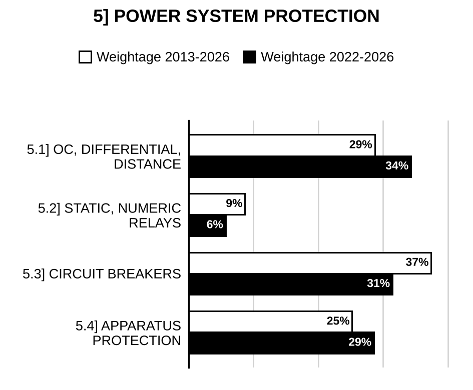
5.1] Overcurrent, differential and distance protection
29 questions
In a percentage differential protection scheme, the current in the secondary of the current transformer at one end is 3.4 Amp and the current in the secondary of the current transformer at the other end is 3.0 Amp. The number of turns of the operating coil is 400. Determine the number of turns of the restraining coil for the balance condition. Also explain the requirement of biasing. [2026/10m/5c]
With the help of circuit diagram and phasor diagram, explain the working of a Translay relay. [2026/10m/7c]
What is the universal relay torque equation? Using this equation, derive the impedance relay, reactance relay and mho relay characteristics. Also draw the operating characteristic and indicate clearly the zones of operation and no operation. [2023/20m/7b]
Answer the following: (i) Write the recommended expression for time-current relationship of standard IDMT relay and draw its characteristic curve. Why is this type of relay commonly used for protection of electrical machines? (ii) Draw the circuit arrangements for connecting earth fault relay in 3ϕ supply and explain its working for core balance current transformer as well as for three CT system. [2022/20m/8a]
Discuss the percentage differential Relay with harmonic restraint with the help of diagram and also draw the conceptual representation of it. [2021/20m/7a]
Explain the principle of percentage biased differential relay with harmonic restraint. [2017/10m/1e]
Obtain three zone settings for (i) a reactance relay and (ii) a mho relay of 60° from the following data: CT: 400/1 A PT: 132 kV/110 V Impedance for the first section is ohms (primary) and that of second section is ohms (primary). The first zone covers 80% of the first section, the second zone covers the first section plus 30% of the second section and the third zone covers the first section plus 120% of the second section. [2015/20m/6b]
Draw the typical characteristics of an IDMT Relay and explain how to use these curves. [2014/10m/1d]
An IDMT Relay has a current setting of 150% and has a time multiple setting of 0.5. The relay is connected in a circuit through a C.T. having a ratio of 500 : 5 amps. Calculate the time of operation of the relay if the circuit carries a fault current of 6,000 A. Use the table given below:
| P.S.M. | 2 | 3.6 | 5 | 8 | 10 | 15 | 20 |
| Time in seconds for T.M.S. of 1.0 | 10 | 6 | 3.9 | 3.15 | 2.8 | 2.2 | 2.1 |
[2014/10m/2c]
Show how unit protection principle can be employed in balanced voltage system. [2014/10m/8c]
Define the terms given below: (i) Pick up value (ii) Reset time (iii) Operating time and (iv) Reset value for protective relays. [2013/10m/1d]
Time-current characteristic of an induction-type overcurrent relay is: It is desired to determine the time of operation of 5-ampere relay having a current setting of 125% and TMS of 0.6 connected to a supply circuit through a C.T. ratio 400/5 ampere when the circuit carries a fault current of 4,000 amperes.
| I (Multiples of pick-up) | 2 | 4 | 6 | 8 | 10 | 12 | 14 | 16 | 20 |
| T (Seconds) | 10 | 5.1 | 4 | 3.4 | 3 | 2.8 | 2.6 | 2.5 | 2.4 |
[2013/20m/2b]
What is the need for a multi input comparator? Show with diagrams how to obtain the quadrilateral characteristic in the R—X plane using 4-input phase comparator. [2013/10m/5b]
Describe the essential features of protective relay. [2012/10m/1e]
State and briefly explain the basic requirements (i.e., essential qualities) of protective relaying. [2011/20m/2b]
The figure below shows the single-line diagram of a part of a power system. It is provided with distance relays at and . , , and are circuit breakers. The impedances of the sections of the line are shown in ohms:
[Figure: Single-line diagram: source bus A → circuit breaker → line section of 30 Ω (current = 500 A flowing from A towards the junction) → junction J. Source bus B → circuit breaker → line section of 15 Ω (current = 200 A flowing from B towards J) → J. From J a 75 Ω section to the point (fault to ground shown at ), then circuit breaker and, across an intermediate bus, circuit breaker , followed by a further 75 Ω section to the point (fault to ground shown at )]
(i) A fault occurs at as shown in the figure. Calculate the impedance seen by the relay installed at . Will this relay operate before the circuit breaker at has tripped? [2011/5m/8c(i)]
(ii) Will the relay at trip for a fault at before the circuit breaker at has tripped? [2011/5m/8c(ii)]
(iii) If the circuit breaker fails for a fault at , will the fault be cleared by the relays at and ? [2011/5m/8c(iii)]
(iv) How will the fault at be cleared? [2011/5m/8c(iv)]
A certain ring feeder has 6 sections. It is fed at one point only. Using non directional and directional overcurrent relays with suitable line lag, explain the method of protecting this feeder. Assume a minimum operating time of 60 ms for the relays. In the diagram to be drawn, the location of all the relays and whether they are directional or non directional are to be shown. Also the time of operation of all the relays is to be shown by the side of the relay. [2010/20m/3c]
A transmission line is protected by a three zone plain Impedance. Draw the characteristics of this relay in the – diagram. If this relay is provided with a directional feature, what modification is to be made in the characteristics drawn on the – diagram. Also draw the contact diagram of the arrangement assuming directional feature. [2010/10m/5b(ii)]
(i) Draw the Mho and Offset Mho characteristics of a distance relay for the protection of transmission lines and give the main applications of offset Mho relay. (ii) A 3 phase, 2 pole, 11 kV, 10,000 kVA alternator has neutral earthed through a resistance of 7 ohms. The machine has current balance protection which operates upon out of balance current that exceed 20% of full load. Determine % of winding protected against earth fault. Exclude the % reactance of generator winding for calculation. [2009/20m/3c]
(i) Give two reasons for using c.t.s. for over-current protection in ac medium voltage distribution and subtransmission of power systems. Explain the term ‘Plug Setting’ (P.S.), define ‘Plug Setting Multiplier’ (P.S.M.) and draw a typical time of operation t (in seconds) versus P.S.M. characteristic of an Inverse Definite Minimum Time Lag (IDMTL) overcurrent relay showing its speciality. (ii) Draw the c.t.s., phase and ground fault overcurrent relay connection diagram at a substation for the minimum number of relays to cater for all types of fault on a 3-phase overhead line. What modification is necessary to extract information about the type of fault? (iii) For a radial 3 phase 11 kV, 50 Hz line ABCD fed at A only, a relay at substation C clears the 3-phase 200 MVA fault close to C in section CD of very short length in 0.1 sec. Find the P.S., P.S.M. and the Time Setting Multiplier (T.S.M.) of the IDMTL overcurrent relay at substation B connected via 400/5 amp c.t.s. to provide a discrimination time of 0.5 seconds. The nomograph of the relay for TSM = 1.0 is as follows:
| t (in secs) | 31.6 | 3 | 2.4 | 2.2 |
| P.S.M. | 1.3 | 10 | 16 | 20 |
Justify the discrimination time of 0.5 seconds based on a 5 cycle breaker. For choosing P.S., P.S.M. should be as close to 20 as possible. [2009/20m/5b]
(i) Show how three distance relays should be connected to current and potential transformers of a 3-phase transmission line in order that the protective system has the same sensitivity for all types of multiphase faults. What will be the response of this protective system to single-phase earth faults? (ii) What is the effect of fault impedance on the performance of distance protection? Suggest a method for overcoming this effect. [2006/20m/3c]
The time-current characteristic of an induction-type over current relay is.
| I (multiples of pick up) | T (Seconds) |
| 2 | 14 |
| 4 | 6 |
| 6 | 4.8 |
| 8 | 4.1 |
| 10 | 3.5 |
| 12 | 3 |
| 16 | 2.6 |
| 20 | 2.5 |
| 30 | 2.4 |
It is desired to determine the time of operation of a 5- ampere relay having a current setting of 125 per cent and give time-multiplier setting of 06 connected to a supply circuit through a C.T. ratio of 400/5 amperes when the circuit carries a fault current of 4000 amperes. [2005/20m/3c]
State and explain the basic requirements (i.e. essential qualities) of protective relaying. [2004/20m/3c]
Discuss the basic principles involved in distance protection and describe how it is applied to transformer feeders. [2001/20m/8c]
Which type of distance relay is preferred for EHV transmission lines? Discuss its principle of operation with its salient features. [1999/20m/6a]
Select any three of the following statements and justify the correctness or otherwise of them, restricting your answer to within 200 words for each. Impedance relays used for transmission line protection work in conjunction with directional relays. [1998/20m/200w/5b]
Explain the need for time-grading in the protective scheme for radial feeders. Explain how the multiplier setting, plug-setting affect the time of operation of the relay. [1998/20m/6c]
Explain the working principle of a time graded protective scheme for radial feeders. Explain further with a sketch of a ring main feeder, why the time graded protective scheme has to be supplemented by directional control. [1997/20m/8b]
An 11 kV, 3-phase radial feeder is equipped with two current transformers along with their associated I.D.M.T.L. relays at two different locations. The c.t. ratios are 600/5 and 200/5 respectively and the relay associated with each c.t. has the following characteristic,.
| Plug Setting Multiplier (PSM) | Times in secs |
| 2 | 10 |
| 3 | 6 |
| 5 | 4.1 |
| 10 | 3.0 |
| 15 | 2.5 |
| 20 | 2.2 |
The relay on 200/5 c.t. has a 150% plug setting and 0.2 time multiplier setting. Determine the time of operation of this relay, if the fault current through the feeder is 3000amps. Also calculate the time setting and time of operation of the other relay connected to 600/5 c.t. assuming a plug setting of 200% and taking into consideration the adequate discrimination margin of 0.5 sec. [1997/20m/8c]
5.2] Relays
11 questions
With the help of schematic and circuit diagrams, describe the operation of a static differential protection relay, using the rectifier bridge amplitude comparator. [2025/10m/7c]
Describe the principle of numerical protection. How is this method of protection different from conventional methods? [2016/10m/2c]
Explain the advantages of numerical relays. [2015/10m/5c]
Draw the block diagram and explain various components involved in digital signal processing for a numerical relay. [2015/10m/7c]
Draw the block diagram of a Digital Relay and name all the blocks of this relay. [2013/10m/8c]
.
(i) What are the basic elements of a static relay? Describe the function of each element. [2012/12m/6a(i)]
(ii) What are the advantages of static overcurrent relays over the electromagnetic form? [2012/8m/6a(ii)]
(i) Why do you need the harmonic restraint in the application of differential protection to power transformers? With the help of relevant circuit diagram, explain how this harmonic restraint scheme operates? (ii) “Relays are comparators”. Justify this statement. Show that an inherent two input amplitude comparator can work as a phase comparator and vice-versa. [2010/20m/8c]
Draw the block diagram of a microprocessor based distance relay for protection of transmission line. [2009/20m/8c]
Draw a schematic block diagram of a microprocessor based system for over-current protection. Describe the operation of the system. With the help of a flow chart or otherwise explain associated system software. [2006/20m/8a]
Describe microprocessor – based inverse – time over current (ITOC) relay with a neat schematic block diagram. [2005/20m/8c]
Describe the construction and principle of working of a solid-state and over-current relay. [2000/20m/2c]

Preparing for Prelims too?
Our UPSC Prelims Topic-wise PYQ eBook covers every Prelims question with detailed explanations, so you can see exactly where UPSC asks from.
View the BookDownload Free Sample5.3] Circuit breakers
33 questions
A 3-cycle circuit breaker is connected between a generator and transformer of 20 MVA, 11 kV rating with reactances , and . The transformer is operating at no load and rated voltage. Determine the interrupting current and interrupting kVA by the circuit breaker when a 3-phase fault occurs between the circuit breaker and the transformer. [2026/10m/6c]
An 11 kV, 50 Hz alternator is connected to a system which has inductance and capacitance per phase of 10 mH and 0.01 μF respectively. Determine (i) the maximum voltage across circuit breaker contacts, (ii) the frequency of transient oscillation, (iii) the average RRRV and (iv) the maximum RRRV. [2025/10m/5c]
Calculate the peak voltage which appears across the terminals of a circuit breaker when it suddenly interrupts 20 A current at 20% of its peak value in a circuit. The inductance and stray capacitance of circuit are 15 H and 3000 pF respectively. [2024/10m/8c]
A circuit breaker is rated as 2500 A, 1500 MVA, 33 kV, 3 sec, 3-phase, oil circuit breaker. Determine its rated normal current, breaking current, making current and short-time rating (current). [2023/10m/1b]
Explain how arc is initiated and sustained in a circuit breaker when the circuit breaker contact separates. Also, derive an expression for the restriking voltage in terms of system voltage, inductance and capacitance, across the circuit breaker contacts. (Assume that the neutral of the system is solidly grounded) [2022/10m/5c]
A 50 Hz, 11 kV, three-phase synchronous generator with earthed neutral has a reactance of 4 Ω/phase and is connected to a busbar through a circuit breaker (CB). The capacitance to earth for the CB and generator is 0.02 μF per phase, and resistance may be ignored. Find the maximum voltage across the contacts of the circuit breaker, frequency of the transient oscillation and the average rate of rise of restriking voltage up to the first peak of the oscillation. [2022/10m/6b(ii)]
(i) What is Buchholz relay? Which equipment is protected by it? Discuss its working principle. (ii) A circuit breaker interrupts the magnetizing current of a 100 MVA transformer at 220 kV. The magnetizing current of the transformer is 5% of the full-load current. Determine the maximum voltage which may appear across the gap of the breaker when the magnetizing current is interrupted at 53% of its peak value. The stray capacitance is 2500 μF and the inductance is 30 H. [2020/20m/4a]
In a 220 kV system, the reactance and capacitance up to the location of circuit breaker is 8 Ω and 0.025 μF, respectively. A resistance of 600 Ω is connected across the contacts of the circuit breaker. Determine the following: (i) Natural frequency of oscillation (ii) Frequency of damped oscillation (iii) Critical value of resistance which will give no transient oscillation (iv) The value of resistance which will give frequency of damped oscillation, one-fourth of the natural frequency of oscillation. [2020/10m/5d]
For a 3-ϕ, 50 Hz, 132 kV system, the reactance and capacitance up to the location of the circuit breaker are 3 Ω and 0.015 μF respectively. Calculate the following: (i) The frequency of transient oscillation (ii) The maximum value of restriking voltage across the contacts of the circuit breaker (iii) The maximum value of rate of rise of restriking voltage (RRRV) [2019/10m/5a]
Write about the selection of various circuit breakers for different ranges of system voltage. Mention the type of circuit breaker to be recommended by the utilities for a particular range of voltage. [2018/10m/6a(i)]
Discuss the difficulty in the development of high voltage DC (HVDC) circuit breaker. Describe its construction and principle of operation. [2018/10m/6a(ii)]
What are the different methods of testing of circuit breakers? Discuss their merits and demerits. Which method is more suitable for testing the circuit breakers of large capacity? [2016/20m/3c]
A circuit breaker interrupts the magnetising current of a 100 MVA transformer at 220 kV. The magnetising current of the transformer is 5% of the full load current. Determine the maximum voltage which may appear across the gap of the breaker when the magnetising current is interrupted at 53% of its peak value. The stray capacitance is 2500 μF and the inductance is 30 H. [2016/10m/5d]
Discuss the operating principle of circuit breaker. What are its advantages over other types of circuit breakers? In practice, for what voltage range is it recommended? [2016/20m/8b]
What are the advantages and limitations of air-blast circuit breaker? [2015/10m/8b(i)]
It is required to install a circuit breaker for a 3-phase, 50 Hz, 220 kV, 500 MVA substation. Select the suitable circuit breaker along its specifications. [2015/10m/8b(ii)]
In a 220 kV, 50 c/s power system, the reactance and capacitance upto the circuit breaker are 8 ohms and 0.025 μF respectively. A resistance of 600 ohms is connected across the circuit breaker contacts. Determine the following: (i) Natural frequency of oscillation (ii) Damped frequency of oscillation (iii) Value of Critical Resistance which will give no transient oscillations (iv) The value of resistance which when connected across circuit breaker contacts will give damped frequency of oscillation of one-fourth of the natural frequency of oscillation. [2014/20m/8b]
An 11-kV, 50-Hz generator was supplying power to a load when a three-phase fault occurred on the system. The inductive reactance and capacitance of the faulted section were 4.0 ohms and 0.01 μF respectively, and the resistance was negligible. Compute (a) the active recovery voltage, (b) peak value of the restriking voltage, (c) the frequency of transient oscillatory voltage and (d) the average rate-of-rise of restriking voltage (RRRV) up to the first peak of oscillations. [2013/20m/3c]
What is circuit breaker rating? Explain the rated making capacity of a circuit breaker. [2012/10m/5e]
What is the importance of testing of a circuit breaker? Explain different tests carried out to prove the ability of a circuit breaker. [2012/20m/8a]
Discuss in brief the physical, chemical and electrical properties of gas with respect to its application in high-voltage circuit breakers. [2011/20m/3c]
(i) Differentiate between “Restriking Phenomenon” and “Reclosing Phenomenon” in a circuit breaker. Which one is harmful and which one is useful and why? (ii) A simple power system is shown operating on NO LOAD.
[Figure: a.c. source (generator) connected through a series inductance L to a node; capacitance C from that node to the return line; from the same node a circuit breaker (box marked “CB closed”) leads to the output terminals, which are marked “open circuit” (no load connected)]
A fault occurs at the far end of the system and the breaker contacts separate. Derive an expression for the voltage across the breaker contacts. Find the frequency of oscillation of the recovery voltage. What is the highest value of the Restriking Voltage and when does it occur. [2010/20m/2b]
What is “resistance switching” as applied to circuit breaker operation? Why is it resorted to? Derive an expression for the value of the resistance to be used in terms of system parameters. [2010/10m/5b(i)]
(i) List the merits and demerits of outdoor circuit breakers. (ii) Draw a simple one line diagram of a generator breaker using breaker connecting the generator to EHV bus through a main transformer. [2009/20m/2b]
Explain why it is more difficult to interrupt short-circuit current in an HVDC circuit than that in an HVAC circuit. [2007/20m/5c]
In a 132-kV, 3-phase earthed-neutral transmission circuit, a 3-phase solid fault occurred at some distance from the circuit breaker in substation. The power factor of the faulted section of the circuit (between the breaker and the fault) was 0.3, the recovery voltage was 0.95 of the full rated value, the breaking current was symmetrical and the restriking voltage transient had a natural frequency of 16 kHz. Compute the average value of the rate-of-rise of restriking voltage (RRRV). [2006/20m/8c]
Select any THREE of the following statements, read them carefully and identify the correct and the incorrect ones. Justify your answer using not more than 200 words in each case:- An HVAC circuit breaker of a given voltage, current and MVA rating can be used as an HVDC circuit breaker of the same voltage, current and MVA rating. [2004/20m/200w/5c]
Select any three of the following statements, read them carefully and identify the correct and the incorrect ones. Justify your answer using not more than 200 words in each case The chances of arc interruption in subsequent current zero increase in case of air blast C.B. but decrease in oil C.B. [2003/20m/200w/5c]
Select any three of the following statements, read them carefully and identify the correct and the incorrect ones. Justify your answer using not more than 200 words in each case For the same rupturing capacity the actual current to be interrupted by an HRC fuse is much greater than that of any circuit breaker. [2002/20m/200w/5c]
Select any three of the following statements and justify the correctness or otherwise of them, restricting your answer to within 200 words for each: Restriking transients can be damped by connecting a resistance across the contracts of a circuit breaker. [1999/20m/200w/5a]
Select any three of the following statements and justify the correctness or otherwise of them, restricting your answer to within 200 words for each. An axial blast circuit breaker is not prone to current chopping. [1998/20m/200w/5d]
Distinguish between Restriking voltage and Recovery voltage as applied in case of a circuit breaker. On what factors the Active Recovery voltage depends? What is the maximum value of the peak Restriking voltage transient? [1997/20m/6a]
With a neat sketch explain the working principle of an Axial blast circuit breaker. Explain why such a circuit breaker is prone to current chopping. What is the voltage expected across the contacts of the circuit breaker under such a condition? [1997/20m/6b]
5.4] Apparatus protection
29 questions
Write the abnormal running conditions of a generator and discuss the protection scheme against them. [2026/10m/8c]
A 3-phase, 33 kV, star-connected alternator is to be protected using circulating current protection. The pilot wires are connected to the secondary windings of 100/5 ratio current transformer. The protective relay is adjusted to operate with an out of balance current of 1 A in the pilot wires. Determine (i) the earthing resistance which will protect 90% of the winding and (ii) the percent of the winding which would be protected, if the earthing resistance is . [2025/10m/6c]
Calculate the current setting of a relay for fault that draws up to 400% of the rated current. The relay is used for differential protection of a delta-star, 50 MVA, 66/11 kV transformer. The CT ratio on secondary side is and primary side is . [2024/20m/8b]
Consider a three-phase, Δ-Y connected, 30 MVA, 33/11 kV transformer with differential relay protection. If the CT ratios are on the primary side and on the secondary side, compute the relay current setting for faults drawing up to 200% of rated transformer current. [2023/10m/5e]
A solidly earthed 400 KV, 3 phase busbar system is connected with two incoming and four outgoing lines (feeders). A differential protection is provided with switchgear of 4000 MVA capacity having the following parameters:
| CT secondary resistance | = 0.8 Ω |
| Lead wire resistance | = 1.2 Ω |
| Relay load | = 1.0 Ω |
| CT magnetization current | = 0.3 mA/V |
| Max. full load current in one feeder | = 100 A |
| Voltage setting of over current relay | = 100 V |
If the O.C. relay in the spill path is set at 1.0 A, find the following: (a) The maximum ‘through fault’ current up to which the protection scheme remains stable. (b) Whether the switchgear is capable to handle maximum through fault current. (c) The value of minimum internal fault current that can be detected by protection scheme. (d) The pick-up setting for detecting minimum internal fault current of 90 Amp. [2021/20m/3a]
Discuss the percentage differential Relay with harmonic restraint with the help of diagram and also draw the conceptual representation of it. [2021/20m/7a]
(i) What is Buchholz relay? Which equipment is protected by it? Discuss its working principle. (ii) A circuit breaker interrupts the magnetizing current of a 100 MVA transformer at 220 kV. The magnetizing current of the transformer is 5% of the full-load current. Determine the maximum voltage which may appear across the gap of the breaker when the magnetizing current is interrupted at 53% of its peak value. The stray capacitance is 2500 μF and the inductance is 30 H. [2020/20m/4a]
The figure given below shows percentage differential relay applied to the protection of an alternator winding. The relay has 0.1 ampere minimum pick-up and 10% slope of characteristic vs . A high-resistance ground fault occurred near the grounded neutral end of generator winding, while the generator is carrying load. As a consequence, the currents in ampere flowing at each end of the winding are shown in the figure. Assume CT ratio of 400/5. Will the relay operate to trip the breaker?
[Figure: Generator Winding (with a ground connection shown at its middle) with a 400/5 CT at each end; current 320+j0 A flows into the winding at the right-hand end and 304+j0 A flows out at the left-hand end (both arrows pointing left); the CT secondaries are connected by pilot wires through the restraining coil R of the relay, and the operating coil O of the relay is connected between the mid-point of the restraining coil and the other pilot wire (relay shown in a dashed box)] [2019/20m/4b]
An 11 kV, 100 MVA alternator is provided with differential protection. The percentage of winding to be protected against phase-to-ground fault is 85%. The relay is set to operate when there is 20% out of balance current. Determine the value of the resistance to be placed in the neutral-to-ground connection. [2018/10m/3c]
Explain the principle of percentage biased differential relay with harmonic restraint. [2017/10m/1e]
Explain what is meant by Bewley-Lattice diagram. What is the use of this diagram? [2014/10m/3c]
Explain the importance of adding impedance in the neutral path of an alternator. [2014/10m/5d]
A three-phase, 66 kV/11 kV transformer is connected in star/delta. The transformer is protected by Merz-Price circulating current system. Protecting current transformers on the low-voltage side have a ratio of 250/5. Find the ratio of the current transformer on the high-voltage side. [2012/20m/2b]
.
(i) Show the schematic diagram of a power line carrier protection scheme for a transmission line. [2011/8m/5b(i)]
(ii) Which are the components you consider most vital in the scheme? [2011/4m/5b(ii)]
(iii) Using the principle of phase comparison, explain how the scheme works. [2011/8m/5b(iii)]
(i) Why do you need the harmonic restraint in the application of differential protection to power transformers? With the help of relevant circuit diagram, explain how this harmonic restraint scheme operates? (ii) “Relays are comparators”. Justify this statement. Show that an inherent two input amplitude comparator can work as a phase comparator and vice-versa. [2010/20m/8c]
(i) Draw the Mho and Offset Mho characteristics of a distance relay for the protection of transmission lines and give the main applications of offset Mho relay. (ii) A 3 phase, 2 pole, 11 kV, 10,000 kVA alternator has neutral earthed through a resistance of 7 ohms. The machine has current balance protection which operates upon out of balance current that exceed 20% of full load. Determine % of winding protected against earth fault. Exclude the % reactance of generator winding for calculation. [2009/20m/3c]
(i) A power transformer is connected in ⅄/Δ fashion. Draw the arrangement of the current transformers (CTs) on either side of the transformer for Merz-Price circulating current protection. (ii) A distribution transformer is to be protected by over- current relays against all kinds of fault. List the different kinds of fault and suggest the minimum number of over-current relays required. How would those over-current relays be placed in the circuit? (iii) How would one protect a direct-on-line (DOL) start induction motor against overload? Explain your choice. [2007/20m/3c]
Explain on-line real-time computer system for protection of a line. Draw a sample fault program flow diagram. [2004/20m/8c]
Explain with reasons the connection of C.T.s for protecting a delta/star transformer Justify your scheme of protection for (i) internal fault and (ii) external fault, using Merz-Price protection. [2003/20m/3b]
Explain briefly various abnormal operating conditions in a large alternator against which protection is necessary. Explain clearly with neat diagram the protection of alternator against failure of excitation. [2002/20m/3b]
Explain how a Buchholz relay protects a transformer. [2001/20m/2c]
Explain the following in connection with power systems: Ferranti effects, infinite line, Peterson coil, load bus. [2001/20m/3b]
An overhead transmission line, with a surge impedance of 500 Ω, has a load comprising of a 10 kilo-ohm resistor is parallel with a 0.005 μF capacitor connected across the far end. A surge voltage of 10 kV magnitude and unit step travels along the line. Determine an expression for the time variation of the voltage across the load and calculate this voltage 5 μs after the arrival of the wave front of the surge. State any assumptions made. [1999/20m/7a]
What are the factors affecting corona power loss in a transmission line? An inductance L connects two sections of a transmission line with surge impedances , and . A rectangular surge with a crest value “V” and of “t” microseconds travels along the line-section 1 towards the inductance. What is the maximum value of the transmitted wave? [1998/20m/6b]
What are the most important requirements of a lightning arrester? A thyrite lightning arrester has a characteristic . Draw the Volt-ampere characteristic of the arrester. What is the ratio of the voltage appearing at the end of a line with a surge impedance of 500 ohms, due to a 500 kV surge when the line is open circuited to that when the line is terminated by the arrester? [1998/20m/7a]
Ground wires protect transmission lines against direct lightning strokes. [1997/20m/200w/5b]
An 11 kV, 1-MVA, Y-connected generator has a reactance of 4.2 ohms/phase. The generator neutral is grounded through a resistance of 22 ohms. Determine what percent of the generator winding remains unprotected by the percentage differential relaying. Assume for simplicity that the percentage differential relay operates when out-of-balance current exceeds 25% of the full-load current. [1996/20m/8c]
Lightning arrestor should be located as close to the transformer being protected as is physically possible. [1995/20m/200w/5a]
A 40 MVA, 3-phase, 345/34.5 kV transformer is star/delta connected. Select standard CT ratios on the two sides of the transformer for percentage differential protection of the transformer. Would an auto-transformer be required? If so, what should be its current ratio? [1995/30m/8c]

Strengthen your GS papers
Our UPSC Mains Topic-wise & Year-wise PYQ eBook (2013–2026) maps every GS question to the syllabus, so you know what UPSC asks and how often.
View the BookDownload Free Sample« Previous: Power Systems: Analysis and Control | Next: Digital Communication »
Back to: Electrical Engineering Optional PYQs – Topic-wise
Last updated: 30 October 2026