
Here are all 172 Power Systems: Analysis and Control questions asked in UPSC Electrical Engineering Optional Paper II from 1995 to 2026, arranged under the 8 topics of the official syllabus. Within each topic the latest questions come first.
Each question ends with a code such as [2024/15m/3b] – the year, the marks, the word limit (where UPSC set one) and the question number in the paper.
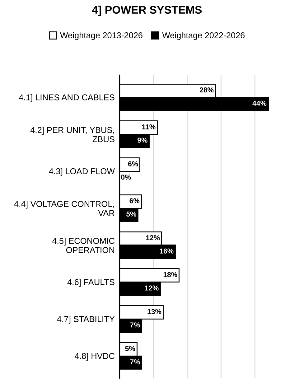
4.1] Transmission lines and cables
39 questions
Determine the efficiency of a 400 km long transmission line delivering 100 MW load at 240 kV, 0.85 lagging p.f. at the receiving end. The series impedance and shunt admittance per kilometre are ohm and mho respectively. [2026/20m/6a]
A 3-phase line is terminated by a star-connected resistive load of 800 ohm per phase. The line conductors are equilaterally spaced 2.0 m apart and have a diameter of 2 cm. The voltage wave travelling along the line is of 33 kV. Determine the power reflected by the load and the power consumed by the line. [2026/20m/7a]
A hollow cylinder made of insulating material surrounded by a thin metal sheath has inner and outer diameters of 4 cm and 8 cm respectively. The relative permittivity of the cylinder material is 4 and peak voltage gradient in air is 33 kV/cm. Determine the rms value of safe operating voltage of a conductor passing through the centre of the cylinder and having a diameter of 2 cm. [2026/20m/8a]
Determine the sending-end voltage, current, power factor of a single-phase, 50 Hz, 76.2 kV transmission line delivering a load of 12 MW at 0.8 p.f. lagging. The line constants are , inductance 200 mH and capacitance between lines is . Also determine the regulation and efficiency of the transmission. Use nominal- method. Draw the phasor diagram. [2025/20m/6a]
The capacitances of a 3-core cable of belted type are measured and found to be as follows: (i) Between 3 cores bunched together and the sheath, 8 μF (ii) Between one conductor and the other two connected together to the sheath, 5 μF Calculate the capacitance to the neutral and the total charging kVA, when the cable is connected to an 11 kV, 50 Hz, 3-phase supply. [2025/10m/8c]
Calculate the power loss in a cable insulation having capacitance 9 μF, loss angle 0.05 degree and operating at 11 kV, 50 Hz. Draw the phasor diagram and equivalent circuit also. [2024/10m/1d]
A single core cable without grading operates at 14 kV. The conductor radius is 1.12 cm and insulation radius is 2.75 cm. If cable is with inter-sheath grading at suitable radius, then calculate the maximum operating voltage of the cable. [2024/10m/5d]
Calculate the real and reactive power at sending end of a transmission line while delivering 10 MVA load at 0.85 lagging power factor at receiving end of line. The line parameters are A = 1, , D = 1 and receiving end voltage of line is 33 kV. [2024/20m/7a]
In a three-phase 400 km long transmission line, the conductors are spaced at the corners of an equilateral triangle of side 5 m. The diameter of each conductor is 3 cm. Calculate the capacitance per phase of the 400 km long conductor. [2023/10m/1e]
A 6600 V, 50 Hz, single-core, lead-sheathed cable has the following data: Conductor diameter = 1.6 cm Length = 5 km Internal diameter of the sheath = 3.2 cm Resistivity of insulation = Relative permittivity of insulation = 3.8 Calculate the insulation resistance, capacitance and the maximum electric stress in the insulation. [2023/10m/3c]
A transmission line has the following parameters: (i) Determine the sending-end voltage and the voltage regulation if the line supplies a load of 40 MW at 0.8 p.f. lagging with receiving-end voltage 132 kV. (ii) Find the power and power factor of the load if the voltages at the two ends are 132 kV and with a phase difference of 30°. [2023/20m/4b]
Determine the inductance of a single-phase transmission line consisting of three conductors of 2 cm radii in the ‘go’ conductor and two conductors of 4 cm radii in the ‘return’ conductor as shown in the figure below:
[Figure: Composite conductor A (left): conductors a, b, c in a vertical line, a–b = 4 m, b–c = 4 m. Composite conductor B (right): conductors a′ and b′ in a vertical line 4 m apart, a′ level with a and b′ level with b; horizontal distance between the two columns (a to a′) 6 m.] [2022/10m/5a]
A three-phase, 50 Hz transmission line is 400 km long. The voltage at the sending end is 220 kV. The line parameters are , and . (i) Find the sending-end current and receiving-end voltage when there is no load on the line. Comment on the result. (ii) Find the maximum permissible line length if the receiving-end no-load voltage is not to exceed 230 kV. (iii) Find the maximum permissible line frequency if the no-load voltage is not to exceed 250 kV. [2022/20m/6a]
The configuration of a 400 KV 3 phase line is shown in figure. The radius of each sub-conductor is 2 cm. Calculate the charging mega volt-amperes if line is operating at 50 Hz and has a length of 300 km.
[Figure: Horizontal configuration of three bundled phases, each of two sub-conductors: a and a′, b and b′, c and c′; the two sub-conductors of each phase are 0.5 m apart. The distance between the centres of adjacent phase bundles (a–b and b–c) is 10 m.] [2021/10m/4a(i)]
Calculate the most economical overall diameter of insulation of a cable to be operated at 400 KV, 3 phase power system if maximum stress is limited to 100 KV/cm. [2021/10m/4a(ii)]
(i) What are the advantages of per unit representation? (ii) Using the nominal π method, find the sending-end voltage and voltage regulation of a 250 km, 3-phase, 50 Hz transmission line delivering 25 MVA at 0.8 lagging power factor to a balanced load at 132 kV. The line conductors are spaced equilaterally 3 m apart. The conductor resistance is 0.11 Ω/km and its effective diameter is 1.6 cm. Neglect leakance. [2020/20m/6b]
What is grading of cables? What are the different methods of grading? What are its limitations? [2020/10m/8c]
An 11 kV single-core cable has a conductor radius of 8.8 mm and an insulation thickness of 4.6 mm. Find the maximum and minimum electric stress. [2019/10m/1b]
A 3-phase, 11 kV transmission line delivers a load of 2395 kVA at 0.8 p.f. (lag) over a distance of 25 km. The transmission line has an impedance per phase of ohms. Determine the sending-end voltage and sending-end power factor. [2018/20m/2a]
Determine the equivalent constants of Network–1 connected in tandem with Network–2 as shown in the figure given below:
[Figure: Two two-port networks in tandem (each in a dashed box). Network–1 (): a series impedance in the top line; input voltage and input current at the left; output current and voltage at the junction. Network–2 (): a shunt impedance across the line; output voltage and output current at the right] [2015/10m/7a(i)]
A transmission line has its electrical length of 5 electrical degrees. Find its physical length. The frequency of supply is 50 Hz. Express the physical length in terms of wavelength of the line. [2015/10m/7a(ii)]
(i) Draw the equivalent of a medium length transmission line using -model. (ii) Assume that the receiving end is supplying a lagging power factor load. Draw the Phasor diagram showing all voltages and currents. (iii) Derive the A, B, C and D constants of this line in terms of line parameters Z and Y. [2014/20m/3b]
A 3-phase 138-kV, transmission line is connected to a 49-MW load at a 0.85 lagging power factor. The line constants of the 80 km long line are and S. Using nominal-T circuit representation, compute: (i) The A, B, C and D constants of the line; (ii) Sending-end voltage; (iii) Sending-end current; (iv) Sending-end power factor; and (v) Efficiency of transmission. [2013/10m/1b]
State various insulating materials used for cables and comparatively discuss any two widely used materials. [2013/10m/5d]
.
(i) What is the impedance of the ideal load connected to an HVAC transmission line? [2012/2m/1d(i)]
(ii) What is the nature of the load of an HVAC transmission line by itself, capacitive or inductive? [2012/2m/1d(ii)]
(iii) Which electrical quantity measures the magnitude of electrical load in a system? What is generally the nature of the load current, capacitive or inductive, in the power system? [2012/2m/1d(iii)]
(iv) Under which condition is the receiving-end voltage higher than the sending-end voltage in a transmission line? Explain with the help of a phasor diagram. [2012/4m/1d(iv)]
A 110-kV, 50-Hz, 3-phase, 200-km long line has resistance and reactance of 40 ohms and 80 ohms per phase respectively. The capacitance of each conductor to neutral is 1.68 μF. If the receiving-end voltage is 110 kV at no load, compute– (i) the sending-end voltage at no load; (ii) the line charging current; (iii) the kVA supplied to the line; (iv) the open-circuit power loss in the line. Assume a nominal- circuit for the line. [2011/20m/1b]
A 50-Hz, three-phase transmission line is 250 km long. It has a total series impedance of and a shunt admittance of . It delivers 40 MW at 220 kV with 0.9 power factor lagging. Find the voltage at the sending end by the nominal- approximation. [2009/20m/1b]
For overhead transmission lines, shunt admittance is mainly capacitive susceptance ()’. Comment. [2006/20m/1c]
Select any three of the following statements, read them carefully and identify the correct and the incorrect ones. Justify your answer using not more than 200 words in each case. In a long transmission line, the sending-end voltage is always greater than the receiving-end voltage and this effect is known as Ferranti effect. [2005/20m/200w/5c]
Define surge impedance of a line and discuss the advantages and disadvantages of operating an overhead line corresponding to surge impedance loading. Also explain the terms infinite line, flat line. [2003/20m/2b]
Explain the following in connection with power systems: Ferranti effects, infinite line, Peterson coil, load bus. [2001/20m/3b]
Select any THREE of the following statements, read them carefully and identify the correct and the incorrect ones. Justify your answer using not more than 200 words in each case. In order to increase the distance between poles, carrying long distance transmission line, aluminum conductors should be strengthened by strain-hardening. [2001/20m/200w/5a]
The generalized constants A and B of a transmission line are and respectively. If the line to line voltages at the sending and receiving ends are both 110 kV and phase angle between them is 30°, find the receiving end power factor and current. With the sending end voltage maintained at 110 kV, if the load is suddenly thrown off, find the corresponding receiving end voltage. [1999/20m/8c]
What are the factors affecting corona power loss in a transmission line? An inductance L connects two sections of a transmission line with surge impedances , and . A rectangular surge with a crest value “V” and of “t” microseconds travels along the line-section 1 towards the inductance. What is the maximum value of the transmitted wave? [1998/20m/6b]
For EHV transmission lines, it is dangerous to use bundle conductors from the viewpoint of sub-synchronous resonance. [1996/20m/200w/5b]
Derive an expression for the charge (complex) value per meter length of conductor ‘A’ of untransposed 3-phase line shown in Fig. 3. The applied voltage is balanced 3-phase, 50 Hz. Take the voltage of phase ‘A’ as reference phasor. All conductors have the same radii. Also find the charging current of phase A’. Neglect the effect of ground.
[Figure: Fig. 3: Three conductors A, B and C of equal radius in a horizontal row; spacing A–B = p, B–C = q, A–C = r; p = q = D] [1996/20m/6a]
A single-phase, 50 Hz generator supplies an inductive load of 5 MW at a p.f. of 0.707 lagging by means of an overhead line 20 km long. The line R and L are 0.0195 Ω/km and 0.63 mH/km. The voltage at the receiving end is required to be kept constant at 10 kV. Find (i) the sending end voltage regulation of the line, (ii) the value of the capacitors to be placed in parallel with the load such that the regulation is reduced to 50% of that obtained in part (i), (iii) transmission efficiencies in both the cases. [1996/20m/6c]
Explain the concept of self GMD and mutual GMD in respect of 3-phase transmission lines. Indicate how these concepts are used in estimating the inductance and capacitance of 3-phase overhead lines. [1995/15m/6a]
A 3-phase, 50 Hz, transmission line is 400 km long. The voltage at the sending-end is 220 kV. The line parameters are: , , and S/km. Find, using approximate expressions for A, B, C, D constants of long lines, the following: (i) The sending-end current and receiving end voltage when there is no-load on the line. (ii) The minimum permissible line length if the receiving no-load voltage is not to exceed 235 kV. (iii) For part (i), the maximum permissible line frequency, if the no-load voltage is not to exceed 250 kV. [1995/30m/6c]
4.2] Power transfer, per-unit system and network matrices
13 questions
Write the bus admittance matrix for the network shown in the figure.
[Figure: Network with reference bus ⓪ at the top and bus ④ at the bottom. Three branches from bus ⓪, each an element (drawn as an inductor) in parallel with a current source (arrow →): one to bus ②, one to bus ③, one to bus ①. Between buses: ②–③: ; ③–①: ; ②–④: ; ③–④: ; ①–④: (all drawn as inductors).] [2024/10m/5c]
A three-bus network is shown in the figure below, indicating the p.u. impedance of each element:
[Figure: Bus 1 connected to ground through (inductor); bus 1 to bus 2 through (inductor); bus 2 to bus 3 through (capacitor); bus 3 connected to ground through (inductor).]
Find the bus admittance matrix, , of the network. [2023/10m/6a(ii)]
A single-phase distributor ABC fed at A is shown in the figure below. The impedances of the sections AB and BC are same and equal to . The power factors are lagging with respect to the voltage at the far end. If the voltage at the far end is 240 V, then determine the supply voltage and its phase angle with respect to the far end:
[Figure: Distributor A–B–C fed at A (arrow into A); load of 150 A at 0.6 p.f. lagging tapped at B; load of 150 A at 0.8 p.f. lagging at the far end C.] [2023/10m/7c]
The schematic diagram of a radial transmission system is shown in the figure below. The ratings and reactances of various components are shown therein. A load of 60 MW at 0.9 power factor lagging is tapped from 66 kV substation which is to be maintained at 60 kV. Calculate the terminal voltage of the synchronous generator:
[Figure: Single-line diagram: generator at bus – transformer 11/220 kV, 100 MVA, X = 12% – line – transformer 220/66 kV, 100 MVA, X = 10% – bus (marked 60 kV) feeding a load of 60 MW, 0.9 pf lagging.] [2022/10m/5b]
A single phase, single line diagram of a power system is shown in figure. Find the sending end voltage and the value of load resistance in p.u. referred to sending end if the voltage across load resistance is 9.8 KV.
[Figure: Single line diagram: sending end – transformer 11/33 KV, 10 MVA, X = 10% – line (no impedance shown) – transformer 33/10 KV, 10 MVA, X = 12% – receiving end , where an 8 Ω load resistance is connected to ground.] [2021/10m/1b]
(i) What are the advantages of per unit representation? (ii) Using the nominal π method, find the sending-end voltage and voltage regulation of a 250 km, 3-phase, 50 Hz transmission line delivering 25 MVA at 0.8 lagging power factor to a balanced load at 132 kV. The line conductors are spaced equilaterally 3 m apart. The conductor resistance is 0.11 Ω/km and its effective diameter is 1.6 cm. Neglect leakance. [2020/20m/6b]
The primitive impedance matrix of a power system network is given below:
| e \ e | 1 | 2 | 3 | 4 | 5 |
| 1 | 0.6 | 0.1 | 0 | 0.2 | 0 |
| 2 | 0.1 | 0.5 | 0 | 0 | 0 |
| 3 | 0 | 0 | 0.5 | 0 | 0 |
| 4 | 0.2 | 0 | 0 | 0.4 | 0 |
| 5 | 0 | 0 | 0 | 0 | 0.2 |
Find its primitive admittance matrix. [2019/10m/8c]
A generator is connected to an infinite bus as shown in the figure. Derive the expressions for real power and reactive power supplied by the generator to the infinite bus:
[Figure: Generator with internal emf (AC source symbol) connected via a short bus bar (drawn as a vertical line at the generator terminals) through a series reactance (drawn as an inductor) to an infinite bus of voltage ] [2018/10m/1b]
In a system shown in the above figure, two single phase transformers supply a 10 kVA resistance load at 200 V. Show that the p.u. load is the same for each part of the circuit (like part A, B and C) and calculate the voltage at point D.
[Figure: (printed above the question text) Three circuit sections in cascade. Part Ⓐ: AC source with voltage (arrow upwards) connected to the primary of transformer 1 ( V, X = 0.1 p.u., 10 kVA). Part Ⓑ: the secondary of transformer 1 connected by a two-wire circuit, with point D marked on the upper wire, to the primary of transformer 2 ( V, X = 0.15 p.u., 10 kVA). Part Ⓒ: the secondary of transformer 2 supplies a resistance load across which the voltage is 200 V (arrow upwards)] [2017/15m/2c]
For a certain lagging power factor load, the sending end and receiving end voltages of a short transmission line of impedance are equal. Prove that ratio is for maximum power transmitted over the line under steady state condition. [2017/15m/6c]
For a 2-bus system shown below, derive expressions for Real Power and Reactive Power at receiving end and sending end.
[Figure: Single-line diagram: an a.c. generator (~) connected to the sending-end bus, voltage , sending-end power ; a transmission line with constants A, B, C, D connects it to the receiving-end bus, voltage , which feeds a Load (arrow) with .] [2014/20m/2b]
.
(i) Draw power triangles showing the three types of power and their units for– (1) inductive loads; (2) capacitive loads. [2012/10m/3a(i)]
(ii) A single-phase, 240 V a.c. voltage is applied to a series circuit whose impedance is . Find , , and , and also the power factor of the circuit. [2012/10m/3a(ii)]
Develop receiver end power circle diagram of a transmission line. Explain, how from the power circle diagram, capacity of a synchronous phase modifier be determined. [2000/20m/8b]
4.3] Load flow
14 questions
For a 3-bus power system, assume Voltage at bus – 1: pu, Voltage at bus – 2: pu and Voltage at bus – 3: pu. The line impedances are shown below:
| Bus code | Impedances (in p.u.) |
| 1 – 2 | |
| 1 – 3 | |
| 2 – 3 |
Compute Real and Reactive power loss in all the lines and also compute total system loss. [2021/10m/8c]
(i) What informations are obtained from load flow analysis? Explain the necessity of load flow studies. (ii) Explain the advantages of using bus admittance matrix, in load flow analysis. (iii) A power system has two generating plants and the power is being dispatched economically with and . The loss coefficients are To raise the total load on the system by 1 MW will cost an additional ₹ 200 per hour. Find the penalty factor for Plant 1 and the additional cost per hour to increase the output of Plant 1 by 1 MW. [2020/20m/7b]
In the above figure, , pu and pu. Using load flow study iteratively compute and . Also determine the reactive power that must be injected to bus 2 to maintain pu.
[Figure: (printed above the question text) Two-bus system: bus 1 (voltage ) and bus 2 (voltage ) connected by a line of impedance carrying current I from bus 1 towards bus 2 (arrow to the right). Power flows into bus 1 from the left; power flows out of bus 2 to the right] [2017/20m/3a]
Form [B′] and [B″] matrices used in Fast Decoupled Load Flow (FDLF) for the power system shown in Figure 5(b) and line data given in Table I.
[Figure: Figure 5(b): Five-bus single-line diagram: bus ① (generator) at top left; bus ② (generator and load) at bottom left; bus ③ (load) at bottom middle; bus ④ (load) at bottom right; bus ⑤ at top right (arrow pointing upward at bus ⑤). Lines: 1–2, 1–5, 2–3, 3–4, 4–5 and 3–5 (diagonal)]
| Bus Code (i – j) | Impedance () (in p.u.) | Half-line Charging Admittance (in p.u.) |
| 1 – 2 | (0.02 + j 0.04) | j 0.020 |
| 2 – 3 | (0.04 + j 0.20) | j 0.020 |
| 3 – 5 | (0.15 + j 0.40) | j 0.025 |
| 3 – 4 | (0.02 + j 0.06) | j 0.010 |
| 4 – 5 | (0.02 + j 0.04) | j 0.010 |
| 1 – 5 | (0.08 + j 0.20) | j 0.020 |
Table I: Line data [2016/10m/5b]
What is Load Flow solution? What do you understand by (i) Adjustable Load Flow, and (ii) Unadjustable Load Flow? Which method will provide the accurate solution? [2016/10m/8c]
Classify different types of buses for load flow study in power systems. [2013/3m/2c(i)]
Discuss formulation of Newton-Raphson method with mathematical details in polar co-ordinates. [2013/7m/2c(ii)]
Give a brief account of application of computers in the study, analysis and control of power systems. [2007/20m/1c]
For the network shown in Fig. 2 (b), obtain the complex bus bar voltage at bus 2 at the end of the first iteration. Use the Gauss -Seidel method. Line impedances are in pu. Given Bus 1 is slack bus with . ; Assume V and
[Figure: Fig. 2 (b): three buses 1, 2, 3 in a row; line 1–2 impedance 0.04 + j 0.06; line 2–3 impedance 0.02 + j 0.03.] [2001/20m/2b]
What is load flow solution? What is its significance in power system Classify various types of buses in a power system for load flow studies. Explain, with a flow-chart, the computational procedure for load-flow solution using Gauss-Siedel method. [2000/20m/3b]
Select any three of the following statements and justify the correctness or otherwise of them, restricting your answer to within 200 words for each: Gauss-Siedel method is preferred for load flow studies of large power system due to its quadratic convergence. [1999/20m/200w/5b]
Develop necessary equations and explain the Newton-Raphson method in polar co-ordinates for solving the load flow problem when both load and voltage-controlled buses are present in the system. [1999/20m/6b]
Discuss briefly different methods used for Load-Flow studies. Give their merits and demerits. [1996/20m/6b]
Explain clearly with a flowchart, the computational procedure for load flow solution using Gauss-Seidel method when the power system contains all types of buses. [1995/15m/8b]
4.4] Voltage control and reactive power
24 questions
Discuss the saturated-reactor compensator with the help of circuit diagram and V-I characteristics. How can a lower slope of V-I characteristics be obtained? Also write the main features of the saturated-reactor compensator. [2026/10m/1d]
A three-phase, 50 Hz, 415 V supply delivers 250 kW power at power factor of 0.8 lagging. The line power factor is desired to be improved to 0.9 lagging by installing shunt capacitors. Calculate the capacitance if they are connected in delta. [2023/10m/5c]
Explain in brief about the necessity of automatic load frequency control in the power generating system. Draw the schematic diagram of load frequency and voltage control regulators. [2022/10m/7b(i)]
For the system shown in the figure, and are complex power demands at bus-1 and bus-2 respectively. If p.u., compute VAR rating of the capacitor () connected at bus-2 in MVAr:
[Figure: Two-bus system. Bus ① with p.u., fed by generator and supplying load p.u.; bus ① connected to bus ② by a line of reactance p.u.; bus ② supplies load p.u. and has a shunt capacitor connected to ground] [2018/10m/5a]
Two substations are connected by two lines in parallel with negligible impedance, but each containing a tap-changing transformer of reactance 0.18 p.u. on the basis of its rating of 200 MVA. Find the net absorption of reactive power in MVAr when the transformer taps are set to and respectively. Assume per unit voltages to be equal at two ends of the substation. [2018/10m/8c]
Two sub-stations are connected by two lines in parallel with negligible impedance, but each containing a tap-changing transformer of reactance 0.18 p.u. on the basis of its rating of 200 MVA. Find the net absorption of reactive power when the transformer taps are set to 1 : 11 and 1 : 0.9 respectively. Assume p.u. voltages to be equal at the two ends and also at the sub-stations. [2016/10m/1b]
What are the main causes of low power factor and discuss measures by which low power factor can be avoided? [2013/10m/3b(i)]
A consumer is taking a load of 20 kW at power factor 0.8 lagging. Find the rating of capacitor to raise the power factor to 0.95 lagging. [2013/10m/3b(ii)]
.
(i) Define an electrical power grid in one sentence. How is it achieved? [2012/2m/5d(i)]
(ii) Write four main advantages of the electrical power grid system. [2012/2m/5d(ii)]
(iii) What is the purpose of installing a ‘reactor’ at a suitable location on a long high-voltage a.c. transmission line? [2012/2m/5d(iii)]
(iv) Write the full form of FACTS. [2012/2m/5d(iv)]
(v) What are the advantages of ‘reactive power control’ installed on the transmission lines? [2012/2m/5d(v)]
(i) Explain the functions of static systems in transmission. (ii) Discuss different types of static systems () with the aid of neat figures. [2010/20m/1b]
What do you understand by energy conservation? What is the economics of energy conservation? Point out the strategic measures for energy conservation. Show that for a given load current I, if power factor is improved from 0.7 to 0.9, the useful power can be enhanced by 28.6% of the existing system. Comment on the losses due to power factor improvement. [2007/20m/8c]
Select any THREE of the following statements, read them carefully and identify the correct and the incorrect ones. Justify your answer using not more than 200 words in each case:- Is voltage control necessary in power systems? Various current control methods are used. Permissible voltage variations are known. Any advantage of current control? [2004/20m/200w/1c]
Select any THREE of the following statements, read them carefully and identify the correct and the incorrect ones. Justify your answer using not more than 200 words in each case. Tap changing transformers are used in power systems, especially to control reactive volt-amperes. [2001/20m/200w/1c]
Select any three of the following statements, read them carefully and identify the correct and the incorrect ones. Justify your answer using not more than 200 words in each case. Power carrying capability of transmission lines decreases with increase in the length of transmission, and can be improved by providing shunt reactors. [2000/20m/200w/1c]
Develop receiver end power circle diagram of a transmission line. Explain, how from the power circle diagram, capacity of a synchronous phase modifier be determined. [2000/20m/8b]
Show that the use of a synchronous condenser improves the efficiency and regulation of a system. [1999/10m/8c(i)]
A consumer has a total load of 2000 KW at a p.f. of 0.8 lagging. If it is required to improve the power factor to 0.95 lagging, determine the KVA rating of the synchronous condenser required for the purpose. [1999/10m/8c(ii)]
Explain how the power factor of a 3-phase induction motor is controlled by static capacitors. Show that for a constant capacitance, the degree of power factor correction is not the same at different loads. [1999/20m/7c]
Select any three of the following statements and justify the correctness or otherwise of them, restricting your answer to within 200 words for each. The power transfer capability of a transmission system can be enhanced by series-capacitor compensation. [1998/20m/200w/5c]
Explain with the help of a neat phasor diagram, the manner in which a synchronous condenser located at the receiving end of a short transmission line improves the power factor and maintains the voltages at both ends at the same level. [1998/20m/7b]
What is a synchronous condenser? Distinguish between a synchronous condenser and a static var compensator. Why is static var compensation necessary in a power system? [1997/20m/7c]
A 300 kW, 0.65 lagging power factor load is shunted by a capacitor so that the power factor improves to 0.90 lagging. Find the kVAr that the capacitor must furnish and the reduction in apparent power. [1996/20m/2c]
A single-phase, 50 Hz generator supplies an inductive load of 5 MW at a p.f. of 0.707 lagging by means of an overhead line 20 km long. The line R and L are 0.0195 Ω/km and 0.63 mH/km. The voltage at the receiving end is required to be kept constant at 10 kV. Find (i) the sending end voltage regulation of the line, (ii) the value of the capacitors to be placed in parallel with the load such that the regulation is reduced to 50% of that obtained in part (i), (iii) transmission efficiencies in both the cases. [1996/20m/6c]
Tap changing transformers are used in power systems primarily to control reactive volt-amperes. [1995/20m/200w/5b]

Preparing for Prelims too?
Our UPSC Prelims Topic-wise PYQ eBook covers every Prelims question with detailed explanations, so you can see exactly where UPSC asks from.
View the BookDownload Free Sample4.5] Economic operation
22 questions
A factory has a fixed load of 860 kW and is operating at 0.85 power factor. The electric utility company offers to supply energy at the following two alternate rates: (i) LV supply at ₹30/kVA max demand/annum + 12 paise/kWh (ii) HV supply at ₹25/kVA max demand/annum + 10 paise/kWh The HV switchgear costs ₹50/kVA and switchgear losses at full load amount to 4%. Interest and depreciation charges for switchgear are 10% of the capital cost. If the factory is to work 48 hours/week, then determine the more economical tariff option. [2025/10m/1d]
Calculate the power loss in the transmission system given in the following figure. The numerical values of transmission system are: , , , , ,
[Figure: Single-line diagram: generator at Bus 1 (voltage ); line from Bus 1 to Bus 3 carrying (arrow towards Bus 3); generator at Bus 2 (voltage ); line from Bus 2 to Bus 3 carrying (arrow towards Bus 3); Bus 3 (voltage ); line from Bus 3 to Bus 4 carrying (arrow from Bus 3 towards Bus 4); Load supplied from Bus 4.] [2024/20m/6a]
The fuel input equations of two power plant operations are given as: If the maximum and minimum loading on each unit is 90 MW and 20 MW respectively and the total consumption demand is 200 MW, then calculate the economical operating schedule and corresponding cost of generation. If load is equally shared by both units, calculate the savings achieved by loading the units as per equal incremental production cost. Neglect the transmission losses. [2024/20m/6b]
A power system has two generators with the following cost curves: Generator 1: (thousand rupees/hour) Generator 2: (thousand rupees/hour) The generator limits are A load demand of 650 MW is supplied by the generators in an optimal manner. Determine the optimal generation of each generator, neglecting losses in the transmission network. [2023/10m/6a(i)]
Explain in brief about the necessity of automatic load frequency control in the power generating system. Draw the schematic diagram of load frequency and voltage control regulators. [2022/10m/7b(i)]
Two generators rated 200 MW and 400 MW are operating in parallel. The droop characteristics of their governors are 4% and 6% respectively from no load to full load. Assuming that the governors are operating at 50 Hz at no load, how would a load of 600 MW be shared between them? What would be the corresponding system frequency at this load? Assume free governor operation. [2022/10m/7b(ii)]
(i) What informations are obtained from load flow analysis? Explain the necessity of load flow studies. (ii) Explain the advantages of using bus admittance matrix, in load flow analysis. (iii) A power system has two generating plants and the power is being dispatched economically with and . The loss coefficients are To raise the total load on the system by 1 MW will cost an additional ₹ 200 per hour. Find the penalty factor for Plant 1 and the additional cost per hour to increase the output of Plant 1 by 1 MW. [2020/20m/7b]
A system consists of two plants connected by a transmission line and a load that is located at plant 2. Data for the loss equation consists of the information that 100 MW transmitted from plant 1 to the load results in a loss of 10 MW. Find the required generation from each plant and power received by the load when λ for the system is ₹ 2.5 per megawatt-hour. Assume that the incremental fuel costs can be given by the following equations: [2019/20m/2a]
A system consists of two plants connected by a transmission line and a load at power plant 2 as shown in Figure 2(b). Data for the loss equation consists of the information that 200 MW transmitted from plant 1 to the load results in a transmission loss of 20 MW. Find the optimum generation schedule considering transmission losses to supply a load of 204.41 MW. Also evaluate the amount of financial loss that may be incurred if at the time of scheduling transmission losses are not co-ordinated. Assume that the incremental fuel cost characteristics of plant 1 and plant 2 are given by
[Figure: Figure 2(b): Single-line diagram: bus ① with generator and bus ② with generator , connected by one transmission line; a load (arrow pointing down) is connected at bus ②] [2016/20m/2b]
A system consists of two plants (plants 1 and 2) connected by a tie-line and load is located at plant 2. When 100 MW is transmitted from plant 1, a loss of 10 MW takes place on the tie-line. Determine the generation schedule at both the plants and the power received by the load when for the system is ₹ 25 per MW-hr and fuel inputs to the two plants are given by [2015/20m/8a]
.
(i) Discuss consideration of transmission losses in economic operation of thermal power plants. [2011/10m/2c(i)]
(ii) For a system consisting of two plants, the incremental costs are given by The system is running under optimal schedule with MW. If , find the penalty factor of the plants. [2011/10m/2c(ii)]
(i) A two bus system is shown in the figure below:
[Figure: Two-bus system: generator 1 connected to bus ① with power injected (arrow towards bus ①); a transmission line from bus ① to bus ②; generator 2 connected to bus ② with power injected (arrow towards bus ②); load taken from bus ② (downward arrow marked “Load”)]
If 100 power is transferred from plant 1 to load, a loss of 12 is incurred. System incremental cost is . The incremental costs of the two plants are given by: Determine , and power received by load. (ii) Derive the economic dispatch criterion for a power system consisting of thermal plants with transmission losses. [2010/20m/2c]
A constant load of 330 MW is supplied by two 250 MW generators, 1 and 2, for which the respective incremental fuel costs are: with powers P in MW and costs F in Rs./hr Determine: (i) most economic operating schedule of the generators, and (ii) the saving in Rs./hr. thereby obtained compared to equal load sharing between them. [2007/20m/2b]
A power system is supplied by only two plants, both of which are operating on economic despatch. At the bus of plant 1, the incremental cost is Rs. 275/-per MWh and at plant 2 is Rs. 300/- per MWh. Which plant has the higher penalty factor? What is the penalty factor of plant 1 if the cost per hour of increasing the load on the system of 1 MW is Rs. 341/-? [2006/20m/3b]
(i) What is load frequency control and why it is used? (ii) A 100 MVA synchronous generator is operating on full load at a frequency of 50 Hz. The load is suddenly reduced to 65 MW. Due to time lag in governor system, the steam valve begins to close after 0.5 second. Determine the change in frequency that occurs in this period of time. Assume H = 5 MJ/MVA of generator capacity. [2006/20m/8b]
Select any three of the following statements, read them carefully and identify the correct and the incorrect ones. Justify your answer using not more than 200 words in each case. Very efficient operation and control of an interconnected power system is necessary and various levels of planning, and load control centers are required. [2005/20m/200w/1c]
Select any three of the following statements, read them carefully and identity the correct and the incorrect ones. Justify your answer using not more than 200 words in each case: For economic operation, the generator with highest positive incremental transmission loss will operate at the highest positive incremental cost of production. [2003/20m/200w/1c]
Explain with the help of flow chart procedure for solution of exact coordination equations. [2001/20m/8b]
Incremental cost characteristics of two thermal plants is given by Evaluate the sharing of a load of 200 MW for most economic operation. If the plants are rated 150 MW and 250 NW. what will be the saving in cost in Rs./hour in comparison to loading in the same proportion to rating? [2000/20m/2b]
Establish block diagram for load-frequency control of an isolated power system. [2000/20m/8c]
Load frequency control is used to control the reactive power flow in a power system. [1997/20m/200w/5a]
Economic operation of a power system requires that the incremental fuel cost of each plant multiplied by its penalty factor is the same for all plants of the system. [1995/20m/200w/5d]
4.6] Symmetrical components and fault analysis
27 questions
A 3-cycle circuit breaker is connected between a generator and transformer of 20 MVA, 11 kV rating with reactances , and . The transformer is operating at no load and rated voltage. Determine the interrupting current and interrupting kVA by the circuit breaker when a 3-phase fault occurs between the circuit breaker and the transformer. [2026/10m/6c]
Four 50 MVA alternators of 15% reactance each are connected via four 35 MVA reactors each of 10% reactance to a common bus bar. The feeders are connected to the junction of each alternator and its reactor. Determine the rating of each feeder circuit breaker. [2025/10m/5d]
Two generators are connected in parallel to the low-voltage side of a 3-phase, Δ-Y transformer as shown below: Generator 1 is rated 60 MVA, 13.8 kV Generator 2 is rated 30 MVA, 13.8 kV Each generator has a subtransient reactance of 20%. The transformer is rated 90 MVA, 13.8 Δ/69 Y kV with a reactance of 10%. Before the fault occurs, the voltage on the high-tension side of the transformer is 66 kV. The transformer is unloaded, and there is no circulating current between the generators. Find the subtransient current in each generator, when a 3-phase short circuit occurs on the high-tension side of the transformer:
[Figure: Single-line diagram: generators and connected in parallel to a common bus, which feeds the Δ (low-voltage) winding of a Δ-Y transformer; the Y (high-tension) side feeds a line on which a three-phase fault F is marked] [2025/20m/7a]
Two generating stations having short-circuit capacities of 1500 MVA and 1000 MVA respectively, and operating at 11 kV, are linked by an interconnected cable having a reactance of 0.7 Ω per phase. Determine the short-circuit capacity of each station after interconnection. [2023/10m/8c]
Two 11 kV, 25 MVA, three-phase, star-connected generators and operate in parallel. The positive, negative and zero sequence reactances of each generator are pu, pu and pu respectively. A single line to ground fault occurs at the terminals of one of the generators. Find the fault current in pu. Also, find the voltage across the grounding resistor in pu. Assume that the neutral of only generator is grounded through a resistor . [2022/10m/6b(i)]
Draw the sequence networks and calculate the load sequence impedances of a load circuit as shown in figure. The load circuit is connected to a balanced three phase supply. The value of , and are , and .
[Figure: Supply lines R, Y and B. Star-connected load: an impedance from line R down to the star point N, an impedance from line Y (horizontal) to N, and an impedance from N down to line B; N is earthed through . Delta-connected load on the right: its apex is connected to line R and its lower-left vertex to line B; in each of the two sloping sides and in the bottom side (between the lower-left and lower-right vertices). As printed, no connection is drawn from line Y to the lower-right vertex of the delta. (Values above the figure: , , .)] [2021/20m/2a]
A synchronous generator and a synchronous motor each rated 25 MVA, 11 kV having 15% subtransient reactance are connected through transformers and a line as shown in the figure below. The transformers are rated 25 MVA, 11/66 kV and 25 MVA, 66/11 kV with leakage reactance of 10% each. The line has a leakage reactance of 10% on a base of 25 MVA, 66 kV. The motor is drawing 15 MW at 0.8 power factor leading and a terminal voltage of 10.6 kV when a symmetrical 3-phase fault occurs at the motor terminals. Find the subtransient current in the generator, motor and fault.
[Figure: Single-line diagram: Generator – transformer (25 MVA, 11/66 kV) – Line – transformer (25 MVA, 66/11 kV) – Motor] [2020/20m/3b]
Show that the fault current for a single line to ground fault at the terminals of an alternator with solidly grounded neutral is more than that for symmetrical three-phase short circuit. The alternator has sequence reactances , and such that . [2020/10m/5c]
One conductor of a three-phase line is open. The current flowing to the Δ-connected load through line a is 10 A.
[Figure: Lines a, b and c feeding a Δ-connected load of three equal impedances Z; flowing in line a towards the load, flowing in line b towards the load; line c is open (broken), ]
With the current in line a as reference and assuming that line c is open, find the symmetrical components of the line currents. [2019/10m/5b]
A three-phase generator rated 11 kV, 20 MVA has a solidly grounded neutral. Its positive, negative and zero sequence reactances are 60%, 25% and 15% respectively. Calculate the value of the reactance that should be placed in generator neutral such that the current for single line-to-ground fault does not exceed the rated current. [2018/10m/7c]
A 20 MVA, 6.6 kV generator, with , and is connected through a circuit breaker to a transformer. It is operating on no load when a short circuit occurs between breaker and transformer. Find (i) sustained short circuit current through breaker. (ii) initial symmetrical rms short circuit current. [2017/10m/5a]
A synchronous generator and motor are rated 30,000 kVA, 13.2 kV, and both have subtransient reactances of 20%. The line connecting them has a reactance of 10% on the base of the machine ratings. The motor is drawing 20,000 KW at 0.8 power factor leading and a terminal voltage of 12.8 kV when a symmetrical three phase fault occurs at the motor terminal. Find the subtransient currents (i) in the generator, (ii) in the motor and (iii) in the fault by using the internal voltages of the machines. [2017/20m/7a]
A three-phase generator rated 11 kV, 20 MVA has a solidly grounded neutral. Its positive, negative and zero sequence reactances are 60%, 25% and 15% respectively. (i) Calculate the value of reactance that should be placed in the generator neutral such that the current for single line-to-ground fault does not exceed the rated current. (ii) What value of the resistance in the neutral will serve the same purpose? [2016/20m/3b]
An 11 kV, 50 MVA, 3-phase solidly grounded generator has fault currents at its terminals for different types of faults as follows: Determine p.u. values of sequence reactances of the generator. [2015/10m/5a]
A transmission line of inductance 0.1 H and resistance of 5 ohms is applied with a voltage , represents the instant on voltage wave when short circuit occurs. What should be the instant of short circuit so that DC offset current is (i) zero and (ii) maximum? Assume supply frequency as 50 Hz. [2015/10m/5b]
Using symmetrical component theory for analysing an unbalanced fault, show that under certain circumstances, it is possible that the fault current for a S-L-G fault can exceed the fault current for a 3-phase fault in the same system. [2014/10m/1e]
.
(i) Draw the circuit diagram for a single line to ground fault on an unloaded Y-connected generator with its neutral grounded through reactance. Also draw the connection for three symmetrical component sequence networks for this case showing the currents and voltages. [2012/10m/7a(i)]
(ii) A synchronous generator rated at 100 MVA, 20 kV has and . Its neutral is grounded through a reactor of 0.32 Ω. The generator is operating at rated voltage without load and is disconnected from the system when a single phase to ground fault occurs at its terminals. Find the sub-transient current in the faulted phase. [2012/10m/7a(ii)]
.
(i) A line-to-ground fault occurs on phase ‘a’ of a three-phase synchronous generator, grounded through an impedance and operating without load. Derive sequence network representation for this fault and determine the current in phase ‘a’. [2011/12m/8b(i)]
(ii) The positive, negative and zero sequence reactances of a 13.2-kV, 50-MVA synchronous generator are 0.3 pu, 0.2 pu and 0.1 pu respectively. A line-to-ground fault occurs on phase ‘a’. Neglecting all resistances, determine the fault current. [2011/8m/8b(ii)]
A 50 Hz turbogenerator is rated 500 MVA, 22 kV. It is Y-connected and solidly grounded and is operating at rated voltage at no load. It is disconnected from rest of the system. Its reactances are and per unit. Find (a) the ratio of the subtransient line current for a single line-to-ground fault to the subtransient line current for a symmetrical three-phase fault, and (b) inductive reactance in ohms to be inserted in the neutral connection of the generator to limit the subtransient line current for a single line-to-ground fault to that for a 3-phase fault. [2009/20m/2c]
A 50-Hz generator is rated 500 MVA, 20 kV, with per unit. It supplies a purely resistive load of 400 MW at 20 kV. The load is connected directly across the terminals of the generator. If all three phases of the load are short-circuited simultaneously, find the initial symmetrical current in the generator (RMS value) in per unit on a base of 500 MVA, 20 kV. [2009/20m/8b]
A 25 MVA, 11 kV generator has and . For a line-to-ground fault on the generator terminals, find: (i) the fault current and (ii) the line-to-line voltages during the fault condition. Assume that the generator neutral is solidly grounded and that the generator is operating at no load and at rated voltage at the time of occurrence of fault. Compare this fault current with the line current for a three-phase fault at the terminals. [2007/20m/3b]
An 11-kV, 25-MVA, 3-phase, star-connected alternator was subjected to three different types of fault at its terminals. The fault currents were: 5610 A for 3-phase fault 6760 A for line-to-line fault and 8630 A for single line-to-ground fault. If the alternator neutral is solidly grounded, find the p.u. values of the three sequence reactances of the alternator. Assume that the resistances of windings are negligible. [2006/20m/2b]
A 25 MVA, 11 kV generator with is connected through a transformer, line and a transformer to a bus that supplies three identical motors as shown in fig. below. Each motor has and on a lease of 5 MVA, 6.6 kV. The three-phase rating of the step-up transformer is 25 MVA, 11/66 kV with a leakage reactance of 10% and that of the step-down transformer is 25 MVA, 66/6.6 kV with a leakage reactance of 10%. The bus voltage at the motor is 6.6 kV when a three-phase fault occurs at the point F. For the specific fault, calculate: (a) the subtransient current in the fault (b) the subtransient current in the breaker B (c) the momentary current in breaker B. Given: Reactance of the transmission line [value illegible under the watermark] [?] on a base of 25 MVA, 66 kV. Assume that the system is operating on no load when the fault occurs.
[Figure: Single-line diagram: generator (Gen) – bus – breaker A – step-up transformer 11/66 kV – point Q on the 66 kV line – step-down transformer 66/6.6 kV – breaker – 6.6 kV motor bus (point P marked on the bus); three motors each connected to the bus through its own breaker; the lowest motor feeder has breaker B next to the bus and fault point F between breaker B and that motor.] [2004/20m/2b]
A generator is connected to a motor through a Y/Δ transformer. The generator is connected to the star side of the transformer. A fault occurs between the motor terminal and the transformer. The symmetrical components of the sub-transient current in motor flowing towards the fault are : – 0.8 – j2.6 p.u., : -j2.0 p.u. and -j3.0. From the transformer towards fault : 0.8 – j0.4 p.u., -j1.0 p.u. and : 0. Assume for both the motor and the generator. Describe (i) the type of fault, (ii) the prefault current, if any, in line ‘a’. [2003/20m/8b]
Select any three of the following statements read them carefully and identify the correct and the incorrect ones. Justify your answer using not more than 200 words in each case In a large interconnected power system, consider three buses having short circuit capacities 1600 MVA (1), 1200 MVA (2) and 1000 MVA (3) respectively, the voltages of all the buses are 1 p.u. If a 3ϕ fault takes place on bus 2, the change in bus voltage is described as . [2002/20m/200w/1c]
A 3-phase generator, an open circuit, is excited to give a voltage of 2200 V between lines. The absolute values of fault currents for various types of faults are: (i) 3-phase fault: 127.0 Amps (ii) L–L fault: 129.5 Amps (iii) L–G fault: 190.0 Amps Find the positive, negative and zero-sequence reactances of the generator. Assume the resistance to be negligible. [1999/20m/7b]
Sequence networks are connected in parallel to represent a single line-to-ground fault. [1997/20m/200w/5c]
4.7] Power system stability
21 questions
The figure below shows the single-line diagram of a generator connected through parallel transmission lines to an infinite bus. The machine is delivering 1 pu power, and both the terminal voltage and the infinite bus voltage are 1 pu. The numbers on the diagram indicate the values of the reactances on a common system base. The transient reactance of the generator is 0.20 pu as indicated. Determine the power-angle equation for the system applicable to the operating conditions. Also develop the swing equation of the machine: Given .
[Figure: Single-line diagram: generator with → transformer of reactance → bus → two parallel transmission lines, each of reactance with a circuit breaker at each end → bus → infinite bus (∞)] [2025/20m/8a]
Find the steady-state power limit of a system consisting of a generator having equivalent reactance of 0.5 pu, connected to an infinite bus through a series reactance of 1.0 pu. The terminal voltage of the generator is held at 1.20 pu and the voltage of the infinite bus at 1.0 pu. [2022/10m/8c]
A synchronous machine is connected to an infinite bus through a transformer and a double circuit line as shown in figure. The infinite bus voltage is p.u. The direct axis transient reactance of the machine is 0.20 p.u., the transformer reactance is 0.10 p.u. and the reactance of each of the transmission lines is 0.4 p.u. all the values are to a base of the rating of the synchronous machine. Initially, the machine is delivering 0.8 p.u. power with a terminal voltage p.u. The inertia constant . All resistances are neglected. Determine the equation of motion of the machine rotor.
[Figure: Generator connected to a bus, then through transformer T to a second bus from which two parallel lines run to the infinite bus-bar ( p.u.): Line-1 with circuit breakers (sending end) and (receiving end), and Line-2 with circuit breakers (sending end) and (receiving end).] [2021/20m/6a]
Find the steady-state power limit of a system consisting of a generator with equivalent reactance 0.50 p.u. connected to an infinite bus through a series reactance of 1.0 p.u. The terminal voltage of the generator is held at 1.20 p.u. and the voltage of the infinite bus is 1.0 p.u. [2020/10m/1d]
A synchronous generator of reactance 1.20 p.u. is connected to an infinite bus bar (|V| = 1.0 p.u.) through transformers and a line of total reactance of 0.60 p.u. The generator no-load voltage is 1.20 p.u. and its inertia constant is H = 4 MW s/MVA. The resistance and machine damping may be assumed negligible. The system frequency is 50 Hz. Calculate the frequency of natural oscillations if the generator is loaded to 80% of its maximum power limit. [2020/10m/4c]
A three-phase generator delivers 1.0 p.u. power to an infinite bus through a transmission network when a fault occurs. The maximum power which can be transferred in pre-fault, during fault and post-fault conditions are 1.75 p.u., 0.4 p.u. and 1.25 p.u. respectively. Find the critical clearing angle. [2019/20m/6a]
A three-phase power system consists of a synchronous machine connected through a lossless transmission line to an infinite bus. A fault occurs on the transmission line. The maximum power transfer of this system when there is no fault is 5 p.u. and the power transfer is 2.5 p.u. The power angle curves during the fault and post-fault conditions have peak values of 2 p.u. and 4 p.u. respectively. Determine the permissible increase in the angular displacement between the voltages at the two ends of the system beyond which the circuit breakers could not clear the fault in time for the system to remain in synchronism. [2018/20m/4b]
Derive an expression for the critical clearing angle for a power system consisting of a single machine supplying to an infinite bus, for a sudden load increment. [2017/20m/4a]
A synchronous generator is feeding 250 MW to a large 50 Hz power system network over a double-circuit line. The maximum steady-state power that can be transmitted over line with both the circuits in operation is 500 MW and is 350 MW with one circuit in operation. A solid 3-phase fault occurring at network end of one of the lines causes it to trip. Estimate critical clearing angle in which circuit breaker must trip so that synchronism is not lost. What further information is needed to estimate critical clearing time? [2015/20m/6a]
.
(i) Under which different conditions a generator or a number of generators together may lose synchronism or fall out of step in an interconnected power system? Explain in brief. [2012/10m/4a(i)]
(ii) Relating the torque angle and the rotor angular displacement (electrical) of a synchronous generator, derive the ‘swing equation’ taking into consideration the inertia constant of the machine. Make suitable assumptions. [2012/10m/4a(ii)]
.
(i) Explain what you understand by steady-state stability and steady-state stability limit. [2011/6m/3b(i)]
(ii) Explain the methods to improve transient stability of power system. [2011/14m/3b(ii)]
(i) Explain comparatively steady state, dynamic and transient stability of a power system. (ii) Explain point-by-point method of solving swing-equation stating clearly the assumptions made. [2010/20m/3b]
Explain briefly what is the swing equation and use dynamics of angular motion with time to formulate the equation for a synchronous generator of inertia constant H in seconds run by a mechanical turbine with input power in p.u. to deliver electrical power in p.u. to the electrical network at f Hz in terms of power angle in radians measured from rotating reference of generator q-axis. Indicate briefly how the solution of the swing equation can be obtained by point by point (steps of time) method of calculation. [2009/20m/3b]
The figure below shows a generator-transformer unit feeding 1.0 pu power to the infinite bus through a double-circuit transmission line with the generator terminal voltage of pu. Compute the generator e.m.f. behind transient reactance. Also find the maximum power that can be transferred when (i) the system is operating under healthy condition, (ii) one line is shorted (three-phase) in the middle, and (iii) one line is open.
[Figure: Single-line diagram: generator G with transient reactance , terminal voltage [?] at its terminals; step-up transformer of reactance j0.1; two parallel transmission lines each of reactance j0.4 from the transformer bus to the infinite bus; infinite-bus voltage pu] [2007/20m/8b]
Station ‘A’ transmits 50 MW power to station ‘B’ through a tie-line. Maximum steady state capacity of the line is 100 MW. Determine the allowable sudden load that can be switched on without loss of stability. Derive any formulae used. [2002/20m/2b]
Derive swing equation and discuss its application in the study of power system stability. [2002/20m/8b]
Explain the term “Critical clearing time” in the context of transient stability of a power system, as a sequel to a fault. A synchronous generator with an induced emf of E volts per phase is operating on constant-voltage, constant frequency bus bars, the bus-bar voltage being V volts per phase. If the impedance of the generator is Z ohms, obtain an expression for the maximum power generated. [1998/20m/6a]
What are the limitations on the application of the “Equal area criterion” for examining transient stability? The maximum power that can be transmitted by a Synchronous Generator operating on to an infinite bus is 1.00 pu. The Generator initially was delivering under stable steady-state 0.4pu. What is the extra load that can be suddenly thrown on the generator for it to become critically stable? Ignore active resistance. [1998/20m/8c]
A generator operating at 50Hz delivers 1 P.U. power to an infinite bus through a transmission circuit in which the resistance is ignored. A fault place reducing the maximum power transferable to 0.5 P.U., whereas before the fault this power was 2.0 P.U. and after the clearance of the fault it is 1.5 P.U. By the use of Equal Area criteria determine the critical clearing angle. [1997/20m/6c]
Sudden loss of load may cause severe disturbance in the operation of a power system. [1996/20m/200w/5c]
Discuss briefly the various methods adopted for improving the transient stability of a power system. [1995/15m/6b]
4.8] HVDC transmission
12 questions
Write the modes of operation of the HVDC system. Also, write the sequence of events which take place when a large disturbance takes place near the inverter operating in the constant extinction angle control mode and the HVDC system is heavily loaded. [2026/10m/5d]
Mention the techniques of increasing the voltage and current rating of converter station of HVDC transmission system. [2024/5m/7c(i)]
Write the requirements of valves used in HVDC transmission system. [2024/5m/7c(ii)]
Explain in brief about different types of HVDC links, their advantages and disadvantages. [2022/10m/7c]
Describe briefly various kinds of DC links used in HVDC transmission. [2019/10m/3c]
With the help of single line diagrams, discuss the classification of HVDC transmission links. [2013/14m/8b(i)]
State their comparative advantages and disadvantages. [2013/6m/8b(ii)]
(i) With the aid of a neat figure, state the main components of a converter station of HVDC transmission system and explain the function of each component. (ii) Differentiate between two-terminal point to point dc transmission link and back to back dc link with an example of these links existing in India. [2010/20m/8b]
HVDC transmission is economically superior to HVAC transmission in respect of transmitted power and line losses. Comment. Assume equal conductor resistance for the two transmission systems. [2006/20m/5c]
Draw and briefly describe a neat diagram schematic diagram showing the components of a bipolar point- to-point HVDC transmission system. Explain how the control of power transfer and of power-flow direction is achieved. [2005/20m/8b]
Explain briefly the techno-economic advantages and disadvantages of HVDC transmission system. [2004/20m/8b]
Discuss the advantages and disadvantages of HVDC transmission over a.c. transmission. Explain with suitable circuit diagram how power flow in an HVDC transmission system neither direction facilitated. [1997/20m/7a]

Strengthen your GS papers
Our UPSC Mains Topic-wise & Year-wise PYQ eBook (2013–2026) maps every GS question to the syllabus, so you know what UPSC asks and how often.
View the BookDownload Free Sample« Previous: Measurement and Instrumentation | Next: Power System Protection »
Back to: Electrical Engineering Optional PYQs – Topic-wise
Last updated: 30 October 2026