
Here are all 146 Measurement and Instrumentation questions asked in UPSC Electrical Engineering Optional Paper II from 1995 to 2026, arranged under the 5 topics of the official syllabus. Within each topic the latest questions come first.
Each question ends with a code such as [2024/15m/3b] – the year, the marks, the word limit (where UPSC set one) and the question number in the paper.
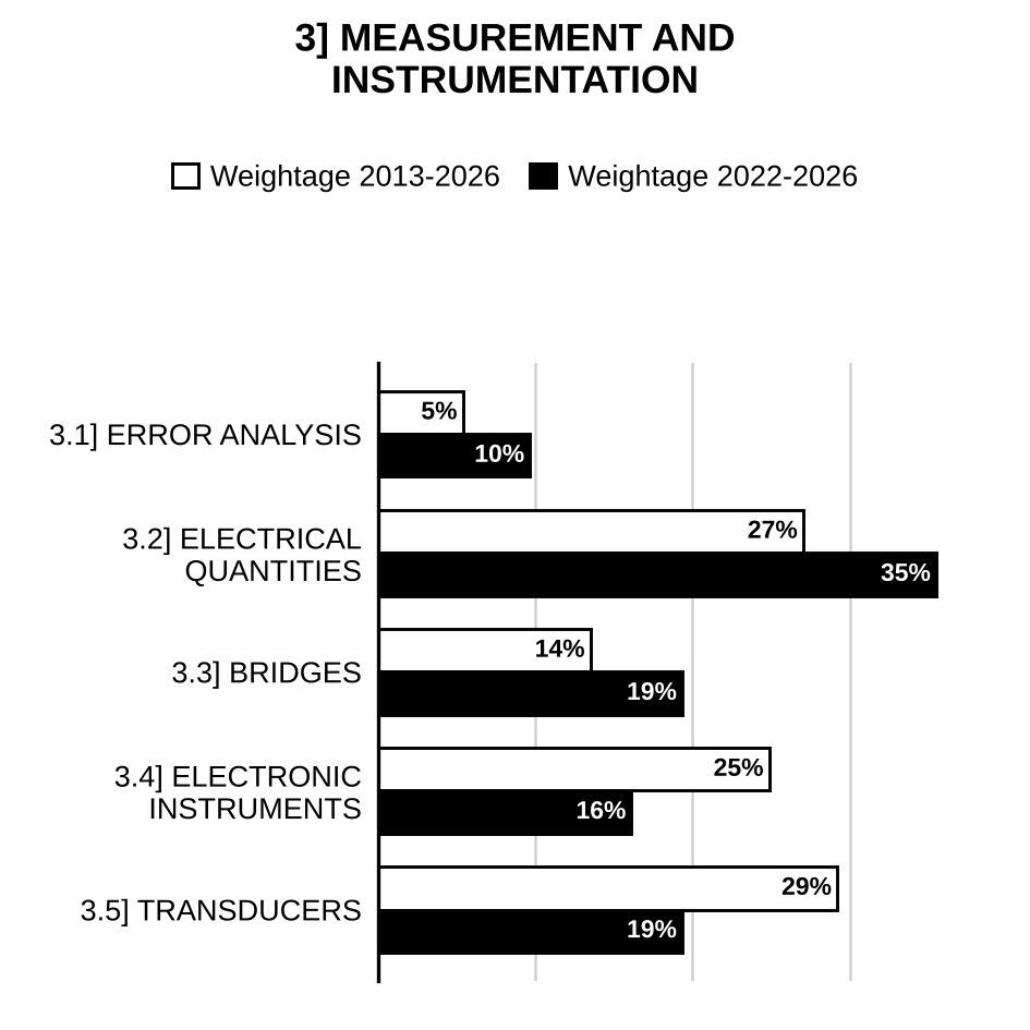
3.1] Error analysis
11 questions
To evaluate the value of resistance, the voltmeter and ammeter methods are used. The voltmeter reads 500 V with a probable error of and the ammeter reads 15 A with probable error of . Find out the probable error in the computed value of resistance. [2026/10m/1c]
For the circuit shown in the figure below give expression for the overall uncertainty in the value of combined resistance . Further, evaluate the overall uncertainty in the value of combined resistance , when individual values of the resistors are as
[Figure: Between two input terminals: in series with the parallel combination of and ; the far end of the parallel pair is wired back to the second terminal. denotes the combined resistance seen at the terminals] [2025/10m/1c]
In a parallel circuit, in one branch the current, and in the other branch the current, . Determine the total current considering the following errors: (i) Limiting error (ii) Probable error Comment upon the results as well. [2024/10m/2c]
An 820 Ω resistance with an accuracy of ± 10% carries a current of 10 mA. The current was measured by an analog meter of 25 mA range with an accuracy of ± 2% of full scale. Compute the power dissipated in the resistor and determine the accuracy of the result. [2016/10m/1a]
Giving classification of errors in measurement, explain these errors giving suitable examples. Explain how systematic errors can be minimised. [2013/5m/1a(i)]
A circuit consists of two branches in parallel. The current in one branch is A and in other is A. Determine the value of the total current , (i) considering the errors in and as limiting errors, (ii) considering the errors as standard deviations. Comment on the result. [2013/5m/1a(ii)]
(i) By giving suitable example explain clearly the difference between accuracy and precision. (ii) A power transformer was tested to determine losses and efficiency. The input power was measured as 3650 W and the delivered output power was 3385 W, with each reading in doubt by 10 W. Calculate the percentage uncertainty in the losses of the transformer and the percentage uncertainty in the efficiency of the transformer, as determined by the difference in input and output power readings. [2009/20m/2a]
Hicks clinical thermometer measures human body temperature. The instruction is to wait for half-a-minute before taking the reading. Is it because the measuring system is a: (i) zero order system with a pure time delay of half-a- minute? (ii) first order system with a time constant greater than half-a-minute? (iii) first order system with a time constant equal to half-a-minute? (iv) first order system with a time constant less than half-a-minute? Justify your answer. [2007/20m/1a]
Select any three of the following statements, read them carefully and identify the correct and the incorrect ones. Justify your answer using not more than 200 words in each case. The problem of drift may assume very serious problems in electronic instrumentation system. [2000/20m/200w/1b]
Define the terms ‘Dynamic error’ and ‘Resolution’ of an instrument. Explain how these can be determined in the laboratory. [1996/10m/4b(i)]
Justify the following statements: (i) It is advisable to measure a small quantity directly and not to deduce it as the difference of two individually measured large values. (ii) The plain Wheatstone bridge method is not suitable measurement of low-valued resistors. [1995/20m/1d]
3.2] Measurement of electrical quantities
35 questions
The following circuit is given for the measurement of voltage across a resistor as shown in the figure. Two voltmeters whose sensitivities are and respectively are used one by one for this purpose. Both voltmeters have a range of 0 – 100 V. Calculate the reading of each voltmeter.
[Figure: 200 V supply between terminals + (top) and − (bottom); series resistor from the + terminal to the top node; resistor from the top node to the bottom (−) line; a changeover switch from the top node connects either voltmeter or voltmeter across the resistor (the other ends of and go to the bottom line)] [2026/10m/2c]
An electrodynamometer wattmeter is used for power measurement in a 1- circuit. The load voltage is 200 V and load current is 20 A at power factor of 0.5 lagging. The wattmeter voltage circuit has a resistance of and inductance of 60 mH. Compute the percentage error in the wattmeter reading when pressure coil is connected on the load side. Given that the current coil resistance is , inductance is negligible and frequency is 50 Hz. Comment on the result. [2026/20m/3b]
A moving-coil instrument with a resistance of gives full-scale deflection for a current of 1 mA. A manganin shunt is used to extend its range to 1 A. Calculate the error caused by a 5 °C fall in temperature, when— (i) the manganin shunt is directly connected across the moving coil; (ii) a manganin resistance is used in series with the moving coil, before applying manganin shunt. Assume temperature coefficient of copper as 0.004/°C and that of manganin as 0.00015/°C. [2025/10m/2c]
The ohmmeter circuit has , , , and meter FSD = 50 μA.
[Figure: Ohmmeter circuit: battery on the left; from its upper terminal a wire to terminal A; the unknown resistance connected between terminals A and B; current (arrow to the right) flows from B through to node N. From N to the bottom (return) wire: (shown as an adjustable resistor) carrying (arrow down), and in parallel the meter branch in series with the meter M carrying (arrow down); marked across the meter branch ( and M). The bottom wire returns to the lower terminal of .]
Determine the ohmmeter scale reading at 0.5 FSD. [2024/10m/1c]
The disc in a single-phase energy meter rotates 1320 times when monitoring a 110 V, 3 A load at unity power factor over a period of 8 hours. Calculate the meter constant. If the meter makes 750 revolutions when measuring the energy supplied to a 110 V, 5 A load for 3 hours, determine the load power factor. [2024/10m/5b]
Two ammeters having resistances of 1 Ω and 2 Ω respectively give full-scale deflections with 200 mA and 250 mA respectively. Find the shunt to be connected with these ammeters to extend their range to 20 A. The range extended ammeters are connected in parallel and then placed in a circuit in which a total current of 15 A is flowing. Find the readings of the ammeters. [2023/20m/8b]
In a symmetrical three-phase system supplying a balanced load of 28 A at 400 V, a wattmeter reading is 5 kW, when its current coil is connected in the red phase and its voltage coil is connected between the neutral and red phase. Determine the instrument reading for the phase sequence RYB, if the voltage coil is connected between the blue and yellow phases. (The current coil remains unchanged) [2022/10m/1e]
The figure below shows a schematic diagram of shunt ohmmeter. It consists of a battery in series with an adjustable resistance and a d.c. measuring PMMC ammeter. The unknown resistance to be measured is connected across the terminals A–B. S is the off-on switch. Write down its design equations. What are your observations when the terminals A–B are shorted and open-circuited?
[Figure: Shunt ohmmeter: battery E in the left branch; from its top, adjustable resistance (current ) along the top wire to a junction; from the junction the basic meter (PMMC, internal resistance , current flowing down) goes down to the bottom wire; the top wire continues from the junction to terminal A. The bottom wire runs from terminal B through switch S back to the bottom of the battery. The unknown resistance is connected externally across terminals A and B (i.e. in parallel with the meter).] [2022/10m/3a(i)]
Determine the value of the resistor in series with the battery to adjust the full-scale deflection and the point (in %) of full scale at which 100 Ω will be marked on the scale. Consider the e.m.f. of internal battery as 2 volts, full-scale current of 2 mA and an internal resistance of 20 Ω. [2022/10m/3a(ii)]
A current of amps is passed through the circuit shown in figure. Determine the reading of each instrument if .
[Figure: A 1 mH inductor in series with a 1000 Ω resistor; the current i (arrow to the right) then passes through two ammeters in series, one marked MC (moving coil) and one marked MI (moving iron). An electro-static voltmeter V is connected across the 1 mH inductor and a second electro-static voltmeter V across the 1000 Ω resistor.] [2021/10m/1d]
A coil of 300 V moving iron voltmeter has a resistance of 500 ohms and an inductance of 0.8 H. The instrument reads correctly at 50 Hz AC supply and takes 100 mA at full scale deflection. What is the percentage error in the instrument reading, when it is connected to 200 V DC supply. [2021/10m/3c]
Explain the ratio error and phase angle error of current transformer. [2021/10m/5a]
Draw the circuit arrangement for power measurement in a 3-phase, 3-wire balanced supply and load using two-wattmeter method, and show that the power factor of the load is given by where and are powers indicated by Wattmeter 1 and Wattmeter 2, respectively. [2020/20m/2b]
A full-wave rectifier type ammeter displays a current reading of 5.55 mA r.m.s. when measuring the current waveform shown in the figure given below:
[Figure: Current waveform i against t: a symmetrical triangular wave starting from zero at t = 0, rising linearly to the peak (marked by a dashed line), falling linearly through zero to , rising again, and so on (equal positive and negative peaks, zero mean)]
Determine the true r.m.s. value of the current waveform and the error in the meter. [2019/5m/1d(ii)]
The magnetizing and loss component of exciting current of a current transformer rated 1000/5 A, are 15 A and 9 A respectively. The phase angle between secondary winding induced voltage and current is 40 degree. Determine the phase angle error of the transformer. [2018/10m/1d]
An energy meter is designed to have 80 revolutions of the disc per unit of energy consumed. Calculate the number of revolutions made by the disc when measuring the energy consumed by the load carrying 30 A at 230 V and 0.6 power factor. Find the percentage error if the meter actually makes 330 revolutions. Also specify whether the meter runs slower or faster. [2018/10m/2b(i)]
A wattmeter reads 5 kW when its current coil is connected in red phase and its voltage coil is connected between neutral and red phase of a symmetrical three-phase star-connected system supplying a balanced three-phase inductive load of 25 A at 440 V. What will be the reading of the wattmeter if the connection of the current coil remains unchanged and voltage coil is connected between blue and yellow phase? Hence determine the total reactive power in the circuit. [2018/10m/5b]
Why low resistances are usually constructed as four-terminal resistances? [2017/5m/1d(i)]
How can surface resistivity of insulating material be measured using direct deflection method? [2017/5m/1d(ii)]
A single phase, 240 V, 20 A, induction type watt-hour meter is working correctly. When tested at half load, rated voltage, and unity power factor, the disc rotates at 32 rpm. Determine the meter constant of the meter. Then, due to the alteration of the lag adjustment of the meter, the meter reads with −6.7% error at 0.8 p.f. lagging. What is the new phase angle between the supply voltage and the pressure coil flux because of this incorrect lag adjustment? [2017/15m/3c]
How a compensating coil can be utilized in reducing connection errors in an electro-dynamometer type wattmeter? [2017/10m/5c]
What are the sources of errors in an electrodynamometer type wattmeter? A dynamometer type wattmeter connected normally to read power in a 1-phase circuit indicates the value . A second reading is obtained when a capacitor of reactance equal to the pressure coil resistance is connected in series with the pressure coil. Show that the phase angle of the load can be obtained from the expression . [2015/20m/4b]
.
(i) Draw the basic circuit of an analog series ohmmeter to measure an unknown resistance . [2012/3m/5c(i)]
(ii) If the standard resistance and meter resistance add up to 20 kΩ, and the battery is of 2.0 V, determine the instrument indication, when . [2012/2m/5c(ii)]
(iii) What would be the resistance value marked for 0.5 FSD (full-scale deflection)? [2012/2m/5c(iii)]
(iv) What component should be connected and in which way to take care of falling battery voltage? [2012/1m/5c(iv)]
(v) When each time ohmmeter is used, what adjustment is recommended for accurate measurement? [2012/2m/5c(v)]
Explain, why the pointer of a single phase dynamometer type power factor meter remain in the same position even after the excitation source is switched off, that is, it does not come back to zero position. Explain the principle of operation of the power factor meter. How would the accuracy of such an instrument be affected by frequency and wave form variations. [2010/20m/4a]
Explain how the following adjustments are made in a single phase induction type energy meter: (i) Lag adjustment (ii) Adjustment for friction compensation (iii) Creep (iv) Overload compensation (v) Temperature compensation. [2009/20m/4a]
(i) Explain the construction of single-phase induction-type energymeter. (ii) A 230 V single phase watt hour meter has a constant load of 4 A passing through it for 6 hours at unity p.f. If the meter disc makes 2208 revolutions during this period, what is the meter constant in revolutions per kWh? Calculate the power factor of the load if the number of revolutions made by the meter are 1472 when operating at 230 V, and 5 A for 4 hours. [2004/20m/6a]
Select any three of the following statements, read them carefully and identity the correct and the incorrect ones. Justify your answer using not more than 200 words in each case: If a polyphase, load is supplied through ‘m’ conductors, the total power consumed is measured by adding the readings of ‘m’ wattmeters so arranged that current coil of a wattmeter is in each line and the corresponding pressure coil is connected between that line and a common point. If the common point is located on one of the lines, then the power may be measured by (m – 1) wattmeters only, irrespective of balanced/unbalanced load. [2003/20m/200w/1b]
Select any three of the following statements read them carefully and identify the correct and the incorrect ones. Justify your answer using not more than 200 words in each case For measurement of 3ϕ power using two wattmeters one of the wattmeters reads negative when the power factor angle is more than 60°. [2002/20m/200w/1b]
Explain with suitable diagrams, how one single phase wattmeter can be used to measure 3ϕ active and reactive power. Discuss the limitation of this method. [2002/20m/6a]
Why does an induction type energy meter creep? How is the creep prevented? [1999/10m/4a(i)]
The calibration constant of a 3-phase energy meter is 0.14 revolutions of disc per kwh. It is used with a potential transformer of ratio 11 KV/110 V and a current transformer of ratio 500 A/5 A. The test results are: Line voltage = 100 Line current = 5.25 A, Power Factor = 0.9 lagging, Time to complete 30 revolutions of discs =0 [?] sec. Determine the percentage error in the meter in terms of the actual energy consumed. [1999/10m/4a(ii)]
A half wave rectifier which prevents current flowing in one direction is connected in series with A.C. ammeter and a permanent magnet moving coil ammeter. The supply is sinusoidal. The reading on the A.C. ammeter is 10 A. Find the reading of the other ammeter. What would be the reading on the ammeters if the other half wave were rectified instead of being cut off? [1998/20m/2b]
a single element rectifying device is connected in series with a moving coil ammeter and a thermal ammeter and it is found that the circuit has a resistance of 100 Ω to current in one direction and infinitely large resistance to current in the opposite direction. If a sinusoidal e.m.f. of 10 V (r.m.s.) is applied to this circuit, what will be the reading of each instrument and what will be the power taken from the supply? [1998/20m/5a]
The secondary of a current transformer should never be kept open circuited. [1997/20m/200w/5d]
A 20 kΩ standard resistor and a test resistor are connected in series across a d.c. voltage source of negligible internal resistance. The voltages across , and the source are measured in turn by an accurate 0 – 120 V d.c. voltmeter. The readings obtained are 75 V, 21 V and 100 V respectively. Find the sensitivity of the d.c. voltmeter. [1995/20m/4a]

Preparing for Prelims too?
Our UPSC Prelims Topic-wise PYQ eBook covers every Prelims question with detailed explanations, so you can see exactly where UPSC asks from.
View the BookDownload Free Sample3.3] Bridge measurements
19 questions
A bridge consists of the following configurations: Arm : A choke coil of unknown resistance and unknown inductance Arm : A non-inductive resistance Arm : A non-inductive resistance Arm : A mica condenser with capacitance in series with a non-inductive resistance Bridge balance is obtained at 400 Hz with the following component values: , , , Assume that capacitor has a series resistance of . Calculate the resistance and inductance of the choke coil. Also sketch the phasor diagram for the bridge under balanced conditions, and evaluate factor of the choke coil. [2025/20m/3b]
Draw the connection diagram of a Schering bridge to measure the capacitance and dissipation factor. Write the balance equations and derive the formulae for finding the capacitance and dissipation factor. [2023/20m/2b]
The values of the components in the Maxwell bridge for balance condition are shown below in the circuit diagram. Write the balance equation and calculate the values of , and Q for the unknown sample coil:
[Figure: Maxwell bridge (diamond): supply 5 V AC, 100 Hz connected between the top and bottom corners. Top-left arm: . Top-right arm: unknown sample coil ( in series with , dashed box). Bottom-left arm: variable in parallel with variable . Bottom-right arm: . Detector D between the left and right corners.] [2022/20m/4b]
Derive the conditions of balance of an Anderson’s bridge and also draw the phasor diagram of the bridge under balanced condition. Determine the unknown quantities in terms of known parameters and comment on easy convergence of balance of the bridge. [2021/20m/4b]
An insulating material specimen is connected to arm AB of a Schering bridge. The arm BC has a non-inductive resistance of 140 Ω and arm CD has a non-inductive resistance of 208 Ω in parallel with a capacitor of 0.5 μF (loss-free). The arm DA has a loss-free capacitor of . If the bridge is supplied with 50 Hz a.c. voltage connected between terminals A and C, then draw a neat circuit diagram of the bridge and derive the balance condition of the bridge, and calculate the parameters , of the specimen and its loss angle (δ). [2020/10m/5b]
Which method is used to eliminate the effect of stray capacitances in a four-arm AC bridge? Describe with circuit diagram. [2018/20m/7b]
A Schering bridge, used to test a specimen, has the following bridge arms: arm ab contains the unknown capacitance () whose loss part is represented by a series resistance (), arm bc contains a non-inductive resistance () of 315 Ω, arm cd contains a variable capacitor () in parallel with a variable non-inductive resistance () and arm da contains a standard capacitor () of 150 pF. The supply is connected between a and c and the detector is connected between b and d. The specimen is tested at a frequency of 50 Hz, it is having a thickness of 6.3 mm and it is tested between electrodes each having a dimension of 0.15 m × 0.18 m. At balance, and . Find the capacitance, dissipation factor and relative permittivity of the specimen. Given: Permittivity of free space . [2017/15m/4c]
The a.c. bridge circuit shown below is used to measure the excitation frequency of the source and the resistance connected in arm of the bridge. Arm is parallel combination of and , arm is fixed resistor , arm is serial combination of and :
[Figure: Bridge ABCD drawn as a diamond (B top, A left, C right, D bottom) with four arm impedances (unlabelled boxes) AB, BC, CD and DA; detector G connected between A and C; source (a.c.) connected between B and D]
(i) Find the expression for the unknown resistance at balance. [2012/5m/7c(i)]
(ii) Find the expression for unknown excitation frequency at balance. [2012/5m/7c(ii)]
(iii) If , , , and , find the value of in kΩ and frequency of excitation in kHz. [2012/10m/7c(iii)]
.
(i) What are the difficulties associated with measurement of low resistances? [2011/5m/1a(i)]
(ii) Describe how low resistance is measured accurately by Kelvin’s double bridge. Derive the formula. [2011/15m/1a(ii)]
Why is a Schering bridge particularly suitable for measurement at high voltage? Draw high voltage Schering bridge line diagram, showing the high voltage transformer. The Wien bridge is used to measure the frequency of excitation voltage. Derive the frequency relation in terms of bridge elements. [2010/20m/7a]
A Wheatstone bridge has resistances , , , and in its four arms. The bridge is excited by E volts dc. Assuming that the ratio of arms and are equal, the bridge is initially balanced with equal to . A slight unbalance is created by . Show that the unbalance voltage, , is directly proportional to as long . What is the condition for maximizing the sensitivity? [2007/20m/8a]
“Bridges can be used for the determination of frequency in terms of values of various bridge elements”. If this is correct draw the bridge and derive condition for balance. Why and how are two resistances and capacitances made equal? Can this bridge be used for measurement of capacitance? [2006/20m/5b]
Select any THREE of the following statements, read them carefully and identify the correct and the incorrect ones. Justify your answer using not more than 200 words in each case:- Bridges are used to measure inductance of coils having different values of Q and capacitances are used therein to obtain the balance. [2004/20m/200w/1b]
Explain how frequency can be measured using four arm bridge arrangement. Derive balance condition for such a bridge. Mention the range of frequency measurement and accuracy of such measurement. If applied voltage is non- sinusoidal, will it be possible to balance this bridge? [2003/20m/6a]
One method of measuring a small capacitance is shown in fig. 1. and are equal high-quality variable air capacitors. is a fixed high quality capacitance of much smaller value than maximum value of (about 1/10 of ). The following two balances are obtained (i) With switch S open, at its maximum value and is adjusted for balance. (ii) With switch S closed, left unaltered and is adjusted to to get a new balance Prove that If R = 1000Ω, and are 1000 pF and pF and assuming the variable capacitors are readable to ± 5 pF with what accuracy could a capacitance of 1 pF be measured?
[Figure: Fig. 1: Bridge with four arms between a top node, left node, right node and bottom node: upper-left arm R and upper-right arm R (from the left and right nodes to the top node); lower-left arm: variable capacitor from the left node in series with fixed capacitor to the bottom node; lower-right arm: variable capacitor from the right node to the bottom node; detector D between the top node and the bottom node; bottom node earthed. From the junction of and , switch S in series with to earth. An ac source is connected across the left and right nodes; label W on the supply side.] [2000/20m/4a]
The bridge circuit, shown in the above figure, is balanced when S = 10 milli ohm, P = 1100 ohm, Q = 1000 ohm, q = 500 ohm and r = 0.1 ohm. Find the value of .
[Figure: Kelvin double bridge: battery with a series resistor (rheostat) on the left connected across the outer ends of two series chains; left chain (top to bottom): S, link r, ; right chain (top to bottom): P, Q; inner ratio arms p (from the junction of S and r) and q (from the junction of r and ) meet at a common point which is connected through the galvanometer to the junction of P and Q] [1999/20m/2c]
The circuit arrangement of an Owen Bridge for the measurement of the effective self inductance and resistance of an iron cored coil is shown in the figure below. Determine the balance conditions for the bridge and calculate the effective inductance and resistance of the coil if, for a frequency of 1000 Hz, the values of the circuit elements at balance are as follows: , ,
[Figure: Owen bridge drawn as a diamond: upper-left arm capacitor ; upper-right arm capacitor in series with resistor ; lower-left arm resistor ; lower-right arm the iron-cored coil (L, R); detector D between the top and bottom corners; a.c. source connected between the left and right corners] [1998/20m/4c]
The Fig. 3(b) shows the Wien’s bridge for measurement of frequency. Derive suitable expressions under balanced bridge condition. What should then be the relation between R and and between C and so that the excitation frequency is expressed as ?
[Figure: Fig. 3 (b): Wien bridge drawn as a diamond, supplied by a source of frequency f connected between the top and bottom corners; upper-left arm: resistor R in series with capacitor ; lower-left arm: resistor R in parallel with capacitor C; upper-right arm: resistor [?]; lower-right arm: resistor [?]; detector D between the left and right corners] [1997/20m/3b]
Justify the following statements: (i) It is advisable to measure a small quantity directly and not to deduce it as the difference of two individually measured large values. (ii) The plain Wheatstone bridge method is not suitable measurement of low-valued resistors. [1995/20m/1d]
3.4] Signal conditioning and electronic instruments
40 questions
A 1 V signal with a source resistance of is connected to an oscilloscope which has an input impedance of in parallel with . The coaxial cable has a capacitance . Calculate the oscilloscope terminal voltage () when the signal frequency is 100 Hz. Also determine the frequency at which is 3 dB below . [2026/10m/5b]
A frequency counter with an accuracy of is employed to measure frequencies of 100 Hz, 1 MHz and 100 MHz. Calculate the percentage measurement error in each case. What is the effect of time base on error? [2025/10m/5b]
A CRT has an anode voltage of 3 kV and its parallel deflecting plates are 2.5 cm long and 5 mm apart. The screen is 30 cm from the centre of the plates. Assume the gain of the amplifier through which input voltage is applied to the deflecting plates as 100. Calculate the following: (i) Beam speed (ii) Deflection sensitivity of the CRT (iii) Deflection factor of the CRT (iv) Input voltage required to deflect the beam through 5 cm. [2024/20m/3b]
The distributed capacitance of a coil is resonated at 10 MHz with 100 pF in parallel and is then again resonated at twice the frequency with 16 pF. Calculate its equivalent distributed capacitance and the inductance of the coil. [2022/10m/1d]
Write advantages, disadvantages and application of spectrum analyzer. [2021/10m/6c]
Due to some errors in the internal circuit of a differential amplifier, its differential mode gain is halved, while its common-mode gain does not change. Find the reduction in the CMRR of this amplifier in decibels. [2019/5m/1d(i)]
With the help of suitable circuit diagram and related equations, explain the principle of measurement of the unknown parameters of a low-impedance coil using a Q meter in series connection mode. [2019/10m/2c]
Draw the circuit diagram of an instrumentation amplifier and derive an expression for the voltage gain of this amplifier. How can this gain be varied? [2019/10m/4c]
Explain how the spectra of amplitude-modulated signal are displayed on a spectrum analyzer. [2018/10m/2b(ii)]
Explain in detail different types of frequency instabilities that cause difficulties in spectrum analyzers for display of narrow frequency ranges. A spectrum analyzer is designed using a 10-kHz, 3 dB filter and with a noise figure of 25 dB. What is the minimum detectable signal of this spectrum analyzer? What will be the power-level of the third-order intercept point, if this spectrum analyzer possesses a dynamic range of 86 dB? [2017/15m/7c]
With the help of a neat diagram, explain the functioning of a Ramp type Analog-to-Digital Converter. A Ramp type ADC makes use of a 1 MHz clock generator and a ramp voltage that increases from 0 – 1.25 V in 125 ms. Find the number of clock pulses counted into the register for an input of 0.75 V. [2016/10m/6a]
A 500 Hz triangular wave with a peak amplitude of 40 V is applied to the vertical deflecting plates of a CRO having a vertical deflection sensitivity of 0.1 cm/V. Another 250 Hz sawtooth wave of 50 V is applied to the horizontal plates having a horizontal deflection sensitivity of 0.08 cm/V. Assuming the two inputs are synchronized, sketch the waveform displayed on the CRO. [2016/10m/7a]
Name the different types of CROs and mention their applications. Find the velocity of electrons that have been accelerated through a potential of 2000 V in a CRO. [2015/10m/1c]
Explain the working of a successive-approximation type digital voltmeter using a block diagram. [2015/10m/2c]
Explain the direct connection method of measurement of of a coil. Name the sources of error in such measurements. Compute the value of self-capacitance and inductance of a coil when the following measurements are made: At frequency 2 MHz, the tuning capacitor is set at 450 pF When the frequency is measured to 5 MHz, the tuning capacitor is tuned at 60 pF. [2015/20m/3b]
Describe with a block diagram the Ramp type analog-to-digital conversion. Also draw the block diagram of Ramp type digital voltmeter. [2014/20m/4a]
An analog transducer with a 0 – 10 V input is able to distinguish a change of 1 mV in its signal. Calculate (i) its resolution (ii) the minimum number of bits of ADC so that the digital output has almost the same resolution as transducer. Also calculate the (iii) quantization interval and (iv) number of decision levels. [2014/10m/5e]
Draw a functional block diagram and explain the working of a digital frequency meter. [2013/10m/4a(i)]
Describe the circuit and working of a wave analyser for audio frequency and Megahertz frequency. [2013/10m/4a(ii)]
What is a digital voltmeter? [2013/3m/6a(i)]
What are its advantages as compared to analogue voltmeters? [2013/3m/6a(ii)]
Listing different types of DVMs explain any one type for the measurement of current. [2013/4m/6a(iii)]
The circuit given below is made by three ideal operational amplifiers (op-amp):
[Figure: Three op-amp circuit. Op-amp 1: to the non-inverting (+) input; output at point ⓒ; resistor R from ⓒ to point ⓐ; the inverting (−) input of op-amp 1 is connected to ⓐ. Resistor from ⓐ to point ⓑ. Op-amp 2: to the (+) input; output at point ⓓ; resistor R from ⓑ to ⓓ; the (−) input of op-amp 2 is connected to ⓑ. Op-amp 3 (difference amplifier): ⓒ through to its (−) input, feedback from its output (point ⓔ) to the (−) input; ⓓ through to its (+) input, with from the (+) input to ground]
(i) Identify the name of the circuit. Comment upon its CMRR in comparison to op-amp. [2012/2m/8c(i)]
(ii) Find the expressions for voltages at points ⓐ, ⓑ, ⓒ, ⓓ and ⓔ. [2012/10m/8c(ii)]
(iii) If V and V and (voltage at point ⓔ) is 5 V, find the ratio of and , when overall gain is divided in the ratio of between first and second stage of the circuit. [2012/8m/8c(iii)]
.
(i) Briefly explain the working principle of a CRO with the help of a block diagram. [2011/10m/4a(i)]
(ii) The voltage across horizontal deflection plates of a CRO is , and that across vertical plates is . Prove that the trace on the screen is an ellipse. Determine the equation and interpret its meaning. [2011/10m/4a(ii)]
.
(i) Explain the carrier type a.c. signal conditioning system with the help of a block diagram. [2011/10m/6a(i)]
(ii) Describe the circuit of a 3-amplifier configuration of an instrumentation amplifier. Discuss how this offers a very high input impedance to the signal. [2011/10m/6a(ii)]
.
(i) Draw the block diagram of a microprocessor-based process control system, making use of data acquisition systems, sensor inputs, outputs connected to relays, DACs. Explain the scheme briefly. [2011/12m/6b(i)]
(ii) Design an interface to a microcomputer port using the LM334 temperature sensor and LM393 analog comparator. A logic 1 i/p should indicate a temperature of greater than 100 °F. (Corresponding voltage for this sensor is 3.11 volts.) [2011/8m/6b(ii)]
Explain the working principle of a “Harmonic Distortion Meter”. State some of its typical technical specifications. Also describe, how is the resistance measured with an electronic multimeter. [2010/20m/6a]
With the help of a block diagram explain the principle of working of a digital storage oscilloscope. Discuss advantages of this oscilloscope over analog oscilloscope. [2009/20m/5a]
Find the gain and approximate input impedance of the accompanying circuit. What is its bandwidth? What is this circuit called and for what purpose it is used as instrumentation? Analyze the following three Op-Amp based instrumentations amplifier and find its gain. What is its approximate input impedance? Assume that the Op-Amps are ideal.
[Figure 1 (after “… used as instrumentation?”): Op-amp voltage follower: input to the non-inverting (+) input; output connected directly back to the inverting (−) input; output ]
[Figure 2 (after “… input impedance?”): Three op-amp instrumentation amplifier: input applied between the + input of OA I (top) and the + input of OA II (bottom); a variable resistor [?] connected between the − inputs of OA I and OA II; feedback resistor [?] from the output of OA I to its − input and an equal resistor [?] from the output of OA II to its − input; the output of OA I goes through to the − input of OA III, and the output of OA II goes through to the + input of OA III; from the output of OA III to its − input and from its + input to ground; output terminal at the output of OA III] [2007/20m/5b]
Explain how the SCADA systems are techno economically feasible for Indian power systems. Point out the differences between loose-coupled SCADA system and tight-coupled SCADA system. Draw the diagrams of direct digital control system for power systems. [2005/20m/3b]
With a simple block diagram, explain basic swept receiver spectrum analyzer. List the spectra of different signals applied to the spectrum analyzer for analysis. [2005/20m/6a(i)]
Draw basic elements of a function generator and its output waveforms. [2005/20m/6a(ii)]
Draw a block diagram of Remote Terminal Unit (RTU), having different components/subsystems, communication bus etc. Write the functions it generally carries out. Briefly explain the distributed control system. Bring out the features of Data Highway. [2004/20m/3b]
Select any THREE of the following statements, read them carefully and identify the correct and the incorrect ones. Justify your answer using not more than 200 words in each case. It is necessary to use preamplification and filtering before data processing. [2001/20m/200w/1b]
Select any three of the following statements, read them carefully and identify the correct and the incorrect ones. Justify your answer using not more than 200 words in each case. One disadvantage of magnetic tape recorder is that its characteristics limit its use at higher frequencies. [2000/20m/200w/5b]
Discuss the merits and demerits of using counters in digital measuring instruments. [1999/20m/1d]
Two sinusoidal signals of equal amplitude and frequencies and (Hz) are applied simultaneously to vertical and horizontal deflecting plates respectively of a CRO. Sketch the Lissajous patterns that appear on the CRT screen, when. (i) (ii) ; and (iii) kHz with a phase difference of 90° between the two signals. If now, the control grid electrode is subjected to an additional sinusoidal signal of 10 kHz and of such amplitude that the grid is driven into cut-off state for part of its signal cycle what will be the change in the pattern displayed for part (iii)? [1997/20m/1c]
Using an RTD with 0.00251/°C coefficient and R (25°C) as 1000 Ω, design a Wheatstone bridge with an OP-AMP arrangement to provide a 0 to 10 V signal for a temperature span of 25°C to 125°C. [1996/20m/4a]
Give two examples each of active and passive transducers. Suggest suitable signal conditioning circuits for the same. [1996/10m/4b(ii)]
Give the block diagram of a typical modern digital counter and show how it is used to measure the frequency of a given test signal. What other categories of measurement can be performed using a digital counter? [1995/20m/4b]
3.5] Transducers
41 questions
A thermistor has a resistance of at ice point and at 60°C. The temperature-resistance relationship is given by . Evaluate the constants and . Also calculate the range of resistance to be measured if the temperature varies from 70°C to 120°C. [2026/10m/4c]
A quartz piezoelectric transducer having a capacitance of 3000 pF and voltage sensitivity of 0.06 V-m/N has a resistance of . The impedance of the measuring system has a capacitance of 300 pF in parallel with a resistance. A force as shown in the figure is applied across the transducer: Find the voltages just before and after . [Permittivity of quartz is ].
[Figure: Force (N) versus : rectangular pulse of height 0.2 N from to , zero thereafter] [2025/10m/4c]
The capacitance of a piezoelectric transducer is 2000 pF and charge sensitivity is . Assume the capacitance of the connecting cable as 150 pF, when the oscilloscope used for readout has a readout input resistance of 1 MΩ with parallel capacitance of 100 pF. Calculate the following: (i) Sensitivity of transducer alone (ii) High frequency sensitivity of the entire measuring system (iii) Lowest frequency that can be measured with 5% amplitude error by the entire system (iv) Value of the external shunt capacitance that can be connected in order to extend the range of 5% error down to 20 Hz. [2024/20m/4a]
A resistive strain gauge, with a gauge factor 2.2, is cemented on a rectangular steel bar with the elastic modulus, . The width and thickness of the steel bar is 3.5 cm and 0.55 cm respectively. An axial force of 12 kN is applied. If the nominal resistance of the strain gauge is 100 Ω, determine the change in resistance of the strain gauge. [2023/10m/5b]
A resistance strain gauge having a resistance of 100 Ω and gauge factor of 2 is connected in series to a load resistance of 200 Ω across 24 volts. The modulus of elasticity is . Calculate the change in output voltage due to the applied stress of . [2022/10m/2c]
A pulse is applied to a piezo-electric transducer for a time T. Prove that in order to keep the undershoot of the response to a value within 5%, the value of time constant should be approximately 20T. [2021/10m/5c]
Why are strain gauges made with high value of gauge factor ()? Write the expression for gauge factor in terms of change in resistance and strain. If a strain gauge with a gauge factor of 2 is bonded on a steel structure which is subjected to a stress of and the modulus of elasticity of steel is , then what is the percentage change in the value of the strain gauge resistance due to this applied stress? [2020/10m/1c]
The resistance-temperature characteristic of a thermistor is given by where is the resistance of the thermistor at reference temperature, and is the resistance at the measured temperature, T. If the value of β is 4000 K and the resistance of the thermistor is 200 kΩ at −100 °C, find the value of resistance at 400 °C. Also find the ratio of two resistances. If platinum resistance temperature detector (RTD) is used over the same temperature range, then what will be the ratio of RTD resistances on the above-referred two temperatures? [2020/20m/3a]
With the help of a neat diagram, explain the working principle and characteristics of a linear variable differential transformer (LVDT). Why is the frequency of excitation in primary winding kept very high as compared to frequency of the signal detected? Write three advantages and disadvantages of LVDT also. [2020/20m/7a]
With the help of a suitable diagram and equations, describe the principle of operation of a differential capacitive displacement transducer. In what way is it better than a normal capacitive displacement transducer? Determine the output voltage of this differential transducer when it is connected in an AC bridge. [2019/20m/7b]
Why temperature compensation is needed in strain gauges? A four arm DC Wheatstone bridge is designed using a single active gauge. How can a dummy gauge be employed here to achieve temperature compensation? [2017/10m/8c(i)]
A resistance wire strain gauge with nominal resistance 350 Ω and gauge factor 2 is fastened to a steel bar. The modulus of elasticity of steel is . What is the stress applied to the steel bar if strain gauge resistance becomes 350.5 Ω? [2017/5m/8c(ii)]
Show that the maximum non-linearity on account of loading of a linear potentiometer can be expressed as of f.s.d. for . [2016/20m/4a]
(i) An accelerometer has an input range of 0 – 100 m/s². It has a mass of 10 g and works on a frequency of 10 Hz. Find the range for the displacement transducer used to measure the displacement of the accelerometer. (ii) 1. State and explain Nyquist criterion. 2. An information signal is sampled. Calculate the minimum sampling rate that will be needed to recover the signal back from its samples. [2016/10m/5e]
With the help of a neat diagram, explain the working of an LVDT. Give its characteristics, advantages and applications. Explain the role of phase sensitive detector used for signal conditioning of LVDT. [2016/15m/6b(i)]
An LVDT is connected to a 10 V voltmeter through an amplifier of gain 100. An output of 2 mV appears across the terminals of the LVDT when the core crosses a distance of 0.5 mm. Find the sensitivity of the LVDT and that of the whole set-up. The used voltmeter has 100 divisions and th of a division can be read accurately. Find the resolution of the instrument in mm. [2016/5m/6b(ii)]
Explain the working of an LVDT with a Bourdon tube for the measurement of pressure. [2015/10m/1d]
Explain the function of piezoelectric crystal as transducer. Specify its use in (i) Kitchen lighter (ii) Ultrasound diagnostic equipments (iii) Industrial cleaning machines. [2014/10m/1c]
LVDT with bellow is used for measuring the pressure. Draw the circuit diagram of LVDT-bellow system. [2014/6m/6a(i)]
The sensitivity of LVDT-bellow system is 40 V per mm. The bellows are deflected by 0.15 mm by a pressure of N per . Determine the pressure when the output voltage of LVDT is 3.9 V. [2014/14m/6a(ii)]
What do you mean by Thermistor? Explain briefly resistance-temperature characteristic curve of Thermistor and compare the same with thermocouple. [2013/10m/5e]
Describe the functioning of a charge amplifier using an OPAMP with piezoelectric transducer used at the input for measurement of displacement. [2013/10m/7a(i)]
Derive the expression for the transfer function and draw its curve showing frequency response. [2013/10m/7a(ii)]
.
(i) The transfer function of a thermocouple relating output voltage to temperature is given by Put the transfer function in standard format and find the values of characterising parameters of the thermocouple. Determine the thermocouple output voltage at s, when the thermocouple kept at ambient temperature of 20 °C at s is taken to a water bath kept at 80 °C. [2012/7m/1c(i)]
(ii) Comment upon ‘linearity’ and ‘sensitivity’ of thermistors in comparison to thermocouples. [2012/2m/1c(ii)]
(iii) Why is ‘lead wire compensation’ not required for thermistors? [2012/1m/1c(iii)]
The equivalent model of a piezoelectrical crystal is shown below:
[Figure: Current source (arrow upwards) in parallel with resistor and capacitor ; output voltage taken across the parallel combination at two output terminals]
(i) Derive the transfer function relating output voltage to input displacement . Arrange it in standard form and identify the expression for characterising parameters. The charge developed in piezoelectric crystal is related to by a constant . [2012/10m/3b(i)]
(ii) “Piezoelectric transducers cannot be used to measure static displacement.” Comment upon the statement. State the reason based on the transfer function derived in Part (i). [2012/2m/3b(ii)]
(iii) If the lower range of frequency for displacement measurement is 5 kHz with 5% inaccuracy, what is the lower range of frequency for 2% inaccuracy? [2012/8m/3b(iii)]
.
(i) What are capacitive transducers? [2011/5m/7a(i)]
(ii) What are the different uses of capacitive transducers? [2011/5m/7a(ii)]
(iii) A pressure-measuring instrument uses a capacitive transducer having a spacing of 4 mm between its diaphragms. A pressure of produces an average deflection of 0.25 mm of the diaphragm of the transducer. The transducer had a capacitance of 300 pF before application of the pressure and was connected to an oscillator circuit having a frequency of 100 kHz. Determine the change in frequency of oscillator after the pressure is applied to the transducer. [2011/10m/7a(iii)]
Why is a excited by high frequency and low voltage? Derive the output, , in terms of excitation voltage, winding resistance and inductances. A bridge has resistors in its four arms. in arm , in arm , dummy gauge in arm , and active gauge in arm . If a strain of 1250 m/m is applied, find the bridge offset voltage across if the bridge is supplied with a voltage of 12 V across . Assume, ohm and ohm has gauge factor (). [2010/20m/1a]
(i) How is the differential output taken from an inductive transducer? Explain the advantages when inductive transducers are used in push-pull configuration. (ii) A LVDT has an output of 6 V rms when the displacement is m. Determine the sensitivity of this instrument in volt/mm. A 10 V voltmeter with 100 scale divisions is used to read the output. Two tenths of a division can be estimated with ease. Determine the resolution of the voltmeter. The above arrangement is used in a pressure transducer for measuring the deflection of a diaphragm. The diaphragm is deflected by m, by a pressure of 1000 . Determine the sensitivity and resolution of this instrument. [2009/20m/7a]
Enumerate the different kinds of head type flow meters used in the industry. What kinds of restrictions are placed in the flow path for flow measurement? Develop the relationship between flow and pressure differential from physical principles. Why is it that a rotameter is considered a standard in flow measurement? [2007/20m/1b]
Discuss the physics of piezo-electric phenomena. Draw the equivalent circuit of a piezo-electric transducer and derive the output voltage, of transducer with applied force F. Point out the four materials which exhibit the piezo-electric phenomena. Also write its applications. A piezo-electric pressure transducer having a charge sensitivity of C/N is connected to a charge amplifier, the gain being set to 5 mV/pC. The amplifier output is connected to an ultraviolet chart recorder whose sensitivity is set to 25 mm/volt. Determine the overall sensitivity. [2007/20m/4a]
“Thermistors have a Negative-Temperature-Coefficient”. If this is correct discuss Explain their working, construction and applications. Compare resistance-temperature characteristic of a typical thermister and platinum. [2006/20m/1b]
Select any three of the following statements, read them carefully and identify the correct and the incorrect ones. Justify your answer using not more than 200 words in each case. Transducers are sensors having many classifications, advantages and applications. [2005/20m/200w/1b]
Give the construction, principle of working and apperceptions of an LVDT. [2000/20m/8a]
The output of a LVDT transducer is 0.5 V at a frequency of rad./sec. Determine the output if the frequency deviates by 10%. The time constants of primary and secondary circuits are 5 ms and 2 ms respectively. [1999/20m/4b]
Select any three of the following statements, read them carefully and identify correct and incorrect ones. Justify your answer using not more than 200 words in each case: Shaft encoders are extremely useful for the measurement of singular displacement. [1999/20m/200w/1b]
Draw a schematic diagram and discuss how the thickness of foil can be measured by microwave sensors. [1999/20m/12c]
The output of an LVDT is connected to a 10 V voltmeter through an amplifier with a gain of 500. An output of 2.5 mV appears on the terminals of LVDT, when the core moves through a distance of 0.5 mm. Calculate the sensitivity of LVDT and that of the whole set-up. The voltmeter scale has 100 divisions and the scale can be read to 1/5 of a division. Calculate the resolution of the instrument in mm. [1997/20m/3c]
Give a typical set up for measuring the strain of a cantilever beam, with temperature compensation. [1996/10m/1d(ii)]
Using an RTD with 0.00251/°C coefficient and R (25°C) as 1000 Ω, design a Wheatstone bridge with an OP-AMP arrangement to provide a 0 to 10 V signal for a temperature span of 25°C to 125°C. [1996/20m/4a]
Give two examples each of active and passive transducers. Suggest suitable signal conditioning circuits for the same. [1996/10m/4b(ii)]
A thermo-electric sensor with a time constant of 50 ms is used to record the temperature of a furnace. Assuming that the furnace temperature varies sinusoidally between the two limits 300°C and 500°C with a frequency of 2 Hz, determine the limits of the temperature as recorded from the sensor. Indicate a method of reducing the resultant error. [1995/20m/4c]

Strengthen your GS papers
Our UPSC Mains Topic-wise & Year-wise PYQ eBook (2013–2026) maps every GS question to the syllabus, so you know what UPSC asks and how often.
View the BookDownload Free Sample« Previous: Microprocessors and Microcomputers | Next: Power Systems: Analysis and Control »
Back to: Electrical Engineering Optional PYQs – Topic-wise
Last updated: 30 October 2026