
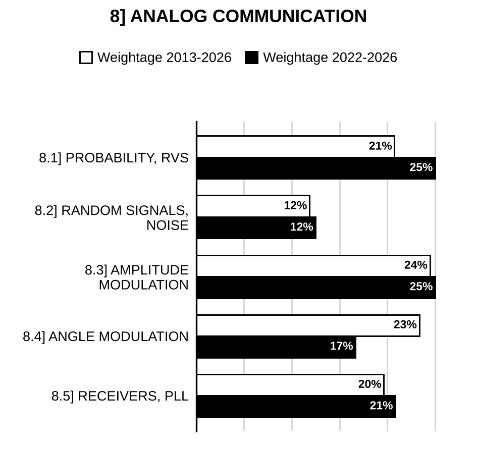
Here are all 148 Analog Communication questions asked in UPSC Electrical Engineering Optional Paper I from 1995 to 2026, arranged under the 5 topics of the official syllabus. Within each topic the latest questions come first.
Each question ends with a code such as [2024/15m/3b] – the year, the marks, the word limit (where UPSC set one) and the question number in the paper.
8.1] Probability and random variables
21 questions
A discrete random variable has two possible values or with probabilities and , respectively. The probability density function of is shown in the figure: If , where , are statistically independent and identically distributed random variables, what is the probability distribution function of ?
[Figure: PDF of versus : an impulse of height (weight) at and an impulse of weight at ] [2026/10m/5d]
Show that for a binomial random variable, the mean is given by and the variance is given by , where gives the number of trials and gives the probability of successes. [2025/10m/5d]
Two statistically independent Poisson random variables and with respective parameters and are added to form . Show that the random variable Y is Poisson distributed with parameter . [2023/10m/7b(i)]
Derive the relationship between Binomial and Poisson random variables when Binomial distribution becomes equal to the Poisson distribution. [2023/10m/7b(ii)]
X and Y are two independent random variables with probability density functions given by and (i) Determine A. (ii) Determine the probability density function of . [2022/20m/7b]
Let the measurement error of a physical quantity be defined by a random variable X and its density function as follows: Determine the value of ‘K’ and find the probability that a random error in measurement is less than 1/2. [2021/10m/6c]
(i) Which type of probability density function is applicable in case of calculating errors with aiming of missiles/projectiles, if errors in each of the two rectangular coordinates have independent Gaussian probability density functions? Find its mean, mean square value, variance and its cumulative distribution function. (ii) Suppose an archer shoots at a target, 3 m in diameter for which the bull’s eye is centered on the origin of an XY coordinate system. The position at which any arrow strikes the target is a random variable having an X-component and a Y-component. It is determined that the standard deviation of these components is m, i.e. Assume that the X and Y components of the hit position are independent Gaussian random variables. What is the type of random variable that can be assigned to the distance of origin from the hit position (i.e. the miss distance)? Write its probability density function and find the mean value, its standard deviation and the probability that the target will be missed completely. [2020/20m/8b]
Assuming that X is a Gaussian random variable with m = 0 and σ = 1, find the probability density function of the random variable Y given by . [2019/10m/5c]
Discuss the properties of a probability density function. What additional features a normal distribution has? [2017/10m/2c]
A random variable has an exponential probability function given by , where and are constants. Find (i) the relationship between and , and (ii) the distribution function of . [2014/10m/5d]
The two random variables and are independent and identically distributed each with a Gaussian density function with mean equal to zero and variance equal to . If these two random variables denote the coordinates of a point in the plane, find the probability density function of the magnitude and the phase of that in polar coordinates. [2014/20m/7b]
Evaluate whether the following function given by expression is a probability density function (PDF). [2012/12m/5e]
For the probability density function of a random variable with ranging between to , find the distribution function value of and the probability that lies between 0 and 1. [2010/6m/4c(iii)]
Explain the mathematical expressions for statistical average, mean, variance and correlation coefficient of a random variable. [2009/6m/1d(i)]
Define conditional probability and random variable. [2007/5m/4b(iii)]
In a certain communication system, the message is coded into binary digits 0 and 1. After coding, the probability of a 0 being sent is 0.45, while the probability of a 1 being sent is 0.55. In the communication channel, the probability of a transmitted 0 being converted into a 1 at the receiver is 0.1, while the probability of a 1 being distorted into a 0 is 0.2. Find: (i) the probability that a received 0 was transmitted as a 0, and (ii) the probability that a received 1 was transmitted as a 1. [2007/20m/5d]
Two random variables X and Y have the joint Pdf Where A is a constant. Evaluate A and determine the marginal pdfs and draw the corresponding graphs. [2006/10m/1d(i)]
Find the mean, the mean square, and the variance of the Gaussian random variable with the pdf [2006/20m/7b]
Three regular dice are thrown. Assign probabilities to the following events. The sum of the points appearing on three dice is 4; 9; and 15. [2005/10m/6b(i)]
Explain central limit theorem. [2005/10m/6b(ii)]
The joint probability density of the random variables X and Y is in the range and and f(x, y) = 0 otherwise. (i) Find the value of the constant K. (ii) Find the probability density f(x), the probability density of X independently of Y. (iii) Find the probability (iv) Are the random variables dependent or independent? Justify. [2004/20m/4b]
8.2] Random signals and noise
23 questions
A three-stage cascade amplifier given below receives a noise power of . What will be the output noise power? where and are the noise figure and gain of the amplifier.
[Figure: Cascade of three amplifiers: input noise power → amplifier 1 (, ) → amplifier 2 (, ) → amplifier 3 (, ) → output noise power ] [2026/10m/6c]
Find the temperature of the attenuator in the system shown in the figure below so that the overall noise figure of the system does not exceed 3.5 dB. The attenuator introduces a loss of 3 dB.
[Figure: Cascade of three blocks: Attenuator (loss = 3dB) → Amplifier (Gain = 1000, Noise figure = 1.5 dB) → Mixer (Gain = 100, Noise figure = 8 dB).] [2023/10m/8b(ii)]
Consider the system shown in Figure 8(b)(ii). The signal is defined by: The low-pass filter has unity gain in the passband and bandwidth W, where . The noise is white with two-sided power spectral density . Determine the signal-to-noise ratio of .
[Figure: Figure 8(b)(ii): Block diagram: and (from below) enter a summer Σ; its output passes through a block, then a second block, then a Low-pass filter, giving the output .] [2022/10m/8b(ii)]
A 3-stage amplifier has stages with the following specifications:
| Stage | Power Gain | Noise Figure |
| 1 | 10 | 2 |
| 2 | 25 | 4 |
| 3 | 30 | 5 |
Calculate the overall power gain and noise figure in dB and the noise temperature. Assume matched conditions. [2019/10m/8b]
Differentiate between stationary and non-stationary random processes. Give the properties of the first- and second-order distribution function of stationary random processes. [2017/10m/8c]
Write a short note on white noise. [2016/10m/7c]
Show that the Wiener-Hopf filter is practical only when the input SNR is small. [2013/20m/8b]
A receiver, connected to an antenna of resistance 50 ohms, has an equivalent noise resistance of 30 ohms. Find the noise figure of the receiver in dB. [2011/20m/8c]
Determine the power density spectrum of the noise voltage across the terminals of the circuit shown in Fig. 3:
[Figure: Fig. 3 – Three parallel branches connected between the top line (terminal a) and the bottom line (terminal a′): left branch 1 Ω resistor in series with 1 H inductor; middle branch 1 F capacitor; right branch 2 Ω resistor in series with 1 F capacitor] [2010/10m/1d(ii)]
Determine the noise bandwidth of the first-order RC integrator with cut-off frequency . Define the term noise bandwidth. [2010/5m/5d(ii)]
Explain, using analytical expressions, stationarity, time averages and ergodicity. [2009/9m/1d(ii)]
List the sources of noise in bipolar transistor. [2007/10m/1d(i)]
A 100 kΩ resistor is connected in parallel with a 100 pF capacitor Determine the effective noise bandwidth and the noise voltage appearing at the terminals of the combination at 27° C. [2007/10m/1d(ii)]
A radar receiver has a low noise RF amplifier of noise figure 6 dB and gain 20 dB followed by a mixer of noise figure 6 dB and conversion loss of 6 dB. If the noise figure of IF pre-amplifier is 3 dB with a gain of 26 dB and that of IF main amplifier is 10 dB, obtain the noise figure of the receiver and its noise temperature. [2007/20m/7b]
A white-noise current source having a power spectral density is filtered by a narrow band, parallel single-tuned circuit having a resonant frequency at and a 3-dB bandwidth . Find the output voltage noise power. [2006/10m/4b(ii)]
How much noise voltage is generated in a 1 MΩ resistance at 27°C over a 10 kHz bandwidth? List the sources of noise in an amplifier. [2005/5m/5b(ii)]
A cable transmission system with a loss of (L) 240 dB and has m = 6 equal length repeater sections and the SNR at the destination dB. Find the new value of if (a) m is increased to 12 and (b) m is decreased to 4. Express your answer both in ratio and in dB. [2004/10m/1d(i)]
White Gaussian noise of two sided spectral density is applied to a low pass (RC) filter having a 3 dB cut-off frequency of 1 kHz. Find the output noise power. [2003/5m/6c(i)]
The received signal is r(t) = s(t) + n(t) where s(t) is the signal and n(t) is the noise signal. The signal process is random with an autocorrelation . The noise is a sample function of a random process with auto-correlation . If the two processes are having zero mean value and are independent of each other determine the autocorrelation and total power of r(t). [2003/15m/6c(ii)]
In a TV receiving system the pre-amplifier (mounted on the aerial) has a gain of 20 dB and a noise factor of 6 dB and the cable between the pre-amplifier and the receiver has an attenuation factor of 3 dB. While the RF and IF stages or the receiver have a total gain of 90 dB and a noise figures of 3 dB (RF stage) and 13 dB (IF stage) Determine the system overall noise figure. [2002/20m/6c]
Define spectral density and auto-correlation function for the measurement of noise. Find out the spectral density and auto-correlation function of the output when white noise with spectral density is applied to a low pass RC filter. Derive the expressions used. [1999/30m/10a]
An antenna having a 10°K noise temperature feeds a low noise amplifier of 4°K noise temperature and 20 dB gain. This is followed by another amplifier of 4 dB noise figure and 30 dB gain. Find the overall noise figure and noise temperature of the system. [1998/20m/10a]
Explain what you understand by shot noise, signal-to-noise ratio and noise figure. When might the noise-figure be a more suitable piece of information than the equivalent noise resistance? The first stage of a 2-stage amplifier has a voltage gain of 10, a 500 Ω input resistor, a 1500 Ω equivalent noise resistance and a 30 k ohm output resistance. For the 2nd stage these values are 20, 80 kΩ, 10 kΩ and 1 MΩ respectively. Calculate the equivalent input-noise resistance of the two-stage amplifier. [1995/20m/10a]

Preparing for Prelims too?
Our UPSC Prelims Topic-wise PYQ eBook covers every Prelims question with detailed explanations, so you can see exactly where UPSC asks from.
View the BookDownload Free Sample8.3] Amplitude modulation
38 questions
A sinusoidal modulating signal of frequency produces an AM signal: , where is carrier frequency. Here, and . This is applied to an ideal envelope detector which produces an output . (i) Determine the Fourier series representation of . (ii) Also determine the ratio of second harmonic amplitude to fundamental amplitude in . [2025/20m/8b]
An AM signal is applied to the system shown in the figure. Show that the message signal can be obtained from the square-rooter output :
[Figure: Block diagram: → Squarer → → Low-pass filter → → Square rooter → ; with and .]
Assume that for all , the message signal is limited to the interval , and the carrier frequency . [2024/10m/6a(i)]
A signal x(t) is described as Show that this is an Amplitude modulated signal. Find: (i) the ratio where is power in side bands and is power in carrier. (ii) the power efficiency in this AM signal. [2023/10m/5c]
A 300 W carrier is modulated to a depth of 70%. Calculate the total power transmitted in case of Vestigial Side Band (VSB) modulation. Assume 15% of the other side band is transmitted along with wanted side band. Also find the saving in power when compared to Double Side Band (DSB) transmission. [2023/10m/8b(i)]
An audio frequency signal is used to amplitude modulate a carrier of . Determine: (i) the modulation index (ii) the amplitude of each sideband frequency (iii) the bandwidth required (iv) total power delivered to the load of 500 Ω (v) and draw the frequency spectrum. [2022/10m/5d]
A transmitter with a 10 kW carrier transmits 11.2 kW when modulated with a single sine wave. Calculate the modulation index. If the carrier is simultaneously modulated with two other sine waves also at 50% modulation, calculate the total power transmitted. [2021/10m/5d]
Vestigial sideband modulated wave is to be generated by passing a double sideband suppressed carrier wave through a filter. Show that the transfer function H(f) of this filter must satisfy the condition , where is constant. Assume the message signal to be m(t). [2020/10m/5d]
An SSB transmitter transmits with 10 kW power. This transmitter is to be replaced by a standard amplitude modulated signal with same total power content. Determine the carrier power and each sideband power, when the percentage modulation is 80%. [2018/10m/2c]
The antenna current of a transmitter is 11.5 amperes, when it is modulated to a depth of 45% by an audio wave. The current enhances to 12.5 amperes on account of simultaneous modulation by another audio sine wave. Find the modulation index of the second audio wave. [2018/20m/4a]
Explain and differentiate between the single sideband (SSB) modulation and double sideband suppressed carrier (DSB-SC) modulation. Show the DSB-SC modulated waveform for any chosen baseband signal waveform and spectrum of the baseband and the DSB-SC modulated wave. [2017/20m/4a]
An amplitude modulated signal, viewed on an oscilloscope, has a crest voltage of 44 V peak-to-peak. The bottom (or trough) point of the wave measures 6 V peak-to-peak. Find the modulation factor, percentage modulation and peak-to-peak unmodulated carrier voltage. [2017/10m/5d]
Compare Amplitude Modulation (AM) and Frequency Modulation (FM). [2016/10m/5d]
Evaluate the maximum and minimum values of V(t) of the amplitude-modulated voltage signal defined as: . [2015/20m/8b]
(i) In an FM system, when the audio frequency (AF) is 500 Hz and AF voltage is 2.4 V, the deviation is 4.8 kHz. If the AF voltage is now increased to 7.2 V, what is the new deviation? If the AF voltage is raised to 10 V while AF is dropped to 200 Hz, what is the deviation? Evaluate modulation index in each case. (ii) If , determine AM transmission bandwidth and average transmitted power for the AM modulated signal assuming and (modulation index) = 0.6. What will be the values of and in the case of DSB transmission? [2012/20m/7c]
Specify the types of modulation used in the following and give reason for the same: (i) TV–video signal (ii) TV–sound signal (iii) Long-distance telephone system. [2011/15m/5d]
The RMS value of the antenna current before amplitude modulation is 10 A and after modulation is 12 A. Calculate the percentage modulation. Assume that there is no distortion. [2011/20m/8a]
A message signal containing the frequency components 100 Hz, 200 Hz and 400 Hz is applied to an SSB modulator together with a carrier at 100 kHz with only USB retained. The coherent detector employed at the receiver uses a local oscillator that gives a sine wave of frequency 100.02 kHz. 1. Determine the frequency components of detector output. 2. Determine the frequency components of detector output if only LSB is transmitted. [2010/10m/3c(ii)]
Establish the time-domain expression for the AM signal at 60% modulation level with modulating signal as and carrier as , and list out its Fourier transform. Find out the amplitude sensitivity constant, side-band powers and efficiency. [2010/10m/8c(ii)]
An AM wave is to be detected by a linear diode detector. 1. Find the time constant, . 2. Find the value of , if the capacitor used is 100 pF. [2009/8m/4c(i)]
Bring out the SSB spectrum with modulating signal and carrier is [2009/8m/7c(iii)]
Show that at 100% modulation index, power contained in one side band of AM system is of total power transmitted. [2007/10m/4b(i)]
A standard AM transmission, sinusoidally modulated to a depth of 30%, produces side frequencies of 4.928 and 4.914 MHz. The amplitude of each side frequency is 75 V. Determine the amplitude and frequency of the carrier. [2007/5m/4b(ii)]
Show that the signal is an SSB signal. Is it USB or LSB? Write an expression for the missing sideband. Obtain an expression for the total DSB-SC signal. [2006/10m/4b(i)]
Show that power contained in one sideband is 1/6 to the total power of amplitude-modulated signal at 100% modulation index. [2005/10m/4b(ii)]
In a trapezoidal pattern displaying modulation, the length of the long vertical side is 5 cm, and of the short vertical side, 2 cm. Determine the modulation depth. [2005/5m/5d(i)]
Describe ‘third method’ of generating an SSB-SC signal. [2005/10m/7b(i)]
Explain envelop detector circuit with input and output waveforms. [2005/10m/7b(ii)]
Can you detect a DSBSC signal using an envelope detector? By a suitable analysis, compare the same with coherent detection. [2003/15m/1d(i)]
A modulating signal, m(t) is given by . Determine the LSB and USB relations + LSB and USB if the carrier frequency is 1000 rad. [2003/5m/1d(ii)]
Distinguish between envelope detection and synchronous detection. Explain a Costas loop receiver for demodulating a DSBSC signal. Explain how the squaring circuit can also be used for synchronous detection. [2003/20m/7c]
.
(i) An AM modulator has output Determine the modulation index and efficiency. [2002/10m/4c(i)]
(ii) An upper sideband SSB modulator has the message signal . The unmodulated carrier is given by . Sketch the modulator output x(t). [2002/10m/4c(ii)]
A two-tone modulating signal modulates a carrier voltage . Find various frequency components present and corresponding modulation indices. Also obtain the amplitude of the signals present in each sideband and the bandwidths. [2001/20m/1d]
Show that the multiplication of a sinusoidal signal by a signal f(t) translates the whole frequency spectrum. Can we retranslate the spectrum to its original position? If yes how? [2001/20m/2a]
Show that the output of a balanced modulator using semiconductor diode is DSB-SC. [2001/20m/7b]
A signal is applied to the input of an average (diode) detector with load resistance R. The diode is characterized as for for Obtain an expression or low frequency component of the output voltage of the detector for [2000/20m/7c]
Consider a DSB-SC signal corresponding to a modulating signal x(t) of bandwidth B and a carrier signal . This DSB-SC signal forms the input in Fig. 11(a). Find the output and comment on the result.
[Figure: Fig. 11(a): Input Signal applied to both inputs of a multiplier (X) (the input is split and fed to the multiplier twice); multiplier output to an LPF (Cut-off 2 B); LPF output to a square-root block (); its output is the Output] [1998/20m/11a]
(i) What are the three main systems of SSB generation? Give the salient characteristics of each system. (ii) Prove that the balanced modulator produces an output consisting of side bands only, with the carriers removed. [1996/20m/10a]
Explain, with the help of block diagram, the principle of operation of an ISB transmitter. [1995/20m/10c]
8.4] Angle modulation
35 questions
The signal shown in the following figure is used once to frequency modulate a carrier and once to phase modulate the same carrier: Find the relation between and such that the maximum phase of the modulated signal in both the cases is equal, where and are phase and frequency sensitivities, respectively of the modulator.
[Figure: versus : rises linearly from 0 at to 1 at ; constant at 1 from to ; at drops to −1 and stays at −1 from to ; returns to 0 at and is zero thereafter (dashed lines mark levels 1 and −1 and )] [2026/10m/7c]
An FM signal with a frequency deviation of 15 kHz at a modulation frequency of 5 kHz is applied to two frequency multipliers connected in cascade. The first multiplier multiplies the frequency by 1.5 times and the second multiplier multiplies it by 4 times. Determine the frequency deviation and the modulation index of the FM signal obtained at second multiplier output. Also compute the approximate bandwidth of the FM signal. [2026/10m/8c]
How can linear pre-emphasis and de-emphasis filters be employed to improve the performance of an FM system? Is the improvement in output SNR dependent on both the frequency responses of the pre-emphasis filter and the de-emphasis filter? [2024/10m/5d]
A narrow band FM signal is approximately given as Determine the envelope of this modulated signal. Also determine the ratio of the maximum to the minimum value of this envelope. Plot this ratio versus , with restricted to the interval . Also determine the average power of the narrow band FM signal, expressed as a percentage of the average power of the unmodulated carrier wave. [2024/10m/6a(ii)]
Shown below is the frequency response of an ideal slope circuit.
[Figure: Figure 6(c): Plot of against f. For positive frequencies it is zero except between and , where it rises linearly from zero (slope = 2πa) to a maximum at and then drops to zero. For negative frequencies it is the odd mirror image: between and it is negative, starting at its most negative value at and rising linearly to zero at ]
How can it be used to demodulate an FM signal with a transmission bandwidth , in combination with an envelope detector? [2020/10m/6c]
Consider the frequency demodulation scheme shown in Figure 7(b) below:
[Figure: Figure 7(b): Block diagram: FM wave s(t) is applied to a Delay line and also directly to a summer Σ; the delay line output enters the summer with a − sign and the direct FM wave with a + sign; the summer output feeds an Envelope detector whose output is the Output signal α(t)]
Here, the incoming FM wave s(t) is passed through a delay line that produces a phase shift of radians at the carrier frequency . The delay line output is subtracted from the incoming FM wave and the resulting composite wave is then envelope detected. Assuming that analyse the operation of this demodulator when the modulation index β is less than unity and the delay T produced by the delay line is sufficiently small to justify the approximation and . [2020/20m/7b]
An angle modulated signal with carrier is described by the following equation: Find: (i) Power of the modulated signal (ii) Frequency deviation Δf (iii) Deviation ratio β (iv) Phase deviation Δϕ (v) Also estimate the bandwidth of . [2019/10m/3d]
A single tone FM is represented by the voltage equation as . Determine: (i) Carrier frequency (ii) Modulation frequency (iii) Maximum deviation (iv) Bandwidth (v) Power dissipated in a 10 Ω resistance. [2018/10m/8c]
Compare Amplitude Modulation (AM) and Frequency Modulation (FM). [2016/10m/5d]
Explain the operations of phase-locked loop used as FM demodulator with neat sketch. [2016/10m/6c]
Explain in detail about pre-emphasis and de-emphasis in Frequency Modulation (FM). [2016/10m/8c]
Discuss phase and frequency modulation. Explain, why in practice phase modulation is not favoured. [2015/20m/7b]
Explain the method of frequency demodulation using PLL. [2014/15m/8b]
A certain FM signal is represented by volts, where is in seconds. Find the parameters of the FM wave. [2013/20m/8a]
(i) In an FM system, when the audio frequency (AF) is 500 Hz and AF voltage is 2.4 V, the deviation is 4.8 kHz. If the AF voltage is now increased to 7.2 V, what is the new deviation? If the AF voltage is raised to 10 V while AF is dropped to 200 Hz, what is the deviation? Evaluate modulation index in each case. (ii) If , determine AM transmission bandwidth and average transmitted power for the AM modulated signal assuming and (modulation index) = 0.6. What will be the values of and in the case of DSB transmission? [2012/20m/7c]
(i) A commercial FM radio station alternates between music and talk show/call in formats. The broadcasted CD music is band limited to 15 kHz based on convention. Assuming D (deviation ratio) = 5 is used for both music and voice, what percentage of the available transmission bandwidth is used during the talk show if we take W = 5 kHz for voice signals? (ii) An AM system with envelope detection has dB under full load tone modulation condition with W = 8 kHz. If all bandwidths are increased accordingly, while other parameters are held fixed, what is the largest usuable value of W? [2012/20m/8c]
Specify the types of modulation used in the following and give reason for the same: (i) TV–video signal (ii) TV–sound signal (iii) Long-distance telephone system. [2011/15m/5d]
Explain how a PLL can be used in FM detection. In what way is this scheme better than the ratio detector? [2011/20m/8b]
For the angle-modulated signal given by find the maximum phase deviation and frequency deviation, and bandwidth. Is this an FM signal or a PM signal? [2010/4m/4c(iv)]
An FM system uses pre-emphasis and de-emphasis filters having the following transfer functions: 1. Find the scaling factor so that the average power of the emphasized signal is same as that of original signal . 2. Find the corresponding value of improvement factor produced by using this pair of pre-emphasis and de-emphasis filters. [2010/10m/7c(ii)]
An FM signal defined as is applied to a high-pass RC filter, where for representing the FM frequency band. Show if an envelope detector after the filter can demodulate the FM signal. [2009/12m/4c(ii)]
State the Carson’s rule, Given that the peak deviation is 75 kHz, determine, using Carson’s rule, the bandwidths required for sinusoidal FM indexes of 0.25, 2.4, 5.5 and 7. [2007/10m/7b(ii)]
In an Armstrong modulator the crystal frequency is 200 kHz. The angular deviation is to be 0.2 and the system is to accommodate modulation frequencies down to 40 Hz. At the O/P the carrier frequency is to be 108 MHz and the frequency deviation be 80 kHz. Determine multiplier and mixer oscillator frequencies to accomplish this end. [2006/10m/5d(i)]
Explain Foster-Seeley discriminator circuit with the help of phasor diagram. [2005/10m/5d(ii)]
In an Armstrong modulator, the crystal oscillator frequency is 200 kHz. The angular deviation is set to 0.2. The system is to accommodate modulation frequencies between 50 Hz and 15 kHz. The carrier frequency at the output is 108 MHz and the maximum frequency deviation is 80 kHz. Draw the block diagram of the modulator showing the details and select multiplier and mixer oscillator frequencies to accomplish this end. [2004/20m/7b]
A sine wave carrier is frequency modulated by a triangular modulating signal m(t) as shown in figure below. If the carrier frequency is 100 MHz and modulating signal frequency is 5 kHz, determine the bandwidth of the FM signal. Assume frequency deviation constant, Hz/V.
[Figure: Triangular waveform m(t) versus t, starting at 0 at t = 0, rising linearly to +1.0, falling to −1.0, rising to +1.0, falling to −1.0 and returning to 0 (two full periods shown); peak values marked +1.0 and −1.0 on the vertical axis.] [2003/10m/4c(i)]
In a commercial FM broadcast system, the modulation index is 5, the 3 dB frequency of the pre-emphasis/de-emphasis filter is 2100 Hz and message signal frequency is 15 kHz. If the average to peak power ratio of the message signal is 05, what is the improvement in output SNR of FM with pre-emphasis and de-emphasis filtering compared to a baseband system? [2003/10m/4c(ii)]
Distinguish AM and NBFM signals. Obtain an expression for NBFM and WBFM signals. Determine the approximate band of frequencies occupied by an FM wave with carrier frequency of 5 kHz, Hz/V and volts. [2003/20m/7b]
An FM modulator has input . The peak frequency deviation is 25 Hz. The modulator is followed by an ideal band pass filter with a center frequency given by the carrier frequency and a bandwidth of 54 Hz. Determine the power at the filter output assuming that the modulator output power is 100 W. Express the answer in terms of appropriate Bessel function values. [2002/20m/6b]
Describe the technique of making stereophonic FM broadcast compatible with monophonic system. [1999/20m/10c]
Select any Three of the following statements and indicate with justification whether they are correct or incorrect. Your answer must not exceed 200 words for each statement: With a sinusoidal modulating signal and modulation indices of 0.1 each, the spectra of AM, FM and PM signals are identical. [1998/20m/200w/9b]
Select any three of the following statements and indicate with justification whether they are correct or incorrect. Your answer must not exceed 200 words for each statement. FM broadcast systems use wide-band FM. [1997/20m/200w/9d]
How is stereophonic FM broadcast made compatible with a monophonic system? [1997/20m/11a]
Describe a balanced off-resonant (slope) discriminator for FM signals. [1997/20m/12b]
Select any three of the following statement and indicate with justification whether they are correct or incorrect. Your answer must not exceed 200 words for each statement. In PM, the frequency deviation is proportional to instantaneous amplitude of modulating voltage but not to the modulating frequency. [1995/20m/200w/9a]
8.5] Receivers
31 questions
The frequency range of operation of a superheterodyne FM receiver is 88 MHz – 108 MHz. The centre frequency of the IF amplifier () and the frequency of the local oscillator () are so chosen that . The design has to be so carried out that the image frequency falls outside of the 88 MHz – 108 MHz region. Determine the minimum required value of and the corresponding range of variations in for that chosen value of . [2025/10m/5e]
A DSB-SC amplitude-modulated signal with power spectral density as shown in figure (a) is corrupted with additive noise that has a power spectral density within the passband region of the signal. The received signal-plus-noise is demodulated and low pass filtered as shown in figure (b). Determine the SNR at the output of the LPF. [BW: bandwidth] [Given: carrier signal = ].
[Figure: (a) PSD versus : “M”-shaped bands centred at ; for the positive band, jumps to at , falls linearly to 0 at , rises linearly to at and drops to zero (dashed line marks level ); identical band at . (b) Demodulator: multiplied (⊗) by , followed by LPF (BW = W) giving the output; LPF response = 1 for , zero elsewhere] [2025/10m/6c]
The message signal has a bandwidth of 20 kHz, a power of 20 W and a maximum amplitude of 8. It is desired to transmit this message through a channel to the destination with 80 dB attenuation and additive white noise with power spectral density and achieve an SNR at the modulator output of at least 50 dB. What is the required transmitter power and channel bandwidth, if the modulation scheme employed is as under? (i) DSB-SC AM (ii) SSB AM (iii) Conventional DSB AM with modulation index 0.6. [2024/20m/8b]
A DSB-SC signal is transmitted over a noisy channel, with the power spectral density of the noise being as shown in Figure 8(b)(i). The message bandwidth is 4 kHz and the carrier frequency is 200 kHz. Assuming that the average power of the modulated wave is 10 watts, find the output signal-to-noise ratio of the receiver.
[Figure: Figure 8(b)(i): Noise PSD versus f (in kHz): a triangle symmetric about f = 0, peak value at f = 0, falling linearly to zero at f = – 400 and f = 400.] [2022/10m/8b(i)]
For an FM communication system with and white channel noise with PSD , the output SNR is found to be 28 dB. The base band signal is Gaussian, band-limited to 15 kHz, and loading is used. Determine the following: (i) The received signal power ‘’ (ii) The output signal power ‘’ (iii) The output noise power ‘’ [2021/20m/8a]
An FM signal has a frequency deviation of 5 kHz and a modulation frequency of 1 kHz. The signal to noise ratio at the input to the receiver detector is 20 dB. Calculate the approximate signal to noise ratio at the detector output. Assume that the detector is completely unresponsive to the amplitude variations, and it does not add noise of its own. Also, calculate the improvement in signal to noise ratio in the detector. [2019/20m/4a]
Explain the operations of phase-locked loop used as FM demodulator with neat sketch. [2016/10m/6c]
Consider an incoming narrow-band signal of bandwidth 10 kHz, and mid frequency that may lie in the range of 0.535 to 1.605 MHz. It is desired to translate this signal to a fixed frequency band centered at 0.455 MHz. Determine the range of tuning that must be provided in the local oscillator to obtain the frequency band centered at 0.455 MHz. [2015/10m/5d]
Explain the method of frequency demodulation using PLL. [2014/15m/8b]
How is good selectivity achieved in a superheterodyne receiver? [2013/10m/5d]
Explain why signal to noise ratio is better in FM receiver as compared to AM. Draw suitable diagrams in support of your explanation. [2013/10m/8c]
(i) Consider a superhet receiver with , kHz, MHz. The RF amplifier is preceded by a first order RLC band pass filter with MHz and MHz. Assume the IF–BPF is nearly ideal and mixer has unity gain. What is the minimum spurious frequency input rejection ratio in dB? (ii) If the above receiver has a LO with a second harmonic whose voltage level is half that of the fundamental component, determine what input frequencies will be accepted and at what power level in dB as compared to the correct input. [2012/20m/6c]
(i) A commercial FM radio station alternates between music and talk show/call in formats. The broadcasted CD music is band limited to 15 kHz based on convention. Assuming D (deviation ratio) = 5 is used for both music and voice, what percentage of the available transmission bandwidth is used during the talk show if we take W = 5 kHz for voice signals? (ii) An AM system with envelope detection has dB under full load tone modulation condition with W = 8 kHz. If all bandwidths are increased accordingly, while other parameters are held fixed, what is the largest usuable value of W? [2012/20m/8c]
Explain how a PLL can be used in FM detection. In what way is this scheme better than the ratio detector? [2011/20m/8b]
Explain sensitivity, selectivity, fidelity and tracking in super-heterodyne receiver with relevant diagram. [2009/6m/7c(i)]
What is tracking error in super-heterodyne receiver? How is receiver aligned to achieve three-point tracking? [2009/6m/7c(ii)]
Explain principle of super-heterodyning. List the advantages of super-heterodyne receiver over TRF receiver. [2007/10m/6b(i)]
Explain PLL FM demodulator. [2007/10m/6b(ii)]
In a DSB-SC system, the carrier frequency is kHz and the modulating signal m(t) has a uniform PSD band-limited to 4 kHz. The modulated signal is transmitted over a distortion less channel with a noise PSD where . The useful signal power at the receiver input is 1 μW. The received signal is band pass filtered, multiplied by and then low pass filtered to obtain the output . Determine the output SNR. [2006/20m/6b]
Discuss the merits of delayed AGC as compared with simple ACC. [2005/5m/1d(ii)]
When a super heterodyne receiver is turned to 555 kHz, its local oscillator provides the mixer with an input at 1010 kHz. What is the image frequency? The antenna of this receiver is connected to the mixer via a tuned circuit whose loaded Q is 40. What will be the rejection ratio for the calculated image frequency? [2005/10m/4b(i)]
It is desired to transmit an audio signal which has a bandwidth of 10 kHz with an output SNR of 40 dB. The channel introduces a 30 dB power loss and channel noise is AWGN with power spectral density W/Hz. Assume for AM. Calculate the (i) transmission bandwidth (ii) required transmitter power for DSB, SSB and AM systems. [2004/20m/6b]
What is meant by carrier to noise ratio? How is it related to SNR? An FM system has modulation index of 10. Given that C/N is 25 dB, calculate the receiver processing gain and the S/N. [2004/20m/7c]
Define sensitivity, selectivity and fidelity with reference to a radio receiver. What is double spotting and its effects on a receiver? [2003/8m/5d(i)]
A superhet receiver having no RF amplifier, the loaded Q of the antenna coupling circuit is 100. If the superhet is to be improved for HF reception so that its image rejection at 25 MHz is as good as at 1100 kHz, determine the loaded Q which an RF amplifier for this receiver would have to have and the new IF that would be needed in the absence of the RF amplifier. (Assume IF of 455 kHz). [2003/12m/5d(ii)]
Explain how a PLL can be used for demodulation of FM signals. Define capture range and lock range of a PLL. [2003/10m/6b(ii)]
A super heterodyne receiver uses an IF frequency of 455 kHz. The receiver is tuned to a transmitter having a carrier frequency of 1350 kHz. Give two permissible frequencies of the local oscillator and the image frequency for each. [2002/20m/1d]
Describe the principle of working of linearized model of phase lock loop shown in the figure given below and show that the output voltage is proportional to the change in frequency in the FM signal.
[Figure: PLL block diagram. FM input enters a multiplier (⊗); multiplier output to a LPF; the multiplier and LPF are enclosed in a dashed box labelled “Phase comparator”. LPF output is , the “Demodulated output”; is also fed back to a VCO, whose output is applied to the second input of the multiplier.] [2000/20m/3a]
Select any three of the following statements and indicate with justification whether they are correct or incorrect. Your answer must not exceed 200 words for each statement. AM is more likely to be affected by noise than is FM. [1996/20m/200w/9b]
What is an RF amplifier? Give its advantages. What do you understand by image frequency and its rejection ratio? In a broadcast super-heterodyne receiver having no RF amplifier, the loaded Q of the antenna coupling circuit (at the input to the mixer) is 100. If the intermediate frequency is 555 KHz, calculate (i) the image frequency and its rejection ratio at 1000 KHz, and (ii) the image frequency and its rejection ratio at 25 MHz. [1996/20m/10b]
Give the differences between FM and AM receivers. How can the overall limiting performance of an FM receiver be improved? Explain the operation of AGC in addition to a limiter. [1995/20m/10b]

Strengthen your GS papers
Our UPSC Mains Topic-wise & Year-wise PYQ eBook (2013–2026) maps every GS question to the syllabus, so you know what UPSC asks and how often.
View the BookDownload Free Sample« Previous: Power Electronics and Electric Drives | Next: Control Systems »
Back to: Electrical Engineering Optional PYQs – Topic-wise
Last updated: 30 October 2026