
Here are all 140 Power Electronics and Electric Drives questions asked in UPSC Electrical Engineering Optional Paper I from 1995 to 2026, arranged under the 5 topics of the official syllabus. Within each topic the latest questions come first.
Each question ends with a code such as [2024/15m/3b] – the year, the marks, the word limit (where UPSC set one) and the question number in the paper.
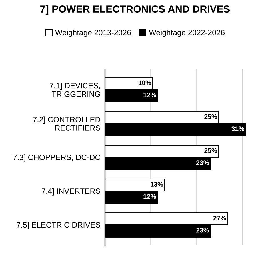
7.1] Power semiconductor devices and triggering
32 questions
The thyristor in the circuit shown below is turned on at , when key is switched off. Determine the conduction time of and the capacitor voltage after is turned off. Given that the inductor carries an initial current of 250 A and initial capacitor voltage is zero:
[Figure: DC source (+ at top) on the left between the bottom rail and node A. Between node A and node B: inductor , and in parallel with it a 250 A current source (arrow pointing left, i.e. from B towards A) in series with key (“Open at ”). From node B: thyristor (anode at B, cathode towards the right, gate shown) to the top of capacitor , whose lower plate returns to the bottom rail; capacitor voltage marked + at top, − at bottom] [2026/10m/5c]
A diode circuit with an – load is shown in the figure, with the capacitor having an initial voltage , capacitance and inductance . If switch is closed at , then find the following: (i) Peak value of current (ii) Conduction time of the diode.
[Figure: Single loop: capacitor (with , + on its upper plate) in series with inductor on the right-hand side; from the top of the current flows (arrow pointing left) through switch (closes at ) along the top; the left-hand side has a diode pointing downwards (anode at top, cathode at bottom); the bottom wire returns to the lower (−) plate of .] [2024/10m/5c]
The circuit given in the figure below is in steady state initially before the thyristor is triggered. The thyristor is triggered at . Calculate (i) the maximum current the thyristor will carry. (ii) the instant of carrying maximum current by the thyristor. (iii) the conduction time of the thyristor. (Assume zero latching and holding current for the thyristor)
[Figure: 200 V battery (positive at top) between the top node T and the bottom wire. From T: a thyristor (anode at T, cathode at node M, gate terminal shown) down to node M; in parallel with the thyristor, a 1.5 mF capacitor from T along the top wire in series with a 3.0 mH inductor down to node M. From M, 4 Ω down to the bottom wire (battery negative).] [2023/10m/7c]
(i) An SCR having a turn ON time of 5 μ sec, latching current of 50 mA and holding current of 40 mA is triggered by a short duration pulse and is used in the circuit shown in Figure 8(a)(i). Find the minimum pulse width required to turn the SCR ON.
[Figure: Figure 8(a)(i): 100 V dc source (+ at top); from its + terminal an SCR (anode on the source side, gate trigger shown) to the top node; from the top node to the bottom wire two parallel branches: (1) a 20 Ω resistor in series with a 0.5 H inductor, (2) a 5 kΩ resistor; the bottom wire returns to the − terminal of the source]
(ii) A 3-phase, delta-connected, 6-pole, 50 Hz, 400 V, 925 rpm, squirrel cage induction motor has the following parameters: , , , The motor is fed from a voltage source inverter with constant V/f ratio below 50 Hz and constant voltage of 400 V above 50 Hz frequency. Calculate: • Speed for the frequency of 35 Hz and half of full-load torque, • Frequency for a speed of 600 rpm and 80% of full-load torque and • Torque for a frequency of 35 Hz and speed of 650 rpm. Assume motor speed – torque curves to be parallel straight lines in the region of interest. [2020/20m/8a]
(i) Draw thyristor gate characteristics and state its application in design of gate drive circuit. (ii) A thyristor has a maximum average gate power dissipation limit of 0.4 watts. It is triggered with pulsed gate current of frequency 20 kHz at a duty ratio of 0.5. If the gate cathode voltage drop is 1 volt, find permissible peak gate current magnitude. [2018/10m/1c]
The SCR shown in Fig. 5(c) has a limit of . It is to be operated from a 100 V d.c. supply with load resistance . (i) What is the minimum value of load inductance that will protect the SCR? (ii) If an snubber is connected across the SCR with , what will be the new value of load inductance to protect the SCR against ?
[Figure: Fig. 5(c): d.c. supply (+ terminal at top, − at bottom); from the + terminal, inductor in series with to the anode of the SCR; SCR cathode returns to the − terminal; gate current shown entering the gate] [2016/10m/5c]
A single-phase converter feeds an – load having a resistance of 10 ohms in series with an inductance of 20 mH. The converter operates such that the d.c. voltage across the load is 250 V. The thyristor used in the converter has holding current of 300 mA and a delay time of 5 μs. Determine the pulse width of gate current. [2014/10m/5c]
What is the effect of gate capacitance of MOSFET in driving circuit when it is used in high-frequency power switching applications like sine wave inverter or DC–DC converter? [2013/10m/7c]
Distinguish between voltage-controlled power devices and current-controlled power devices with examples. [2009/6m/7b(i)]
What are the characteristic features of a GTO in relation to a thyristor? [2009/8m/7b(ii)]
Distinguish between the minimum current required to turn-on a thyristor and the minimum current to keep the thyristor in conduction. Explain with reference to the static characteristics of a thyristor. [2009/6m/7b(iii)]
What is the essential difference in commutation performance of triac and two thyristors connected in antiparallel? [2007/8m/2c(i)]
How is an SCR protected against high and ? Give circuit configuration and explain the role of each component. [2006/8m/2c(ii)]
What is a TRIAC? Explain its characteristic. Discuss its applications, advantages and disadvantages. [2005/15m/2c(i)]
A voltage across SCR is 1 V when it is conducting. It has a holding current of 2 mA when gate current . If the SCR is triggered on by momentary pulse of gate current to what value must be reduced in order to turn the SCR off? The figure is shown below.
[Figure: Input terminal connected through a 45 Ω resistor to the anode of an SCR whose cathode is connected to ground; a gate pulse is applied to the gate; is marked across the SCR (from the anode side to the grounded cathode).] [2005/5m/2c(ii)]
What are the steps involved for the generation of gating signals for thyristors of ac. to d.c. converters? Draw a block diagram incorporating various stages of firing circuits for a single-phase fully controlled rectifier. [2005/12m/3c(i)]
What are commutation circuits? Design a commutation circuit for an inverter. [2004/20m/2b]
In the circuit of the figure shown below, the source voltage E = 120 V and the current through loads and is 20 A. The turn-off time of both the SCRs is 60 μ sec. Find the value of C for successful commutation.
[Figure: Complementary (parallel capacitor) commutation circuit: battery E on the left; the top wire feeds two branches to the bottom wire: in series with (anode at the bottom of , cathode to the bottom wire) and in series with (same orientation); capacitor C connected between the anode of (− plate) and the anode of (+ plate).] [2004/10m/5c(i)]
Discuss why forward break over in a thyristor occurs at a lower anode-cathode voltage if its gate current is increased. [2003/5m/2b(i)]
What are the advantages of IGBT over BJT, MOSFET and thyristor? [2003/5m/2b(ii)]
Consider the circuit shown below. Main thyristor T1 and auxiliary thyristor TA are off and capacitor is charged to voltage with upper plate positive. Sketch the waveforms for , , , and (assuming constant load current), after (i) thyristor T1 is turned on (ii) steady state is reached in part (i) and then thyristor TA is turned on From these waveforms, obtain the expressions for circuit turn-off time for both SCRs. In case V, R = 10 Ω and maximum value of current through main SCR is 3 times the load current, calculate the value of commutating inductance L for C = 20 μF and the circuit turn-off time for the auxiliary SCR.
[Figure: d.c. supply (+ at the top input terminal, − at the bottom). From the top terminal (node P): main thyristor T1 (anode at P, gate G; voltage marked + at anode, − at cathode) to node K, current ; from K the load current flows through load resistor R to the bottom (return) wire. Capacitor C connected from node P (upper plate, +, voltage ) down to node M, with current . From M to K two parallel branches: auxiliary thyristor TA (anode at M, cathode at K) and a diode in series with inductor L (diode cathode towards M, i.e. conducting from K towards M through L).] [2003/20m/8c]
.
(i) Germanium and silicon are both semi-conducting materials and we have both diodes and triodes with germanium as well as silicon. However, in respect of controlled rectifiers, we have only silicon-controlled rectifiers but no germanium-controlled rectifiers. Explain why. [2002/10m/2c(i)]
(ii) Use the two transistor equivalent circuit of the SCR and show that when reverse biased the SCR cannot contact even if it is triggered. [2002/10m/2c(ii)]
.
(i) Explain the main advantage of power MOSFETs over SCRs [2002/5m/8c(i)]
(ii) A fully controlled bridge rectifier has a voltage of 200 V d.c applied to its input terminals as shown.
[Figure: Single-phase full bridge of four SCRs fed from a 200 V dc source (+ terminal on the top rail, − terminal on the bottom rail). Left leg: from the + rail (anode) to node A (cathode); from the − rail (anode) to node A (cathode). Right leg: from node B (anode) to the + rail (cathode); from node B (anode) to the − rail (cathode). LOAD between A and B: 20 Ω resistor in series with 1 H inductor.]
Identify the forwarded and reverse biased SCRs in the circuit. Assume the forward biased SCRs have a leakage resistance of 100 MΩ and the reverse biased SCRs have 200 MΩ. Show that each of the devices is blocking a voltage of approximately 100 V in the circuit, irrespective of whether it is forward biased or reverse biased [2002/15m/8c(ii)]
While the Thyristors is used in Power Electronic convertors it is being replaced by other devices recently. Mention any two of these devices and explain how they differ from the Thyristors. Name typical convertors in which the Thyristors are being replaced. [2001/20m/2c]
How are the Power Semiconductor devices specified? What do these specifications signify? [2001/20m/8c]
Select any three of the following statements, read them carefully and identify correct and incorrect ones. Justify your answer using not more than 200 words in each case: An SCR is derated when it handles pulsed anode current. [1999/20m/200w/1c]
Fig. 3(a) shows a circuit employing class-C commutation. The circuit is initially relaxed. Sketch the waveform for , , , and for one cycle for explaining the commutation process of both the thyristors.
[Figure: Fig. 3 (a): d.c. supply (+ at the top rail, − at the bottom rail); from the top rail to the anode of thyristor T1, from the top rail to the anode of thyristor T2; cathodes of T1 and T2 connected to the bottom rail; commutating capacitor C connected between the anodes of T1 and T2, with voltage marked − at the T1 side and + at the T2 side and current marked (arrow towards the capacitor from the T2 side); thyristor voltages and (+ at anode) and currents , (downwards) marked] [1999/20m/3a]
Explain the mechanism for the dissipation of stored energy in a SCR during its commutation process. [1999/15m/4c]
Discuss the volt-ampere characteristic of a Triac. Explain its usefulness in speed control applications. [1997/20m/4a]
Select any three of the following statements, read them carefully and identify the correct and incorrect ones. Justify your answer using not more than 200 words in each case. A vacuum tube oscillator has small power outputs high at frequencies and is less efficient compared to SCR. [1996/20m/200w/1d]
Fig. 2 shows a circuit used for self-commutation by resonance. (i) With the thyristor in blocking state, what is steady state capacitor voltage and load current? (ii) Derive an expression for the load current, thyristor current and after a thyristor is triggered at . (iii) Calculate the time when the thyristor would stop conducting.
[Figure: Fig. 2: Battery = 200 V (+ at top) between a top line and a bottom line. From the top line, capacitor C = 100 μF goes down to one end of inductor 0.1 H, whose other end joins node X; a thyristor is connected from the top line down to node X (in parallel with the series C–L branch); load resistor = 100 Ω from node X to the bottom line, carrying load current ; bottom line returns to the battery] [1996/20m/4c]
What are the important ratings that specify an SCR? Compare the performance characteristics of a rectifier circuit using ordinary diodes with that of one using SCR’s. [1995/20m/4a]
7.2] Phase-controlled rectifiers
30 questions
A single-phase, one-pulse, SCR-controlled converter with –– load has the following data: Supply voltage at 50 Hz, , , , firing angle and extinction angle 1. Calculate the voltage across the SCR at the instant SCR is triggered. 2. Find the voltage that appears across the SCR when current decays to zero. 3. Find the peak inverse voltage for the SCR. [2026/10m/7b(i)]
A single-phase Thyristor converter circuit as shown in the figure is feeding to a constant current load of 10 A. The supply voltage is of 230 V, 50 Hz and source inductance of 2 mH. Assume the Thyristors are ideal and triggering angle . Calculate (i) the overlap angle , and (ii) the drop in output voltage.
[Figure: Single-phase fully controlled thyristor bridge: two legs, each with an upper and a lower thyristor, all thyristors pointing upward (anode below, cathode above). AC source (+ at top) in series with source inductance (current ) connected to the midpoint of the left leg; the − terminal of connected to the midpoint of the right leg (wire crossing the left leg without connection). Top rail (cathodes of the upper thyristors) and bottom rail (anodes of the lower thyristors) feed a constant-current load of 10 A (current source with arrow pointing down, current flowing out of the top rail, arrow on top rail pointing right)] [2025/10m/5c]
A converter circuit as shown in the figure is being used to charge a battery of voltage . The average charging current , and supply voltage , 50 Hz. Determine (i) the value of limiting resistor ‘R’, and (ii) input power factor.
[Figure: Single-diode battery charger: ac source (~) on the left; from its upper terminal a diode (anode on the source side, pointing right) along the top wire, then resistor R in series with the battery (+ terminal towards R, i.e. at top) returning to the lower terminal of the source] [2025/20m/6b]
Draw the neat and properly labelled output voltage waveform of a three-phase, phase-controlled rectifier having firing angle . Also derive the relationship for average output voltage in terms of line voltage and firing angle . [2024/10m/7a(i)]
A three-phase full-wave controlled rectifier is being operated from a star-connected, 415 V, 50 Hz supply. This rectifier is feeding a constant current load of 15 kW. It is required to obtain an average output voltage of 80% of maximum possible output voltage. Find the firing angle, r.m.s. value of line current and input power factor. Assume devices are ideal. [2024/10m/7a(ii)]
A half-controlled converter fed from 240 V, 50 Hz single-phase ac source is feeding 1800 W power to a 100 V battery as shown in the figure below. The battery is connected in series with a large inductance and a resistance of 2 Ω. The inductance is large enough to make the load current flat and continuous. Find: (i) the triggering angle of the thyristors, (ii) rms value of fundamental component of converter input current, and (iii) the input power factor in the ac side. (Assume the inductor has a resistance of 1 Ω)
[Figure: Single-phase half-controlled bridge: two thyristors in the upper arms (anodes at the two ac input nodes, cathodes to the positive output rail) and two diodes in the lower arms (anodes on the negative output rail, cathodes at the ac input nodes); 240 V, 50 Hz supply connected between the two ac input nodes; a freewheeling diode across the output (anode on the negative rail, cathode on the positive rail); load: 2 Ω, L = Large and a battery 100 V, 1800 W in series between the output rails (from the positive rail: 2 Ω, then L, then the battery with its positive (longer) plate on the inductor side and its negative plate on the negative rail).] [2023/10m/5b]
A single phase AC bridge rectifier as shown in Figure 2(c) is operating at firing delay angle . The thyristor gets damaged and behaves as an open circuit. Calculate the value of load resistance R if load current is 3.1556 A.
[Figure: Figure 2(c): Single-phase full bridge of four thyristors, all pointing upward (anode at the bottom, cathode at the top). Left leg: (upper) and (lower); right leg: (upper) and (lower). The cathodes of and join the top rail; the anodes of and join the bottom rail. Load resistor R is connected between the top rail and the bottom rail on the right; load current flows to the right along the top rail. AC supply 200 V, 50 Hz: the upper supply terminal connects to the junction of and ; the lower supply terminal crosses the left leg (wire hop, no connection) and connects to the junction of and .] [2022/10m/2c]
A three-phase, full-wave thyristor bridge converter is operated from a three-phase, Y-connected 220 V, 50 Hz supply and the load resistance is 20 Ω. It is required to obtain an average output voltage of 50% of the maximum possible output voltage. Determine the following: (i) The delay angle (ii) The rms and average output currents (iii) The rms and average thyristor currents (iv) The rectification efficiency (v) The input PF. [2021/20m/7b]
Determine ripple factor of output voltage (), rectifier efficiency (η) and transformer utilization factor (TUF) for a single-phase half-wave controlled rectifier circuit fed from a source to a load R = 10 Ω. Assume firing angle α = π/4 and transformer to be lossless.
[Figure: Figure 5(e): AC source across the primary of a 220/12 V Transformer; the secondary feeds, through a thyristor (anode on the transformer side, firing angle α = π/4), the load R = 10 Ω; output voltage across R (+ at top, − at bottom)] [2019/10m/5e]
Draw output voltage and current waveforms and determine r.m.s. output voltage of a three-phase half-wave rectifier supplied by three-phase balanced a.c. supply. Also determine the form factor. If the supply voltage of the above converter is 220 V (r.m.s.) at 50 Hz and the load is of 1 kW at 200 V, purely resistive, determine power consumed by the load with given supply voltage. [2018/10m/5c]
A three-phase uncontrolled diode rectifier supplies a constant load current of 10 A and its supply voltage is 400 V line-to-line. Determine the following performance measures: (i) Average output voltage (ii) Supply r.m.s. current (iii) Supply fundamental r.m.s. current (iv) Supply 3rd, 5th, 7th and 9th harmonic r.m.s. current (v) Supply current displacement factor (vi) Supply power factor (vii) AC power (supply power) (viii) DC power (load power) [2017/20m/3b]
A single-phase full converter is connected to RLE load. The source voltage is 230 V, 50 Hz. The average load current of 10 A is constant over the working range. For R = 0.4 Ω and L = 2 mH, compute: (a) firing angle delay for E = 120 V and input power factor. (b) firing angle delay for E = −120 V and input power factor. [2015/20m/2b]
A single-phase full converter is supplied from 230 V, 50 Hz source as shown in Figure. The load consists of R = 10 Ω and a large inductance so as to render the load current constant. For firing delay angle of 30°, determine: (a) average output voltage (b) average output current (c) average and rms values of thyristor current (d) input power factor.
[Figure: Single-phase fully controlled thyristor bridge: source connected between the midpoints of the two legs; left leg (upper) and (lower), right leg (upper) and (lower); cathodes of and joined to the top (positive) rail, anodes of and joined to the bottom rail; load R in series with L connected between the top and bottom rails] [2015/10m/5a]
A battery is charged through a resistor R as shown in Fig. For an ac source voltage of 230 V, 50 Hz find the value of average charging current for R = 8 Ω and E = 150 V.
[Figure: Single loop: a.c. source ; from its upper terminal a thyristor (drawn with gate; anode towards the source, cathode towards R) in series with resistor R to the + terminal of battery E; the − terminal of the battery returns to the lower terminal of the source] [2015/10m/5b]
A single-phase fully controlled bridge converter supplies an inductive load. Assuming that the output current is virtually constant and is equal to 20 A, determine the following performance measures, if the supply voltage is 230 V and the firing angle is maintained at 30°: (i) Average output voltage (ii) Supply r.m.s. current (iii) Supply fundamental r.m.s. current (iv) Fundamental power factor (v) Supply power factor (vi) Supply harmonic factor (vii) Voltage ripple factor (viii) Reactive power input. [2014/10m/5a]
A 11 kV dc source having internal resistance of 1 ohm supplies 600 A to a 5 kV, 3 phase, 6-pulse 50 Hz inverter. Compute the: (i) reactive power absorbed by the inverter, (ii) effective value of the ac line current, (iii) the required firing angle, (iv) dc voltage generated by the inverter, and (v) dc current carried by each SCR. [2012/20m/8b]
Draw circuit diagram for the following: (i) Three-phase FW bridge rectifier (ii) Boost switching regulator (iii) DC trigger circuit for an SCR. [2011/15m/5c]
A d.c. battery having a constant e.m.f. is charged through a 1-phase full converter. A resistor limits the battery charging current. Single-phase source voltage is . Sketch waveforms for source voltage, output voltage and charging current. Derive an expression for the average charging current on the assumption that each pair of thyristors is fired continuously in each half-cycle. Take as the voltage drop in each conducting pair. [2010/16m/2c(i)]
In part (i) above, find the value of in case battery charging current is 5 A, supply voltage is 40 V, 50 Hz; and . [2010/4m/2c(ii)]
With a neat circuit diagram, explain the operation of a 180° variable half-wave rectifier along with its gate trigger circuit. [2009/15m/5c]
A battery is charged through a resistor R as shown: If E is 220 V (rms), V (dc) and R = 20 Ω, calculate the battery charging current and power supplied to the battery.
[Figure: Single loop: a.c. source ; from its upper terminal a thyristor (anode towards the source, cathode towards R, gate lead at the cathode end) in series with resistor R to the + terminal (longer plate, upper) of battery ; the − terminal of the battery returns along the bottom wire to the lower terminal of the source] [2007/12m/2c(ii)]
What are the advantages of half-controlled converters over fully-controlled converters? Show the output voltage waveforms for controlled and uncontrolled halves of the converter and the resultant voltage. [2007/10m/3c(i)]
A battery is charged by a single–phase half–wave controlled rectifier using SCR circuit. A resistance of 10 ohms is used between rectifier and battery. An ac source voltage of 230 V, 50 Hz is used as input to rectifier. If the battery voltage is 150 V dc, find (1) average charging current (2) power supplied to battery. [2006/12m/2c(i)]
A fully controlled three-phase bridge is operating in inverting mode from an ac supply of 220 V, 50 Hz. The source inductance per phase is 0.32 mH. If the converter is operating with an angle of firing advance of 30°, calculate maximum current that can be commuted, allowing a recovery angle of 5°. Neglect device volt drops. [2006/6m/5c(iii)]
If the SCR in the following figure is continuously fired by a d.c. signal, what is average value of the current i(t)?
[Figure: Single series loop: a.c. source on the left, an SCR (anode on the left) in the top wire, a 12 Ω resistor carrying i(t) (arrow to the right), and a 165 V battery on the right side with its positive (long) plate at the top, i.e. opposing the forward current of the SCR.] [2005/8m/3c(ii)]
A three-phase full-converter feeds a resistive load of 15 Ω. For a firing-angle delay of 75°, the load takes 6 kW. Find the magnitude of per phase input supply voltage to the three-phase full-converter. Derive the relevant expression used if any. [2003/20m/2c]
For the, circuit shown above, thyristor T is turned on at a triggering angle greater than that given by . Draw waveforms for , and . Derive an expression for the average charging current . For supply voltage of 30 V, 50 Hz and constant battery e.m.f. of 6 V find the resistance to be inserted in series with the battery to limit the average charging current to 3 A in case thyristor T is turned on at a firing angle of 20°.
[Figure (printed above the text): Battery-charging circuit: ac source in series with thyristor T (voltage marked across it, + on the anode side), resistor R and battery E, forming a single loop; charging current marked flowing from R towards the battery.] [2000/20m/3c]
For a single-phase one-pulse controlled converter system, sketch waveforms for load voltage and load current for (i) RL load and (ii) RL load with freewheeling diode across RL. Compare these waveforms and discuss the advantages of using a freewheeling diode. State the assumptions made. [2000/20m/5c]
Describe the working of a 3-phase full converter when connected to a resistive load. The firing angle is approximately 70°. Derive an expression for its average output voltage in terms of firing angle, input supply voltage. [1999/20m/3b]
Obtain (i) average load voltage and (ii) rms load voltage in case of 3 full wave rectifier. Hence calculate ripple factor. [1998/20m/4b]

Preparing for Prelims too?
Our UPSC Prelims Topic-wise PYQ eBook covers every Prelims question with detailed explanations, so you can see exactly where UPSC asks from.
View the BookDownload Free Sample7.3] Choppers and DC-DC converters
30 questions
For a type-A chopper feeding an –– load, show that the maximum value of average current rating for the freewheeling diode, in case the load current remains continuous, is given by where is the input voltage to the chopper. [2026/10m/7b(ii)]
The buck-boost converter has an input voltage of . The duty cycle and the switching frequency is 20 kHz. The inductance and filter capacitor . The average load current . Determine: (i) the peak-to-peak ripple in the inductor current, and (ii) the critical values of inductor L and capacitor C for CCM. [2025/10m/7c]
An ideal DC–DC converter as shown in the figure has an input voltage of , the duty ratio and the switching frequency is 20 kHz. The inductance and capacitance . The average diode current is 1.2 A. Determine the following: (i) Peak-peak ripple current of the inductor (ii) Peak current through the switch
[Figure: Buck-boost converter: switch from the + terminal of to node N; inductor from N to the bottom rail (− of ); diode between N and the output node with its cathode at N and anode at the output node; capacitor and the LOAD (output voltage , + at top) each from the output node to the bottom rail.] [2024/10m/8c]
Describe the performance requirements of a chopper circuit that can perform the chopping functions in any modulation technique. [2022/10m/4b(ii)]
Determine the value of inductance L, capacitance C and duty cycle of a buck regulator shown in Figure 6(b). The input voltage is 16 V, output voltage is 4 V, and ripple voltage (peak-to-peak) is 30 mV. The regulator is operating at 20 kHz switching frequency and peak-to-peak ripple current in inductance is 0.75 A.
[Figure: Figure 6(b): Input terminals + (top) and − (bottom) with . From the + terminal an inductor L in series along the top line to a node; from this node a thyristor-type switch (triangle pointing up, anode at the bottom line, cathode at the node, gate lead drawn at the cathode) goes down to the bottom line. From the node a diode (anode left, cathode right) in series along the top line to the output node. Capacitor C from the output node to the bottom line, and a block labelled LOAD from the output node to the bottom line; output voltage across the load , + at the top, − at the bottom.] [2022/20m/6b]
A step down dc chopper is feeding a load of and . The dc supply voltage is 100 V. The chopper is switching at a frequency of 2 kHz with a duty cycle of 50%. Determine the load current and the peak-to-peak ripple current as an absolute value and as percentage of dc value. [2021/10m/5a]
In Figure 2(a)(ii)(A), the ideal switch S is switched on and off with a switching frequency f = 10 kHz. The circuit is operated in steady state at the boundary of continuous and discontinuous conduction, so that the inductor current i is as shown in the Figure 2(a)(ii)(B). Find the values of on-time of the switch and peak current of inductor .
[Figure: Figure 2(a)(ii): (A) Circuit: 100 V dc source (+ at top); its + terminal connects through switch S to the top node; a 100 μH inductor from the top node to the bottom wire, with current i flowing downward; from the top node a diode (cathode at the top node, anode towards the right) to the − terminal (top) of a 500 V dc source whose + terminal is at the bottom wire; the 100 V source’s − terminal is on the bottom wire. (B) Waveforms against t: switch state S (high during , low during ) and below it the inductor current i, a triangular waveform rising linearly from zero to the peak during and falling linearly back to zero during , then immediately rising again] [2020/10m/2a(ii)]
(i) Figure 6(b) shows a step-up dc-dc converter with ideal devices and elements. In its steady-state analysis the output filter capacitor is assumed to be very large to ensure a constant output voltage . The switch is turned on and off periodically with a frequency of and duty ratio of D. With the help of neat waveforms, find the expressions for peak-to-peak current ripple of inductor (, peak) and output voltage ripple () at steady-state in terms of circuit parameters and variables.
[Figure: Figure 6(b): Boost converter: input voltage (+ at top); inductor L (voltage , + on the source side) from the + input terminal to the switch node; switch S from the switch node to the bottom (return) wire; Diode (anode at the switch node) from the switch node to the output node; capacitor C and load resistor R in parallel from the output node to the bottom wire; output voltage across R (+ at top)]
(ii) In a step-up dc-dc converter shown in Figure 6(b), , , , , , and . Calculate peak-to-peak output voltage ripple () and the rms value of the ripple in diode current (which also flows through the capacitor). [2020/20m/6b]
A Type-A chopper circuit shown in Figure 1(e) below supplies a motor load from a DC source. Determine the value of maximum average current of the switch SW for constant load current operation of motor.
[Figure: Figure 1(e): DC source (+ terminal at top); switch SW (IGBT symbol) from the + terminal to the load node; freewheeling diode D from the bottom (−) wire to the load node (cathode at the load node); DC Motor (shown dashed) connected from the load node to the bottom wire, represented by armature resistance and inductance in series with back emf (+ at top) to the bottom wire] [2019/10m/1e]
A buck converter (D.C.-D.C. converter) has LC filter in the output to reduce ripple in output voltage. For continuous conduction mode, draw the waveforms of output voltage, inductor current and capacitor current. If the converter is switched at frequency ‘f’, prove that minimum values of ‘L’ and ‘C’ for ripple in inductor current and ripple in output voltages are given by Assume any data missing. D is duty cycle of switch and is the average output voltage. [2018/20m/6a]
(i) Explain the operation of Boost converter with voltage and current waveforms across the Boost inductor. Assume continuous conduction. (ii) Derive its output voltage equation in terms of duty cycle and input voltage. [2017/10m/5c]
A class-A chopper circuit is supplied from a d.c. source voltage 100 V. The chopper supplies power to a series – load with and . The chopper switch is ON for 1 ms in an overall period of 3 ms. Calculate average load voltage, maximum and minimum value of load current and average load current. Assume continuous current operation of the chopper. [2016/20m/8b]
An RLE load is operating in chopper circuit from a 500 V dc source as shown in Figure. For R = 0, L = 0.064 and constant E, the duty cycle is 0.2. Find the chopping frequency to limit the amplitude of load current excursion to 10 A.
[Figure: d.c. supply (+ upper terminal, − lower terminal); a thyristor in the upper line from the + terminal (anode at the supply side) to the output node; a freewheeling diode from the lower line to the output node (cathode at the output node); load from the output node to the lower line: R, L and battery E (+ terminal towards L) in series; load current and output voltage across the diode/load marked] [2015/10m/7c]
Describe the voltage-commutated chopper controlling the speed of a d.c. series motor with relevant schematic diagram and associated voltage and current waveforms as a function of time. [2014/20m/7c]
Specify the type of core used in DC–DC converter and explain why iron core is not used in it. [2013/10m/5c]
Draw the simplified circuit diagram for a voltage step-up DC-converter and show that when duty cycle is zero, the output of DC-converter is equal to source voltage whereas DC voltage is infinity if the duty cycle is unity. [2012/12m/5d]
Draw circuit diagram for the following: (i) Three-phase FW bridge rectifier (ii) Boost switching regulator (iii) DC trigger circuit for an SCR. [2011/15m/5c]
Write voltage equations governing the performance of type-A chopper during on-period and off-period for the RLE type load. Hence, obtain therefrom, using Laplace transform, the expressions for the maximum and minimum currents taken by the load. Assume continuous conduction. [2010/20m/6c]
How are choppers classified, based on direction of current and voltage? Indicate with – diagrams. [2009/8m/4b(i)]
For a step-down chopper, derive an expression for peak-to-peak ripple current in terms of supply voltage , output voltage , frequency of operation and inductance. [2009/12m/4b(ii)]
An ideal chopper operating with a chopping period of 2 m sec is supplying a load of 5 Ω resistance with inductance of 10 mHenry, from a battery of 100 volts. Assume the shunt diode to provide perfect commutation. Determine the load current waveform for the ratio and average value of load voltage. [2007/20m/8c]
Draw the circuit diagram of a step–up/step–down dc chopper. Write expression for the average output voltage using energy balance equation. [2006/10m/3c(i)]
A chopper circuit is operating on Time Ratio Control strategy at a frequency of 2 kHz on 220 V dc supply. If the load voltage is 200 V dc, compute the conduction and blocking period of SCR in each cycle. [2006/10m/3c(ii)]
Explain briefly the different control strategies of chopper. [2006/4m/8c(i)]
An ideal single quadrant chopper operating in first quadrant is supplied with power from an ideal battery source of terminal voltage 200 V. The load voltage waveform consists of rectangular pulses of duration 1 [?] msec in overall chopper time of 3 msec. Calculate the average and rms values of the load voltage and voltage ripple factor. [2006/6m/8c(ii)]
A 230 V D.c. source feeds a separately-excited d.c. motor through a chopper operating at 400 Hz. The load torque at 1200 r.p.m. is 32.5 Nm. The motor has , mH and V-s/rad. All motor and chopper losses are neglected. Calculate (i) the armature current excursion and (ii) the armature current expressions during on and off periods. [2000/20m/2b]
Select any three of the following statements, read them carefully and identify the correct and the incorrect ones. Justify your answer using not more than 200 words in each case. Commutation has to be specially taken care of, While using Thyristor-Chopper for motor speed control. [1997/20m/200w/1d]
The above figure shows a chopper circuit operating at 100 Hz with a . The load current at steady state is continuous but varies between 3 amps and 10 amps. Sketch the wave shape of (i) the load current, (ii) the current through the free wheeling diode (iii) the current through the commutating capacitor.
[Figure: Thyristor chopper (sketch, partly unclear): main thyristor from the supply line to the load node; a commutating circuit consisting of diode , capacitor C in series with inductor L (current , double-headed arrow) and diode , with an auxiliary thyristor ; the load (resistor and inductor in series, current downwards) connected from the load node to the return line; free-wheeling diode across the load (current upwards)] [1997/20m/4b]
Describe with a neat sketch a step up chopper and discuss its merits and demerits. [1996/20m/4a]
A chopper circuit as shown in Fig 2 is inserted between a battery, V and a load resistance . The turn-off time for the main thyristor is 110 μs and the maximum permissible current through it is 30A. Calculate the values of the commutating components L and C.
[Figure: Fig. 2: Battery (+ at top) between a top line and a bottom line. Main thyristor in the top line (anode towards the battery, cathode towards the load) feeding node X; load current flows from X through load resistor to the bottom line and back to the battery. Commutation circuit: capacitor C from the anode side of (top line) down to node Y (C marked − at the top plate and + at the bottom plate); auxiliary thyristor from Y (anode) to X (cathode); inductor L in series with diode D also between Y and X, the diode’s anode towards X and cathode towards L, so that it conducts from X through D and L to Y] [1995/20m/4b]
7.4] Inverters
14 questions
Discuss in brief various methods of voltage control within 3-phase inverters. [2025/10m/8c]
Explain why PWM inverters are preferred over square wave inverters. Further, draw the harmonic spectrum to highlight the differences in unipolar and bipolar PWM techniques. [2024/10m/6b(i)]
A single-phase, full-bridge inverter has DC-link voltage , and the fundamental frequency of 50 Hz. Find the r.m.s. value of the voltages of the fundamental and next two prominent harmonics for the following cases: (1) Square wave mode (2) Voltage cancellation mode with [2024/10m/6b(ii)]
A three-phase bridge inverter shown in Figure 6(b) is used to feed a Y-connected resistive load with per phase. The dc input to the inverter and the output frequency is 50 Hz. If the inverter is operating with 180° conduction mode, (i) compute the rms value of the load current, (ii) compute the rms value of the current in each switching device, (iii) calculate the output power, and (iv) draw the waveforms of phase and line voltages.
[Figure: Figure 6(b): Three-phase bridge inverter fed from dc source (+ at the top rail). Three legs between the top and bottom rails, each with two transistor switches (IGBT symbols) and anti-parallel diodes: leg a – / (upper), / (lower), midpoint a; leg b – / (upper), / (lower), midpoint b; leg c – / (upper), / (lower), midpoint c. Y-connected load: a resistor R from each of a, b and c to the common star point n.] [2021/20m/6b]
For a series inverter shown below, the time interval between the instant Thyristor is turned OFF and the instant Thyristor is turned ON is seconds; where (minimum turn-off time of Thyristor ). Draw steady state waveforms of , (gate currents of Thyristor and respectively), capacitor voltage , inductor voltage , load current and supply current . Analyse and identify in waveform drawn, different modes of circuit operations; namely Mode-1, Mode-2 and Mode-3. Analysis may be accompanied by relevant equations and their derivation.
[Figure: Figure 3(a): Series inverter: dc source (+ at top); thyristor (gate current ) from the + terminal of to a node, supply current flowing to the right; thyristor (gate current ) from that node to the bottom (return) wire, anode at the node; from the node, capacitor C (voltage , + on the left) and inductor L (voltage , + on the left) in series, then the load resistor R (voltage , + at top, load current flowing downward) to the bottom wire] [2019/20m/3a]
A full bridge or H-bridge inverter has a switching sequence which results in a square wave output voltage. Let the switching frequency be 50 Hz and inverter is supplying a RL load having and . Determine: (i) An expression for load current (ii) The power absorbed by load (iii) The average current in the D.C. source (iv) The area in output voltage waveform where antiparallel diodes across switches conduct (Assume Input D.C. voltage = 100 V) [2018/20m/3b]
A single-phase full-bridge square-wave inverter is supplying power to a purely resistive load of 20 Ω. The d.c. source voltage is 600 V. If the inverter is to operate at 500 Hz with an r.m.s. load voltage 500 V, find— (i) average power absorbed by the load; (ii) average source current (assume no losses in switching); (iii) average current of each switch. [2016/10m/7d]
Give the circuit of a single-phase half-bridge inverter. Draw the load current waveform for a highly inductive load. Explain the purpose of the feedback diodes. [2009/10m/2c(ii)]
What are commutation circuits? Design a commutation circuit for an inverter. [2004/20m/2b]
A 12-V battery feeds a single-phase full-bridge inverter whose output is connected to an ideal 1-phase transformer. Its primary has 10 turns and the load voltage is 230 V. For a load resistance of 100 Ω, calculate (i) the number of turns in the transformer secondary winding, (ii) rms value of primary current, and (iii) rms value of thyristor current. Consider only the fundamental component of inverter output voltage. [2003/20m/3c]
Explain the principle of pulse with modulated inverters for induction motor control. What is the purpose of using pulse width modulation in this context? [2002/20m/3c]
A single-phase full bridge inverter feeds a load that allows load commutation. Explain how load commutation is achieved. Describe the conduction of various elements of the inverter circuit. [2000/20m/8c]
Discuss the principle of working of a 3-phase bridge inverter with an appropriate circuit. Draw phase and line voltage waveforms on the assumption that each thyristor conducts for 180° and the resistive load is star connected. Indicate the sequence of firing for thyristors as well. [1999/25m/4b]
The load connected at the output of a single phase bridge inverter is a series combination of R = 10 Ω and L = 0.05H. Determine the load voltage and current waveforms for the first two half cycles with rectangular wave output at 50 Hz. The input of the inverter is V. Also find the expression for the steady state current in each half cycle. [1997/20m/4c]
7.5] Electric drives
34 questions
A 240 V, 1200 r.p.m., 15 A, separately excited DC motor has armature resistance of . The motor is operated under dynamic braking with chopper control. The braking resistance has a value of . 1. Calculate the duty ratio of the chopper for the motor speed of 1000 r.p.m. and braking torque equal to 1.5 times the rated motor torque. 2. What will be the motor speed for the duty ratio of 0.5 and motor torque equal to its rated torque? [2026/10m/8b(i)]
A 200 V, 875 r.p.m., 150 A, separately excited DC motor has an armature resistance of . It is fed from a single-phase fully controlled rectifier with an AC source voltage of 230 V, 50 Hz. Assuming the continuous conduction, calculate the— 1. firing angle () for rated motor torque and 750 r.p.m.; 2. firing angle for rated motor torque and (–500) r.p.m.; 3. motor speed for and rated torque. [2026/10m/8b(ii)]
A 120 V, 1000 rpm, 350 W separately excited dc motor is supplied via half-controlled single-phase bridge rectifier for speed control purpose. The supply voltage to the rectifier is 200 V, 50 Hz ac and to obtain the desired speed, the triggering angle is set at 105° at one instant. The armature current is discontinuous with an average value of 2 A and it continues up to 30° beyond voltage zero. The motor armature resistance is 1.5 Ω. Determine the operating speed of the motor. (Assume constant flux operation and no armature reaction) [2023/10m/6c]
A 415 V, 4-pole, 3-phase, 50 Hz, star-connected squirrel cage induction motor has per phase parameters of , , , and , all at rated frequency. The motor has a rated slip of 4%. Its speed is to be controlled by VVVF method using a VSI (Voltage Source Inverter). Find the voltage to be applied to the motor at 5 Hz operating frequency to maintain same peak torque as in 50 Hz. Also determine the speed at which rated torque appears at this frequency. (Neglect core losses in the motor and all motor parameters referred from stator side) [2023/20m/8a]
A 240 V, 50 Hz single phase supply is connected to a full controlled converter to control the speed of a 10 kW, 220 V separately excited dc motor. The rated current of motor at full load is 25 A, armature resistance is 0.4 ohm and machine constant is 0.3 V/rpm. Calculate the speed of motor when converter is operating at an angle , assuming continuous armature current. [2022/10m/4b(i)]
A 220 V, 1500 rpm, 10 A separately excited dc motor has an armature resistance of 1 ohm. It is fed from a single phase fully-controlled bridge rectifier with an ac source voltage of 230 V, 50 Hz. Assuming continuous load current, determine the following: (i) Motor speed at the firing angle of 30° and torque of 5 Nm (ii) Developed torque at the firing angle of 45° and speed of 1000 rpm. [2021/10m/8c]
A separately excited dc motor is controlled by varying its armature voltage using a single-phase fully-controlled converter bridge as shown in Figure 5(a). The field current is kept constant at rated value. The motor has an armature resistance of 0.2 Ω, and the motor voltage constant is 2.5 V/(rad/sec). The motor is driving a mechanical load having a constant torque of 140 Nm.
[Figure: Figure 5(a): Single-phase fully-controlled bridge of four thyristors fed from a 250 V rms, 50 Hz ac source connected to the mid-points of the two thyristor legs; the dc output feeds the motor armature through in series; the field winding is separately excited from a dc source, φ = constant]
For the firing angle of the converter being 60° and assuming the armature current to be continuous and ripple free, (i) calculate the motor armature constant. (ii) evaluate the motor speed in rad/sec. (iii) calculate the rms value of the fundamental component of the input current to the bridge converter. [2020/10m/5a]
(i) An SCR having a turn ON time of 5 μ sec, latching current of 50 mA and holding current of 40 mA is triggered by a short duration pulse and is used in the circuit shown in Figure 8(a)(i). Find the minimum pulse width required to turn the SCR ON.
[Figure: Figure 8(a)(i): 100 V dc source (+ at top); from its + terminal an SCR (anode on the source side, gate trigger shown) to the top node; from the top node to the bottom wire two parallel branches: (1) a 20 Ω resistor in series with a 0.5 H inductor, (2) a 5 kΩ resistor; the bottom wire returns to the − terminal of the source]
(ii) A 3-phase, delta-connected, 6-pole, 50 Hz, 400 V, 925 rpm, squirrel cage induction motor has the following parameters: , , , The motor is fed from a voltage source inverter with constant V/f ratio below 50 Hz and constant voltage of 400 V above 50 Hz frequency. Calculate: • Speed for the frequency of 35 Hz and half of full-load torque, • Frequency for a speed of 600 rpm and 80% of full-load torque and • Torque for a frequency of 35 Hz and speed of 650 rpm. Assume motor speed – torque curves to be parallel straight lines in the region of interest. [2020/20m/8a]
A 220 volts, 1500 r.p.m., 50 A separately excited D.C. motor is fed from a three-phase fully controlled rectifier. The rectifier is supplied with a balanced three-phase source with phase voltage of 230 volts (r.m.s.) at 50 Hz. Motor is holding an overhauling load at 1200 r.p.m. at full load torque. Determine the firing angle of converter if armature resistance is assumed to be 0.2 Ω. [2018/10m/7c]
A 200 V, 875 r.p.m., 150 A, separately excited d.c. motor has an armature resistance of 0.06 Ω. The motor armature terminals are fed from a single-phase fully controlled bridge rectifier. The input a.c. supply to bridge rectifier is 240 V, 50 Hz. Assuming continuous and ripple-free armature current, determine the following: (i) Firing angle of SCRs for rated torque and 750 r.p.m. (ii) Firing angle for rated torque and −500 r.p.m. Assume that field winding of the motor is connected to a constant d.c. voltage source. [2016/20m/7b]
Draw the circuit for the speed control of a separately-excited dc motor from a single-phase source and explain it. [2015/10m/6c]
A separately excited dc motor, operating from a single-phase half controlled bridge (semi-converter) at a speed of 1440 rpm, has an input voltage of 330 sin 314 t and back emf 80 V. The SCRs are fired symmetrically at in every half cycle and the armature has a resistance of 4 Ω. Calculate the average armature current and the motor torque. [2015/10m/8c]
A d.c. shunt motor takes a current of 80 A on a 480 V supply and runs at 960 r.p.m. The armature resistance is 0.25 ohm and the field resistance is 120 ohms. A chopper is used to control the speed of the motor in the range of 400–750 r.p.m. having constant torque. The on-period of the chopper is 3 ms. The field is supplied directly from 480 V supply. Determine the range of frequencies of the chopper. [2014/20m/6a]
Describe the voltage-commutated chopper controlling the speed of a d.c. series motor with relevant schematic diagram and associated voltage and current waveforms as a function of time. [2014/20m/7c]
A three-phase, four-pole, 50 Hz induction motor has a chopper-controlled resistance in the rotor circuit for speed control. Load torque is . When the thyristor is ON, the torque is 30 N-m at a slip of average 0.03. If , compute the average torque and speed. The motor develops a torque of 80 percent of ON torque when the thyristor is OFF. The speed variation ranges down to 1200 r.p.m. from synchronous speed. Determine the ratio to give an average torque of 25 N-m. [2014/15m/8c]
Draw the circuit diagram of SCR-based control circuit for full-range speed control of a shunt DC motor using two SCRs to run from single-phase AC mains. [2013/20m/7b]
(i) Explain with diagram the soft starting of induction motor to start from zero speed to rated speed. Briefly compare with a star-delta starter used for the same purpose. (ii) A 3-phase, 4-pole 50 Hz induction motor is controlled by a variable frequency inverter that maintains the ratio of voltage to frequency across the motor constant. Torque-speed curve in stable region is a straight line. It has a maximum torque of 2 p.u. and slip speed at maximum torque at all frequency is constant at 150 rpm. Draw a family of Torque speed characteristics (on a graph paper) at 10, 20, 30, 40 & 50 Hz with usual assumptions. It is driving a load whose torque is directly proportional to speed giving rated torque at 50 Hz. Graphically calculate speeds at all the above frequencies. [2012/20m/7b]
Why are the frequency and voltage both varied in the same proportion for a full-range variable speed control of AC motor? [2011/20m/7c]
A d.c. series motor is powered by a d.c. chopper. The armature resistance is ohm and the field resistance ohm. The back e.m.f. constant of the motor is . The average armature current A. The armature current is continuous and has negligible ripple. If the duty cycle of the chopper is 75%, determine– 1. the input power from the source; 2. the equivalent input resistance of chopper drive; 3. the motor speed. [2009/10m/2c(i)]
The speed of a 20-hp, 220 V, 1000 rpm dc series motor is controlled by a single phase half-controlled full wave ideal converter Series field winding and armature winding have resistances 0.05 Ω and 0.12 Ω respectively. Input to converter is 230 V, 50 Hz supply. Calculate the motor torque, current and supply power factor at rated load and speed for firing delay angle . Assume motor current to be continuous and ripple free. Residual back emf constant is 0.08 V/ rad/sec and armature current, dependent back emf (or torque) constant is . [2007/10m/3c(ii)]
Draw and explain the speed, torque and power-time curves for a typical electrical traction drive. Differentiate clearly between dynamic and regenerative braking. [2007/10m/5c(i)]
A 3-phase, 400 V, six-pole, 50 Hz induction motor with parameters , (referred to stator) is under regenerative braking action. Calculate (i) the maximum overhauling torque that it can hold and the range of speed for safe operation and (ii) the speed at which it will hold the overhauling load with torque of 160 N-m. [2007/10m/5c(ii)]
A 200 V, 875 rpm, 150 A, separately excited dc motor has an armature resistance of 0.06 Ω. It is fed from a single phase fully controlled rectifier with an ac source voltage of 220 V, 50 Hz. Assuming continuous conduction, calculate (1) firing angle for rated motor torque and 750 rpm. (2) motor speed for and rated torque. [2006/10m/8c(iii)]
Describe single-phase d.c. drive considering a phase-controlled converter supplying a d.c. motor load. With the help of a circuit diagram, explain the operation of a single-phase full converter circuit feeding a separately excited motor. [2005/12m/8c(i)]
A d.c. drive runs at 900 r.p.m. on no load when fed at 200 V d.c. from a full converter. Calculate the triggering angle of the converter thyristors if the motor has to run at 600 r.p.m. on no load. Input to the converter is 230 V a.c. Neglect drop. [2005/8m/8c(ii)]
The speed of a 20 HP, 460 V, 1000 rpm separately excited d.c. motor is controlled by a single-phase full-wave bridge circuit as shown in the figure: The rated motor armature current is 35 A and the armature resistance is 0.15 Ω. The a.c. supply voltage is 480 V [?]. The motor back emf constant is V/rpm. The motor current is continuous and ripple free. For rectifier operation (d.c. machine running as a motor) and for a firing angle α = 60° and rate armature current, calculate (i) torque, (ii) speed and (iii) supply power factor.
[Figure: Single-phase fully controlled bridge: a.c. supply v between two input terminals, input current i; four thyristors SCR1 (top left), SCR2 (top right), SCR4 (bottom left), SCR3 (bottom right), with SCR1 and SCR2 cathodes on the top (positive) d.c. rail and SCR4 and SCR3 anodes on the bottom d.c. rail; one supply terminal goes to the junction SCR1–SCR4, the other to the junction SCR2–SCR3; output voltage across the d.c. rails; load: armature current through , and the motor armature (back emf , + at top) in series between the rails; separately excited field winding shown beside the motor.] [2004/20m/3c]
A 6 MW, 3-phase, 11 kV, Y-connected, 6-pole, 50 Hz, 0.9 (leading) power factor synchronous motor has and . Rated field current is 50 amperes. Machine is controlled by variable frequency control at constant (V/f) ratio up to the base speed and at constant V above base speed. Determine the torque and field current for the rated armature current, 750 rpm and 0.8 leading power factor. [2004/20m/8c]
Two single-phase full converters are used for controlling the speed of a separately-excited dc motor. One full-converter in the field circuit has zero degree firing-angle delay. Both the converters are connected to 1-phase, 220 V, 50 Hz source. DC motor armature resistance is 0.6 Ω and field circuit resistance is 150 Ω and its constant is 0.6 V-s/A-rad. Armature and field currents are ripple free. For a firing angle delay of 40° and armature current of 40 A, determine.
(i) The motor speed in rpm, [2003/6m/5c(i)]
(ii) Power factor of the armature converter, and [2003/6m/5c(ii)]
(iii) Power factor of the drive scheme. [2003/6m/5c(iii)]
Explain the principle of pulse with modulated inverters for induction motor control. What is the purpose of using pulse width modulation in this context? [2002/20m/3c]
In an electric traction d.c. series motor has been used with single-phase a.c. overhead lines. Gradually it is being replaced by another motor along with suitable speed control mechanism. Explain this new system comprising the motor and its control from the same overhead supply system and compare with the one using d.c. series motor. [2001/20m/3c]
A fixed frequency chopper feeds a separately-excited dc motor supplied from 80 V dc source. The rated speed is 900 rpm and the rated armature current is 40 A. Armature circuit resistance is 0.25 Ω. Find the duty cycle of the chopper at half the rated motor torque for a speed of 300 rpm ignoring the current pulsations. [1999/20m/3c]
Discuss the electrical, mechanical and economic characteristics to be considered in selecting a motor for a given drive. What are the special features required for selecting electrical equipment for mines with fire hazard? [1996/20m/8b]
Select any three of the following statements, read them carefully and identify the correct and incorrect ones. Justify your answer using not more than 200 words in each case. Use of a free wheeling diode improves the quality of speed-torque characteristics of a thyristor controlled d.c. motor. [1995/20m/200w/1c]
Briefly explain the various controls in a.c. drives. Why are such drives becoming increasingly more popular as compared to d.c. drives? [1995/15m/7b]

Strengthen your GS papers
Our UPSC Mains Topic-wise & Year-wise PYQ eBook (2013–2026) maps every GS question to the syllabus, so you know what UPSC asks and how often.
View the BookDownload Free Sample« Previous: Energy Conversion | Next: Analog Communication »
Back to: Electrical Engineering Optional PYQs – Topic-wise
Last updated: 30 October 2026