
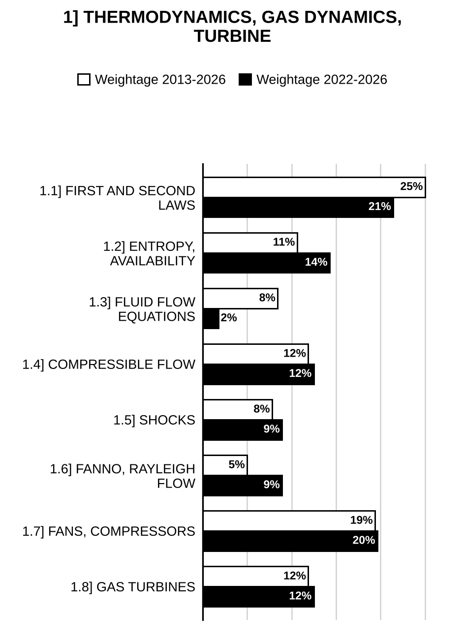
Here are all 262 Thermodynamics, Gas Dynamics and Turbine questions asked in UPSC Mechanical Engineering Optional Paper II from 1995 to 2026, arranged under the 8 topics of the official syllabus. Within each topic the latest questions come first.
Each question ends with a code such as [2024/15m/3b] – the year, the marks, the word limit (where UPSC set one) and the question number in the paper.
1.1] Laws of thermodynamics
58 questions
A piston-cylinder contains 2 kg of argon at and (state 1). Argon is heated by an electric heater of 10 A, 220 volts for 10 seconds at constant volume; during the process, 20% heat is lost (state 2). The gas is now allowed to expand from pressure to a final state with temperature and final pressure (state 3). The process 2–3 follows = constant. Find the index of expansion n for the process 2–3. Take for argon and . [2026/10m/1a]
A refrigeration system is to cool bread loaves with an average mass of 400 g from 25 °C to −10 °C at a rate of 400 loaves per hour by refrigerated air at −25 °C. Taking the average specific and latent heats of bread to be 2.90 kJ/kg-°C and 109.15 kJ/kg, respectively, determine (1) the rate of heat removal from the bread in kJ/hr and (2) the required volume flow rate of air in , if the temperature rise of air is not to exceed 5 °C. The gas constant of air is . The specific heat of air at average temperature is 1.0 kJ/kg-°C. Take atmospheric air pressure as 101.3 kPa. [2026/10m/2a(ii)]
A horizontal insulated cylinder has a frictionless and adiabatic piston held against stops by an external force of 500 kN, as shown in the figure below. The cross-sectional area of the piston is , and the initial volume is . Helium gas in the cylinder is at 200 kPa, 100 °C. A valve is now opened to a line through which helium is flowing at 1.2 MPa, 200 °C, and the helium flows in, until the cylinder pressure just balances the external force on the piston, at which point the valve is closed. Assume ambient at ; for helium, , and : Determine: (i) The final mass in the cylinder (in kg) (ii) The final temperature in the cylinder (in K) (iii) The total entropy generation (in kJ/K) (iv) The irreversibility (in kJ)
[Figure: Vertical supply line connected through a valve (circle with a cross) to the left end of a horizontal insulated cylinder containing “Helium”; a piston at the right end rests against stops, and an external force pushes the piston to the left.] [2026/20m/4b]
A reversible power cycle engine is used to drive a reversible heat pump. The power cycle takes in heat units at temperature and rejects heat at temperature . The heat pump abstracts heat from the sink at temperature and discharges heat at temperature . Develop an expression for the ratio in terms of the four temperatures , , and . [2025/10m/2a(i)]
A 2 gm quantity of air undergoes the following sequence of quasi-static processes in a piston-cylinder arrangement: (i) An adiabatic expansion in which the volume doubles. (ii) A constant pressure process in which the volume is reduced to its initial value. (iii) A constant volume compression back to the initial state. The air is initially at 150°C and 5 atm. Calculate net work on the air in the sequence of processes. [2024/10m/1a]
A 15 m high cylinder with a cross-sectional area of contains of liquid water at 25 °C on the top of a thin insulated piston of mass 20 kg. Below the piston, argon gas is at 15 °C with a volume of , as shown in the figure. Heat is supplied to argon such that the piston rises and pushes the water out over the top edge. Find the (i) work done (kJ) to remove the whole water from the top of the piston and (ii) heat transferred (kJ) to argon during the process. (iii) Plot the process on – diagram for argon. Assume atmospheric pressure () as 101 kPa, and for argon as 0.312 kJ/kg-K and 0.2081 kJ/kg-K respectively. The specific volume of water at 25 °C is . Neglect piston thickness:
[Figure: Vertical cylinder, open at the top to the atmosphere (pressure acting downwards on the water surface); a layer of “Water” rests on a thin piston, below which is “Argon”; gravity acts downwards] [2023/20m/2a]
A combination of a heat engine driving a heat pump (see the figure) takes waste energy at 50 °C as a source, , to the heat engine rejecting heat at 30 °C. The remainder, , goes into the heat pump that delivers at 150 °C. If the total waste energy is 5 MW, find the rate of energy delivered at the higher temperature. Assume heat engine and heat pump as reversible:
[Figure: Waste energy reservoir at 50 °C supplying to a heat engine (HE) and to a heat pump (HP); the HE rejects to a reservoir at 30 °C and delivers work to the HP; the HP delivers to a reservoir at 150 °C ()] [2023/20m/3b]
An evacuated 150 L tank is connected to a line flowing air (constant specific heat) at room temperature 25 °C and 8 MPa pressure. The valve is opened, allowing air to flow into the tank until the pressure inside is 6 MPa. At this point, the valve is closed. The filling process occurs rapidly and is essentially adiabatic. The tank is then placed in storage, where it eventually returns to room temperature. What is the final pressure inside the tank? [2023/10m/4c]
Consider the system shown in Fig. 1(a). The two chambers initially have equal volumes of 28 litres and contain air ( kJ/kg-K and kJ/kg-K) and hydrogen ( kJ/kg-K and kJ/kg-K), respectively. The chambers are separated by a frictionless piston which is non-heat-conducting. Both the gases are initially at 140 kPa and 40 °C. Heat is added to the air side until the pressure of both the gases reaches 280 kPa. All outside walls of the chambers are insulated except for the surface where heat is added to air. Calculate the final temperature of the air.
[Figure: Fig. 1(a) – A closed horizontal cylinder divided into two chambers by a piston: left chamber contains Air (shaded), right chamber contains ; the piston between them is labelled ‘Non-heat-conducting piston’; heat Q is supplied through the left end wall into the air; the remaining outer walls (top, bottom and right end) are hatched and labelled ‘Insulation’] [2022/10m/1a]
A water-filled reactor with a volume of is at 20 MPa and 360 °C, and is placed inside a containment room as shown in Fig. 5(b). The room is well-insulated and initially evacuated. Due to a failure, the reactor ruptures and the water fills the containment room. Find the minimum room volume so that the final pressure does not exceed 200 kPa. [Use steam table data given at the end of the Paper].
[Figure: Fig. 5(b) – A dome-shaped (semicircular) containment room with thick hatched walls, resting on a hatched floor (labelled Containment); a small rectangular box (labelled Reactor) stands on the floor at the centre inside the dome] [2022/10m/5b]
(i) 3 kg of air is compressed in a reversible steady flow polytropic process from 100 kPa, 40°C to 1000 kPa. During this process the law of compression followed is . Determine the shaft work, heat transferred and the change in entropy. Assume for air kJ/kg K and kJ/kg K. (ii) Distinguish between pdv work and –vdp work. [2021/20m/2a]
Air enters the compressor of a gas turbine plant at ambient conditions of 100 kPa and 25 °C with negligible velocity, and exits at 1 MPa and 347 °C with a velocity of 90 m/s. The compressor is cooled at a rate of 1500 kJ/min and the power input to the compressor is 250 kW. Determine the mass flow rate of air through the compressor. For air, consider , and . [2020/10m/1a]
A reversible engine works between three thermal reservoirs A, B and C. The engine absorbs an equal amount of heat from the thermal reservoirs A and B kept at temperatures and respectively, and rejects heat to the thermal reservoir C kept at temperature . The efficiency of the engine is times the efficiency of the reversible engine, which works between the two reservoirs A and C. Prove that . [2020/10m/1d]
A reversible heat engine operates between two thermal reservoirs of 1000 °C and 40 °C. The engine drives a reversible refrigerator operating between 40 °C and –10 °C. The amount of heat transfer to the engine is 4000 kJ and a net amount of work output of 1000 kJ is obtained from the combined engine-refrigerator system. Determine (1) the amount of heat transfer to the refrigerator and (2) the net amount of heat transfer to 40 °C reservoir. [2020/15m/3b(ii)]
A frictionless piston/cylinder is loaded with a linear spring (as shown in the figure below) having a spring constant of 100 kN/m, and the piston cross-sectional area is 0.1 m. The cylinder having an initial volume of 20 L contains air at 200 kPa and ambient temperature 300 K. There exists a stop in the cylinder which prevents its volume from exceeding 50 L. A valve connects the cylinder to an air supply line flowing air at 800 kPa, 325 K. The valve is now opened, allowing air to flow in until the cylinder pressure and temperature reach 800 kPa and 350 K respectively. The valve is then closed and the process ends. At the final state does the piston reach the stop? Calculate the heat transfer during the process. Take and for air:
[Figure: Vertical cylinder containing air below a hatched piston; a linear spring above the piston is compressed between the piston and a frame fixed to the cylinder top; two small stops project from the cylinder walls above the piston; at the bottom a valve (⊗) connects the cylinder to a horizontal air supply line, with an arrow marked i showing flow into the cylinder] [2020/20m/4a]
Water is pumped from the basement tank of a multistorey building to the terrace tank by a 20 kW motor. The free surface of the terrace tank is 45 m higher than the basement tank. If the flow rate of water is 0.03 m/s, determine the mechanical power that is converted to thermal energy during the process due to friction effect. Write the assumptions made in the calculation. [2019/10m/1a]
A 40 litres electrical radiator (heater) containing heating oil is placed in a 50 m room. Both the room and the oil in the radiator are initially at 10 °C. The radiator with a rating of 2.4 kW is now turned on. At the same time, heat is lost from the room at an average rate of 0.35 kJ/s. After some time, the average temperature for air in the room is 20 °C and the oil in the radiator is 50 °C. Take the density and the specific heat of the oil to be 950 kg/m and 2.2 kJ/kg-K respectively. Determine how long the heater is kept on. Assume the room is well-sealed and ambient pressure is 1 bar. [2019/10m/2a(i)]
Why are the temperature and pressure dependent properties in the saturated mixture region of pure substance? What is the difference between critical point and triple point? [2019/10m/2a(ii)]
A Carnot refrigeration cycle is operating between the minimum and maximum temperatures of –8 °C and 20 °C respectively. The refrigerant used in the cycle is R-134a and the cycle is operating in the saturated liquid-vapour region. The mass of the refrigerant is 0.8 kg and the refrigerant is saturated liquid at the end of heat rejection process. The net work input to the cycle is 15 kJ. Determine the fraction of the mass of the refrigerant that vaporizes during the heat addition process. Given at –8 °C = 204.59 kJ/kg at 20 °C = 180.33 kJ/kg. [2019/10m/3c]
The lighting needs of a classroom are met by 30 fluorescent lamps, each consuming 80 W of electricity. The lights in the classroom are kept on for 12 hours a day and 250 days during a year. For a unit electricity cost of ₹ 7 per kWh, determine the annual energy cost of lighting for this classroom. [2018/10m/1a]
A heat pump is to be used to heat a house during the winter as shown in Fig. 1. The house is to be maintained at 21 °C at all times. The house is estimated to be losing heat at a rate of 135000 kJ/hr when the outside temperature drops to −5 °C. Determine the maximum power required to drive this heat pump:
[Figure: Fig. 1 – Schematic: a house () losing heat at 135000 kJ/hr (“Heat loss” arrow from the roof); below it the heat pump (HP, circle) delivers upward to the house, receives from the cold outside air () below, and takes work input from the right.] [2018/10m/1c]
A rigid tank contains 10 kg of water at 90 °C. If 8 kg of water is in the liquid form and the rest is in the vapour form, determine (i) the pressure in the tank and (ii) the volume of the tank. Use the relevant data from the saturated water properties (Table 1) provided below for the calculations:
Table 1: Saturated Water Properties (specific volume in m³/kg; internal energy in kJ/kg; enthalpy in kJ/kg; entropy in kJ/kg-K)
| Temp., T (°C) | Sat. press., (kPa) | Sat. liquid, | Sat. vapour, | Sat. liquid, | Evap., | Sat. vapour, | Sat. liquid, | Evap., | Sat. vapour, | Sat. liquid, | Evap., | Sat. vapour, |
| 75 | 38.597 | 0.001026 | 4.1291 | 313.99 | 2161.3 | 2475.3 | 314.03 | 2320.6 | 2634.6 | 1.0158 | 6.6655 | 7.6812 |
| 80 | 47.416 | 0.001029 | 3.4053 | 334.97 | 2146.6 | 2481.6 | 335.02 | 2308.0 | 2643.0 | 1.0756 | 6.5355 | 7.6111 |
| 85 | 57.868 | 0.001032 | 2.8261 | 355.96 | 2131.9 | 2487.8 | 356.02 | 2295.3 | 2651.4 | 1.1346 | 6.4089 | 7.5435 |
| 90 | 70.183 | 0.001036 | 2.3593 | 376.97 | 2117.0 | 2494.0 | 377.04 | 2282.5 | 2659.6 | 1.1929 | 6.2853 | 7.4782 |
| 95 | 84.609 | 0.001040 | 1.9808 | 398.00 | 2102.0 | 2500.1 | 398.09 | 2269.6 | 2667.6 | 1.2504 | 6.1647 | 7.4151 |
| 100 | 101.42 | 0.001043 | 1.6720 | 419.06 | 2087.0 | 2506.0 | 419.17 | 2256.4 | 2675.6 | 1.3072 | 6.0470 | 7.3542 |
[2018/20m/2a]
An insulated rigid tank is divided into two equal parts by a partition. Initially, one part contains 4 kg of an ideal gas at 800 kPa and 50°C, while the other part is evacuated. The partition is now removed and the gas expands into the entire tank. Determine the final temperature and pressure in the tank. [2017/10m/1a]
The pressure in an automobile tyre depends on the temperature of the air in the tyre. When the air temperature is 25°C, the pressure gauge reads 210 kPa. If the volume of the tyre is 0.025 m³, determine the pressure rise in the tyre when the air temperature in the tyre rises to 50°C. Also, determine the amount of air that must be bled off to restore pressure to its original value at this temperature. Assume the atmospheric pressure is 100 kPa and gas constant of air, R = 0.287 kPa m³/kg-K. [2017/10m/3c]
Which is the more effective way to increase the efficiency of a Carnot engine–to increase keeping constant or to decrease keeping constant? [2016/10m/1a]
In a Carnot cycle, heat is received at 480 °C and rejected at 40 °C. The entropy of the sink increases by 0.0785 kJ/kg K per cycle. Determine the work done per cycle. [2014/10m/1a]
A reciprocating air compressor is used to fill rapidly a tank at 30 °C and 1 bar. The filling process is governed by The effects of kinetic energy are negligible. The ratio of the final to initial mass of air in the tank is 4. Work out the following: (i) Draw the system and show the control volume. (ii) List the assumptions made. (iii) What would be the work input to the compressor, if mechanical efficiency is 90%? [2014/20m/2a]
A certain amount of gas is filled in a tank X until its pressure is 100 kPa and temperature is 330 K. In another tank Y, 5 times the weight of gas in X is filled raising the pressure to 500 kPa and temperature 900 K. Both the tanks X and Y are now connected through a tube having a valve which is closed. Assuming the gas is ideal and if the valve is opened till equilibrium state is achieved, find the ratio of the volumes of both tanks, equilibrium temperature and pressure. The tanks are insulated. For the gas, take and . [2014/10m/3c]
It is thermodynamically advantageous to employ a heat pump rather than employing a direct electrical resistance heater for a room air heating application. Explain why. [2014/10m/5e]
Prove that the cyclic integral of ratio between heat transfer and temperature of any thermodynamic process is less than or equal to zero. [2013/20m/2a]
Hot gases enter the blades of a gas turbine with a velocity of 550 m/s and leave with a velocity of 120 m/s. There is an increase in the enthalpy of the gases in the blade passages to the extent of 5.1 kJ/kg. The rate of gas flow is 98 kg/min. Determine the power produced. [2013/15m/2c]
Explain Kelvin-Planck and Clausius statements of the second law of thermodynamics and prove that both the statements are equivalent. [2013/10m/5a]
In the event of failure of heaters in a spacecraft, heat is lost by radiation at the rate of 100 kJ/hr while electronic instruments generate 75 kJ/hr inside the spacecraft. Initially the air inside the spacecraft is at 1 bar, 25°C with a volume of 10 . How long it will take to reach air temperature of 0°C? [2012/12m/5d]
A small expander (turbine with heat transfer) has 0.05 kg/s helium entering at 1000 kPa, 300 K. The power output on shaft is measured at 55 kW. Find the rate of heat transfer neglecting kinetic energy. [2012/12m/5e]
It is desired to maintain a room at temperature of 20°C when outside temperature is 30°C. The volume of this room is 300 . The pressure in the room and outside is 1 bar. (i) The air in the room is renewed completely in 1 hour. Calculate the mass of air that the air conditioning system pumps into the room. (ii) Compute maximum possible C.O.P. of this A/C system. (iii) When this A/C system is switched-off, the temperature inside the room reaches 21°C in 20 minutes. Calculate the amount of heat transferred from the surroundings to the room. (iv) Calculate power required by this system. [2011/15m/1a]
(i) 0.5 of gas at 10 kPa and 130 °C expands adiabatically to 1 kPa. It is then isothermally compressed to its original volume. and . Represent these processes on P-V diagram. Find final temperature and pressure of gas. (ii) For compression work to be minimum, what should be process of compression? Is it used in practice? [2010/20m/1a]
A Carnot engine operates between source temperature of 500 K and sink temperature of 300 K. It produces work utilising the heat of 10 kJ from the source at 500 K. The work produced by this engine is utilised by a Carnot refrigerator operating between refrigerator temperature of 200 K and sink temperature of 300 K. Represent schematically these engine and refrigerator operations. Find out: (i) Work produced by the Carnot engine. (ii) Refrigerating effect produced at 200 K by the Carnot refrigerator. (iii) Total heat rejected to the sink at 300 K. (iv) By how much the refrigerator temperature be increased to get double the refrigerating effect as per (ii) above? (v) Total heat rejected to the sink at 300 K when the refrigerator operates as per the temperature for (iv) above. [2010/20m/2a]
Consider a Carnot cycle heat engine operating in the outer space. Heat can be rejected from this engine only by thermal radiation, which is proportional to the radiator area and the fourth power of the absolute temperature of the radiator (). Show that for a given engine work output and given temperature of the higher temperature reservoir (), the radiator area will be a minimum when the ratio . [2007/20m/200w/1a]
A fluid, contained in a horizontal cylinder fitted with a frictionless leak-proof piston, is continuously agitated by means of stirrer passing through the cylinder cover. The cylinder diameter is 0.40 m. During the stirring process lasting 10 minutes, the piston slowly moves out a distance of 0.485 m against the atmosphere. The net work done by the fluid during the process is 2 kJ. The speed of the electric motor driving the stirrer is 840 rpm. Determine the torque in the shaft and the power output of the motor. [2007/20m/200w/1b]
Using the concept of Second Law of Thermodynamics show that it is impossible to reach absolute zero temperature. [2005/20m/200w/1a]
A reversible heat engine operating between thermal reversible reservoir at 800°C and 30°C drives a reversible refrigerator which refrigerates a space at -15°C and delivers heat to a thermal reservoir at 30°C. The heat input to the heat engine is 1900 kJ and there is a net work output from the combined plant (heat engine and refrigerator) of 290 kJ. Determine the heat transfer to the 30°C thermal reservoir. [2005/30m/2a]
Give the Kelvin-Planck’s and Clausius’ statements of Second Law of Thermodynamics and show that violation of either statement implies violation of the other. A Carnot engine I operates between two reservoirs at temperatures of 2000 K and T K. Another Carnot engine II operates between the reservoirs at T K and 300 K. If both the engines have the same efficiency, determine the value of T. [2004/20m/1b]
A pressure vessel is connected, via a valve, to a gas main in which gas is maintained at a constant pressure and temperature of 1.4 and 85° C respectively. The pressure vessel is initially evacuated. The valve is opened and a mass of 2.7 kg of gas passes into the pressure vessel. The valve is closed and the pressure and temperature of the gas in the pressure vessel are then 700 and 60° C, respectively. Determine the heat transfer to or from the gas in the vessel. Determine the volume of gas before transfer. For the gas, take , . Neglect the velocity of the gas in the main. [2004/30m/2a]
A solar- powered refrigeration system is run by heat transfer from solar collector at temperature 400 K and rejects heat at 300 K. It receives heat from cold space at 200 K. Assuming the cycle to be reversible, and using law of thermodynamics and Clausius inequality, find the ratio . [2003/20m/200w/1a]
Two reversible heat engines A and B are arranged in series. Heat engine A rejects heat directly to B. Engine A receives 300 kJ of heat at a temperature of 427°C from a high temperature source while engine B rejects heat to a cold sink at 7°C. If the work output of A is two times that of B, find (i) intermediate temperature between A and B, (ii) efficiency of each engine, (iii) heat rejected by engine A and received by engine B and (iv) heat rejected to the sink. [2003/30m/2b]
A reversible heat engine absorbs heat energy from a stream of hot gases whose temperature is falling linearly from to . The engine rejects heat to a constant temperature sink at . Assuming that any reversible cycle can be considered to be equivalent to an infinite number of Carnot cycles, prove that the maximum efficiency attainable for this heat engine is [2002/20m/200w/1a]
A rigid insulated tank of 3 volume is divided into 2 compartments. One compartment of volume 1 contains an ideal gas at 0.1 MPa and 300 K while the second compartment of volume 2 contains the same gas at 1 MPa and 1000 K. If the partition between the two compartments is ruptured, calculate the final temperature and pressure of the gas. [2002/20m/200w/1b]
A mass of air initially at 760 KPa and 250°C occupies 0.026 . The air is expanded at constant pressure to 0.07 . A polytropic process with is then carried out followed by an isothermal process and the cycle is thus completed, Assuming all the processes to be reversible, (i) show all the processes on pV and Ts planes (ii) compute the heat received and rejected in the cycle (iii) calculate the efficiency of the cycle. [2002/30m/2a]
The ratio of heat transfer to work transfer in the process of an air compressor reciprocating type is 1/4, If the compression follows = constant, what is the value of n? Derive the equation that you use. In such a compression process the work required is 200 kJ/kg and the specific heat at constant volume is 0.75 kJ/kg K. What rise of temperature is expected at the end of compression process? [2001/20m/200w/1a]
A Carnot Engine is working between temperature limits of and . Its efficiency can be increased either by increasing the source temperature or by decreasing the sink temperature . Determine which is more effective. What are the practical limitations of each of the above methods? [2000/20m/200w/1d]
Show that violation of the Kelvin-Planck statement of the Second Law of Thermodynamics implies the violation of Clausius statement. [1999/10m/200w/1a(i)]
Figure shows a system that undergoes a reversible cycle during which it exchanges heat with three thermal reservoirs and develops 1000 kJ of work per minute. Find the heat interchange and .
[Figure: A cyclic device (circle) connected to three thermal reservoirs. Reservoir A at 1000 K (above) supplies 5000 kJ/min to the device (arrow from A down to the device). The device delivers work W = 1000 kJ/min (arrow to the right). The device is connected to reservoir B at 300 K (lower left), with the heat interaction marked / min, and to reservoir C at 500 K (lower right), with the heat interaction marked / min; the directions of and are not shown.] [1999/10m/200w/1a(ii)]
State Clausius inequality theorem and explain its significance. An inventor has claimed that he has developed an engine which receives 1000 kJ of heat at a temperature of 1000 K and rejects 200 kJ of heat at a temperature of 600 K, delivering the remaining input as work. Check whether the claim is possible using the above theorem. In case this engine has to be reversible, determine the amount of heat to be rejected. [1998/10m/200w/1a(i)]
In the winter season while outside is at 5 °C, a heat pump is used to maintain the living space at 20 °C. The heat gain into the space is 1.1 kJ/s per degree difference in temperature between inside and outside. Determine the power required to drive the heat pump. If during summer the same motor power is used to maintain the space at 20 °C, determine the maximum outside temperature upto which this will be possible. Heat loss rate can be assumed as in the winter season. [1998/20m/2b]
The efficiency of a reversible engine can be increased in two ways (i) increasing the source temperature maintaining the sink temperature constant, and (ii) reducing the sink temperature maintaining the source temperature constant. Show analytically that the second method will lead to larger improvement in efficiency for the same incremental change in temperature. [1998/20m/2c]
Air at 100 KPa and 300° C is contained in a piston cylinder arrangement as shown in fig.(1):
[Figure: Fig. 1. Horizontal cylinder closed at the left end containing Air, with a piston held in position; arrow “Q = 0” pointing to the cylinder wall (insulated); arrow P acting on the right face of the piston towards the air; two pairs of stops on the cylinder walls to the right of the piston, the nearer pair marked A and the farther pair marked B]
The cylinder is perfectly insulated and piston is held in position, by stops at A. The outside pressure is atm. The stops A are suddenly removed and the air allowed to expand till the piston stops at stops B. The volume increases to 1.5 times the initial value. Assume that the friction between piston and cylinder is zero. Calculate the final pressure and temperature of air. State your assumptions clearly. [1997/20m/200w/1b]
Show that when a gas expands behind a piston according to the law = constant, the heat transfer, change in internal energy and work done are in the ratio [?] and that the effective specific heat C for an expansion of this kind is [?] times its specific heat at constant volume . [1996/20m/200w/1b]
Discuss the essential differences in working principles of heat pump refrigerating machine and heat engine. Describe a summer air conditioning system with ventilation. [1996/20m/200w/5c]
1.2] Entropy, availability and irreversibility
50 questions
During a heat transfer process, the entropy change of incompressible substances, such as water, can be determined from . Show that for thermal energy reservoirs, such as large lakes, this relation reduces to . [2026/10m/2a(i)]
A horizontal insulated cylinder has a frictionless and adiabatic piston held against stops by an external force of 500 kN, as shown in the figure below. The cross-sectional area of the piston is , and the initial volume is . Helium gas in the cylinder is at 200 kPa, 100 °C. A valve is now opened to a line through which helium is flowing at 1.2 MPa, 200 °C, and the helium flows in, until the cylinder pressure just balances the external force on the piston, at which point the valve is closed. Assume ambient at ; for helium, , and : Determine: (i) The final mass in the cylinder (in kg) (ii) The final temperature in the cylinder (in K) (iii) The total entropy generation (in kJ/K) (iv) The irreversibility (in kJ)
[Figure: Vertical supply line connected through a valve (circle with a cross) to the left end of a horizontal insulated cylinder containing “Helium”; a piston at the right end rests against stops, and an external force pushes the piston to the left.] [2026/20m/4b]
A lump of ice with a mass of 1.5 kg at an initial temperature of 260 K melts at the pressure of 1 bar as a result of heat transfer from the environment. After some time, the resulting water attains the temperature of environment, 293 K. Calculate the entropy production associated with this process. The latent heat of fusion of ice is 334 kJ/kg, the specific heat of ice and water are 2.07 kJ/kg-K and 4.2 kJ/kg-K, respectively. Assume that ice melts at 273.15 K. [2025/10m/1a]
Argon gas expands adiabatically in a turbine from 2 MPa, 1000 °C to 350 kPa. The mass flow rate of argon is 0.5 kg/s and the turbine develops power at the rate of 120 kW. Determine the following: (1) The temperature of argon at the turbine exit (2) The irreversibility rate (3) The second law efficiency Neglect kinetic and potential energy effects and take and atm. Take molecular weight of argon as 40 kg/kmol and . ( and are the environment temperature and pressure, respectively) [2025/10m/2a(ii)]
A steady-flow compressor is used to compress air from 1 atm, 25°C to 10 atm in an adiabatic process. The first-law efficiency for the process is 90%. Calculate the irreversibility for the process and the second-law efficiency. Take °C. [2024/10m/3c]
A 50 kg block of iron at 500 K is placed into open atmosphere which is at a temperature of 285 K. The iron block eventually reaches thermal equilibrium with the atmosphere. Assuming an average specific heat of 0.45 kJ/kg-K for iron, determine the (i) entropy change for the iron block and the atmosphere, and (ii) irreversibility. [2023/10m/1a]
10 g of water at 20 °C is converted into ice at –10 °C at constant atmospheric pressure. Assuming the specific heat of liquid water to remain constant at 4.2 J/g-K and that of ice to be half of this value and taking the latent heat of fusion of ice at 0 °C to be 335 J/g, calculate the total entropy change of the system. [2022/20m/2a]
Air enters a compressor in steady flow at 140 kPa, 17 °C and 70 m/s and leaves it at 350 kPa, 127 °C and 110 m/s. The environment is at 7 °C. Calculate per kg of air for (i) the actual amount of work required, (ii) the minimum work required and (iii) the irreversibility of the process. For air, take and . [2020/10m/2c]
Establish the relation between 1st law efficiency, 2nd law efficiency and Carnot efficiency. [2020/5m/3b(i)]
A cylindrical rod of length insulated on its lateral surface is initially in contact at one end with a wall at temperature and at the other end with a wall at lower temperature . The temperature within the rod initially varies linearly with position according to . The rod is insulated on its ends and eventually comes to a final equilibrium state where the temperature is . Evaluate in terms of and , and show that the amount of entropy generated is where c is the specific heat of the rod. [2016/20m/2a]
Show that the slope of a reversible adiabatic process on a temperature versus pressure diagram, when multiplied by is given by . [2015/10m/2c]
A fluid flowing in a tube at the rate of 0.5 kg/s is heated from 30 °C to 60 °C by hot gases entering at a temperature of 180 °C and leaving at 80 °C. The specific heats of the fluid and gases are 4.186 kJ/kg K and 1.08 kJ/kg K. Calculate the change in entropy and increase in unavailable energy for ambient temperature of surrounding of 20 °C. [2014/20m/4b]
Derive an expression for entropy (S) as given below for a closed system undergoing a reversible process. [2013/10m/1a]
Define availability of a closed and steady-flow system. Atmospheric air is compressed steadily from 100 kPa, 27 °C to 500 kPa, 117 °C, by a compressor that is cooled only by atmospheric air. Neglecting kinetic energy changes, determine the minimum work required per kg of air compressed. [2013/15m/3b]
Air enters a steady flow adiabatic turbine at 1600 K and exhausts to atmosphere at 1000 K, . If the second law efficiency is 85%, what is the turbine inlet pressure? What is irreversibility during expansion process? Given, surrounding temperature is 25°C. Properties of air.
| T, [K] | h, [kJ/kg] | s, [kJ/kg-K] |
| 1000 | 1046 | 8.6905 |
| 1600 | 1757 | 8.1349 |
[2012/12m/1a]
Nitrogen flows in a pipe with velocity 300 m/s at 500 kPa, 300°C. What is availability with respect to an ambient at 100 kPa and 20°C? [2012/12m/1e]
Derive from the first principles. Explain any assumptions needed here. [2012/20m/6a]
Air is contained in a piston-cylinder arrangement initially at 1.2 bar and 300 K with a volume of 0.12 . Energy as heat of 11.82 Joule is transferred to the air in a quasi-equilibrium constant pressure process to yield a final temperature of 370.2 K. The piston moves without friction. Taking kJ/kg K and kJ/kg K, determine the availability change for the process. The reference environment is at 298 K and 1.0135 bar. [2011/15m/1b]
The temperature of product of combustion in a boiler decreases from 1100 °C to 550 °C while the pressure remains constant at 0.1 MPa. Water at 0.8 MPa, 150 °C is converted into steam at 0.8 MPa, 250 °C with the surroundings is at 100 kPa and 25 °C. Sketch the control volume depicting the terminal and process conditions and show on a T-s diagram the processes. Calculate the following: (i) change in availability of water on unit mass of water basis, (ii) change in availability of product of combustion per kg of water, (iii) process irreversibility per unit mass of water, (iv) second law efficiency, and (v) entropy generated per kg of water. Take average specific heat of product of combustion as 1.09 kJ/kg-K. Specific enthalpy and specific entropy of water at 0.8 MPa, 150 °C are, respectively, at 632.2 kJ/kg and 1.8418 kJ/kg-K and that of steam at 0.8 MPa, 250 °C are respectively at 2950 kJ/kg and 7.0389 kJ/kg-K. [2010/20m/3a]
Define ‘Availability’ with regard to a system. What is the other term by which this property is also referred to? Also derive an expression for “A” (the availability) for a reversible cycle in which heat ‘Q’ is withdrawn. The cycle works between temperatures T and . [2009/20m/1a]
Derive equations for the change in internal energy and entropy of a gas which obeys the van der Waals equation of state. [2009/15m/2a]
Define the Joule – Thomson coefficient and prove that for an ideal gas, the value of Joule – Thomson coefficient tends to zero. [2009/10m/2b]
2 kg of air is first compressed from state 1 at 13.75 and 5° C to state 2 at 48 and 283° C. It is then throttled to state 3 until its pressure is again 13.75 . Finally it is cooled at constant pressure to state 4 until its volume becomes 50% of that before the cooling process. Determine the net change in entropy. (; ) [2009/20m/2c]
Write a short note on Redlich – Kwong equation of state. [2009/15m/2d]
The equation of state of a certain gas is (where K is a constant). Show that the change in temperature during throttling (enthalpy before and after remaining the same) of such a gas from an initial pressure to a final pressure is given by where is assumed constant during the process 1-2. [2008/20m/200w/1a]
With the help of Maxwell’s relation of thermodynamics, prove that Joule-Thomson coefficient, of a gas is given by the following expression: [2006/20m/1a]
A 0.8 kg metal bar kept initially at 1500°C is removed suddenly from an oven and quenched by immersing it in a closed tank containing 12 kg of water kept initially at 400°C. The metal and water can be modeled as incompressible and the specific heat of water and metal are 4.18 kJ/kg-K and 0.5 kJ/kg-K respectively. The heat transfer from the tank may be neglected. Work out the following (i) Draw the system and system boundary and list assumptions made (ii) The final temperature of metal bar and water (iii) The entropy produced. [2006/20m/1b]
A counterflow heat exchanger acting as a recuperator, of gas turbine receives compressed air operating at steady state at 650 K, 12 bars and exits at 850 K, 11.6 bars. Hot combustion from the exhaust of gas turbine enters as a separate stream at 1000 K, 1.1 bars and comes out at 1 bar. The mass flow rate of each stream is 200 kg/s. The heat transfer from the outer surface of the heat exchanger to surroundings may be neglected. The changes in kinetic and potential energy are negligible. Take and . Assume ideal gas model for combustion gas. Work out the following: (i) Draw the system and show the temperature distribution for each stream (ii) The exit temperature of combustion gas (iii) The net change in the flow energy rate from inlet to outlet for each stream (iv) The energy distribution rate (v) Comment on the results. [2006/30m/2a]
During summer to cool water for drinking purpose, 2 kg of ice at −3°C in an insulated container which is subjected to atmospheric pressure of 1 bar. Assume specific heat of ice is 2.093 kJ/kg-K and latent heat of ice as 335 kJ/kg. Work out the following (i) Draw the system and show the process on T-Q for both ice and water (ii) The temperature of the mixture (iii) The change of entropy for instantaneous process. [2006/30m/2b]
Using Maxwell’s relations, show that for a pure substance, where is the coefficient of cubical expansion, K is coefficient of compressibility and , are specific heats at constant pressure and constant volume respectively. [2005/20m/200w/1b]
6 kg of air at 600 K and 5.0 bar is enclosed in a closed system. (i) Determine the availability of the system if the surrounding pressure and temperature are 10 bar and 300 K. (ii) If the air is cooled at constant pressure to the atmospheric condition, determine the availability and effectiveness. For air take, , and . [2005/30m/2b]
Prove the following for an ideal gas: Using this result show that for an ideal gas undergoing an isentropic change of state with constant specific head = constant. [2004/20m/1a]
A perfectly insulated chamber is divided in two parts by a diaphragm. 1.0 kg of oxygen is stored in one part while 7.0 kg of hydrogen is stored in another part. Both the gases are at the same temperature and pressure of 450 K and 1.0 bar respectively. They are mixed together by removing the diaphragm. Determine the loss in availability after mixing if the surrounding temperature is 290 K. The value of universal gas constant . [2004/30m/2b]
Calculate the decrease in available energy when 25 kg of water at 97°C is mixed with 35 kg of water at 47°C, the pressure being constant and temperature of surrounding is 25°C. Specific heat of water is . [2003/20m/200w/1b]
Air at 17°C and 1.1 bar occupies 0.05 . The air is first heated at constant volume until the pressure is 4.4 bar and then cooled at constant pressure back to original temperature. Calculate (i) the net heat transfer to or from the air and (ii) the net entropy change. Given that for air and . [2003/30m/2a]
A salesman reports that he has a steam turbine that delivers 3 MW. The steam enters the turbine at 6.0 bas, 260°C and leaves the turbine at 0.15 bar and the required rate of steam flow is 12000 kg/hr. (i) Find the maximum power output of turbine to justify his claim. (ii) Also, verify his claim if the steam flow rate is 20,000 kg/hr. [2003/20m/4b]
Define availability. Explain the difference between useful work and the maximum useful work done in the context of availability of a closed system. Heat flows through a wall at the rate of . The temperature of the two faces of the wall is 327°C and 207°C. If the surroundings are at 270°C, what is the loss in available energy? [2002/30m/2b]
What is the available energy i.e., the maximum amount of work that can be obtained from 1 kg of air at state point 1 in the figure? The dead state is also marked ‘0’ in the figure?
[Figure (printed above the text): T–s diagram (T vertical, S horizontal). Two constant-pressure lines rising to the right: the upper one marked atm and the lower one marked atm. State point 1 lies on the line at T = 600 K; state point 0 (dead state) lies on the line at T = 300 K. Horizontal lines drawn at 600 K and 300 K.] [2001/20m/200w/1b]
Develop the Clapeyron equation for the pure substance changing the phase. Hence find the enthalpy of evaporation for R-22 at -10°C and compare the same with the tabulated value. What is the percentage error involved?
Properties of R-22
| , °C | , kPa | , litres/kg | , | , kJ/kg |
| -20 | 244.72 | 0.7409 | 0.0929 | 220.331 |
| -10 | 354.16 | 0.7587 | 0.0654 | 213.136 |
| 0 | 497.41 | 0.7783 | 0.0472 | 205.369 |
[2001/30m/2b]
What is meant by free expansion process and how does it differ from throttling process? One kilogram of a gas having pressure P and temperature T is enclosed in an insulated box of volume . It is allowed to expand freely till its volume increases to . Show the process on P-V and T-S diagrams and determine Q, ΔV, W and ΔS for the free expansion process. Comment on the results. [2000/20m/200w/1c]
A 200 kg iron block initially at 300 °C is allowed to cool in atmosphere at 30°C. Determine the reversible work and irreversibility for the cooling process. If this iron block is used to maintain a temperature of 30 ° within an enclosure having outside surrounding temperature of 10 °C, determine the maximum amount of heat that can be supplied to the enclosure space as the iron block cools from 300 °C to 30 °C. For iron . [2000/30m/4a]
Using Maxwell relation, derive Clapeyron equation. Hence derive Clapeyron-Clausius equation. [1999/20m/2a]
Air is flowing steadily through a well lagged duct. Pressure and temperature of the air are measured at two stations A and B some distance apart along the duct. The readings obtained at these stations are.
| Station A | Station B | |
| Pressure | 1.3 bar | 1.0 bar |
| Temperature | 50 °C | 13 °C |
Deduce the direction of flow in the duct. [1999/10m/2c]
Steam exists in a power turbine with a dryness fraction of 0.85 and a pressure of 0.1 bar and is condensed to a saturated liquid. The lowest available temperature is 21 °C. What fraction of heat rejected to the condenser is available energy? [1999/15m/4c]
Determine the pressure of saturated steam at 40 °C if the saturation pressure at 35 °C is 5.628 kPa. The enthalpy of evaporation and the specific volume at 35 °C are 2418.6 kJ/kg and respectively. Assume that enthalpy of evaporation is essentially constant in this range and . [1998/10m/200w/1a(ii)]
Show using Maxwell’s relations: [1998/20m/200w/1b]
Distinguish between available energy and availability. [1998/5m/2a(i)]
Oil at 167 °C is cooled to 47 °C at the rate of 1600 kg/hr in a heat exchanger. Water at 17 °C is used at the rate of 6400 kg/hr for the cooling. The specific heat of the oil is 2.1 kJ/kg K. Assuming dead state as 17 °C, determine the loss in available energy. [1998/15m/2a(ii)]
(i) What is the perpetual motion machine of the second kind [?] (ii) Why is a reversible adiabatic process one of constant entropy? (iii) Show that the irreversibility for an adiabatic steady state process is given by [1997/20m/200w/1a]
Prove the validity or otherwise of the following statements.
(i) Availability is a function of state of the system and the medium and that irreversibility can be evaluated with the help of availability [1995/10m/200w/1a(i)]
(ii) For a perfect gas the work done by a constant pressure expansion from any point on a given isothermal to another given isothermal is constant. [1995/10m/200w/1a(ii)]
1.3] Fluid properties and flow equations
19 questions
Consider a nozzle of inlet area ‘’ and outlet area ‘’. The velocity is ‘’ at inlet and ‘’ at outlet. This nozzle accelerates the incompressible fluid () and decreases the pressure. Can this nozzle in any condition, deaccelerate the fluid? If yes, then justify your answer with the help of continuity, momentum and energy equations. [2024/10m/1b]
A 45° reducing pipe-bend in a horizontal plane, tapers from 600 mm diameter at inlet to 300 mm diameter at outlet. The gauge pressure at inlet is 140 kPa and the rate of flow of water through the bend is 0.425 m/s. Neglecting friction, calculate the net resultant horizontal force exerted by the water on the bend. [2019/20m/2b]
What is a current meter? Where is it used? Explain with the help of a neat sketch the functioning of a current meter. [2016/10m/4a]
What do you mean by boundary layer separation? Briefly explain the various methods of controlling of boundary layer separation. [2016/10m/5a]
Define distorted model. Explain why models of rivers and harbours are made as distorted models. Write down the merits and demerits of distorted models. [2016/10m/8b]
Explain what do you mean by kinetic energy correction factor. Show that the kinetic energy correction factor for laminar flow through a circular pipe is 2. Further, explain what will happen to the kinetic energy correction factor when the flow is considered to be turbulent. [2015/20m/2a]
Air flows in a circular duct which suddenly contracts in the cross sectional area. Draw the flow sketch and locate the points on the sketch where turbulent flow will occur and calculate the dynamic loss co-efficient. Take the co-efficient of contraction as 0.62. [2015/10m/5d]
Using Buckingham’s theorem method, derive a relation for the efficiency of a fan which depends on the following parameters: Mass density , Dynamic viscosity , Angular velocity , Diameter of the rotor D, Discharge Q. [2014/20m/3a]
Write Bernoulli’s equation and the conditions for which it is valid. If a fluid obeying Bernoulli’s equation has elevation, velocity and pressure at a point as 30 m, 50 m/s and 50 bar respectively, calculate the total energy per unit mass of this fluid if its density is . [2013/10m/1b]
A pipe having 15.4 cm inside diameter and 3.2 m length stands vertically. Another pipe having 10.2 cm inside diameter and 4.8 m length is welded on top of this pipe. Water at 22 °C fills the smaller diameter pipe to a depth of 2.24 m. Above the water is air under an absolute pressure of 242 kPa. Determine the total force on the bottom of the larger diameter pipe. [2013/15m/2b]
A closed cylindrical vessel 0.2 m in diameter and 1.2 m long is filled with water upto a height of 0.8 m from the bottom. Find the speed of the vessel about its vertical axis, when the axial depth of water is zero. [2012/10m/3b(i)]
With the help of a neat sketch explain the concept of a flow net. Clearly mention the various assumptions made. Also explain the uses of flow net. [2012/12m/5a]
The velocity distribution in the fully developed flow region of steady incompressible laminar flow of a fluid in a horizontal pipe is given by , where u and are respectively the velocities of any radial distance, r, from the axis and at the axis of the pipe and R is the radius. Show that the kinetic energy correction factor, and momentum correction factor, are respectively equal to 2 and 1.33. [2010/20m/2b]
Explain the concept of types of similarities between model and prototype. What do you mean by distorted model? What are its advantages? It is proposed to design a ship. The proposed ship (prototype) is having a length of 150 m and a wetted surface area of with a speed of 40 km/h. A model of 1:20 is to be tested in the laboratory at a velocity corresponding to the wave resistance. The total drag of the model is 50 N. Determine the following: (i) Wave resistance drag of the model (ii) Wave resistance drag of the prototype (iii) Friction drag of the prototype. Give, Friction drag, , where A = Wetted surface area; = Average friction drag coefficient for ; for ; ; ; ; [2006/40m/7a]
Derive the integral momentum equation for the boundary layer over a flat plate and determine the boundary layer thickness, , at a distance x from the leading edge assuming linear velocity profile where u is the velocity at the location at a distance y from the plate, and is the free stream velocity. [1998/20m/200w/5a]
Derive the following relation using the method of dimensional analysis: where P is the power, N is the rpm, D is the rotor diameter, Q is the volume flow rate and and are density and viscosity respectively of the fluid handled. [1998/20m/200w/5c]
Show by methods of dimensions that the volume rate of flow of a gas through a sharp edged orifice is given by [?] where d is the diameter of the orifice, p is the pressure difference between the two sides of the orifice, and are the density and kinematic viscosity of the gas respectively. [1996/20m/200w/5d]
Explain briefly the Boundary layer Theory as propounded by Prandtl. [1995/10m/200w/1d(i)]
Obtain an expression for the thickness of the boundary layer for laminar flow assuming the velocity distribution Where U = approach velocity of the stream, u = velocity of the stream in the boundary layer at a distance y from the boundary and = thickness of the boundary layer. [1995/10m/200w/1d(ii)]
1.4] Compressible and isentropic flow
26 questions
An air jet (, ) at 425 K has sonic velocity. Determine the (i) velocity of sound at the stagnation condition, (ii) maximum velocity of the jet and (iii) Crocco number. [2026/10m/1c]
A convergent-divergent nozzle is designed to expand air from a chamber in which the pressure is 800 kPa and temperature is 40°C to give Mach 2.5. The throat area of the nozzle is . Find the following: (i) The flow rate through the nozzle under design conditions. (ii) The exit area of the nozzle. (iii) The design back-pressure and the temperature of the air leaving the nozzle with this back-pressure. (iv) The lowest back-pressure for which there is only subsonic flow in the nozzle. (v) The back-pressure at which there is a normal shock wave on the exit plane of the nozzle. (vi) The back-pressure below which there are no shock waves in the nozzle. (vii) The back-pressure over which there are oblique shock waves in the exhaust from the nozzle. (viii) The back-pressure over which there are expansion waves in the exhaust from the nozzle. Use Isentropic and Shock tables attached at the end. [2024/20m/4a]
A convergent-divergent nozzle has a throat area of and an exit area of . Air enters the nozzle with a stagnation temperature of 350 K and stagnation pressure of 1 MPa. Determine the maximum flow rate of air through the nozzle and the static pressure, static temperature, Mach number and velocity at the exit from the nozzle. Given , kJ/kg-K. Use Gas Table to solve the problem. [2023/10m/2c]
Considering an ideal, isentropic gas flow through a nozzle, show that choking will occur at Mach number (M) = 1. [2023/20m/4a]
What is ‘choked flow’ in a convergent-divergent nozzle? Explain, with diagram, the effect of pressure ratio on exit velocity of compressible gas in a convergent-divergent nozzle. [2022/10m/1b]
Air ( kJ/kg-K, ) at 3 bar pressure and K is flowing with a velocity of 180 m/s inside a 20 cm diameter duct. Calculate the– (i) mass flow rate; (ii) stagnation temperature; (iii) Mach number; (iv) stagnation pressure assuming flow to be (1) compressible and (2) incompressible. [2022/10m/2c]
Derive an appropriate equation to show that a divergent duct acts as a supersonic nozzle. [2020/10m/1c]
On the basis of 1-D isentropic flow, show that in a duct of varying area, the Mach number M at any section is related to the area A of the section by where is the area of the duct corresponds to M = 1. [2020/10m/5d]
Obtain the following relationship between the characteristic Mach number () and actual Mach number (M) at a point in a flow field: A normal shock stands in a duct. The fluid is air, which can be considered as an ideal gas. Properties at upstream of the shock are , kPa and m/s. Determine the static temperature, static pressure and stagnation temperature downstream of the shock. For air, take and . [2020/20m/7b]
Show that for a supersonic isentropic flow, an increase in flow area is accompanied by an increase in flow velocity and a decrease in pressure. [2019/10m/1b]
Explain the variation of pressure along the axis of a convergent-divergent nozzle operating off the design pressure ratio. [2019/10m/8b(i)]
An aircraft is flying at a cruising speed of 250 m/s at an altitude of 5000 m, where the atmospheric pressure is 54.05 kPa and the ambient air temperature is 255.7 K. The ambient air is first decelerated in a diffuser before it enters the compressor (see Fig. 2). Approximating both the diffuser and the compressor to be isentropic, determine the following: (i) The stagnation pressure at the compressor inlet (ii) The required compressor work per unit mass, if the stagnation pressure ratio of the compressor is 8.
[Figure: Fig. 2 – Aircraft engine nacelle: free-stream air with , , enters the diffuser at the front; the diffuser exit/compressor inlet is station 01 (, ); the compressor exit is station 02 (, ); the remainder is labelled “Aircraft engine”.] [2018/20m/4b]
A supersonic wind tunnel settling chamber expands air through a nozzle from a pressure of 10 bar to 4 bar in the test section. Calculate the stagnation temperature to be maintained in the settling chamber to obtain a velocity of 500 m/s in the test section. Take and . [2017/10m/6c]
Write a note on the off-design performance characteristics of a convergent-divergent nozzle. Plot the pressure distribution along the axis of the nozzle for different back pressures. [2016/20m/7a]
Consider one-dimensional isentropic flow of a perfect gas. Derive an appropriate expression to show that the shape of the nozzle for supersonic flow is divergent in cross-section. [2015/10m/1b]
What is the effect of Mach number on the compressibility? Derive an expression for pressure coefficient in terms of Mach number. [2013/10m/1c]
Air is supplied to a convergent-divergent nozzle with a static temperature of 300 K, static pressure of 5 bar and a velocity of 150 m/s. The inlet area of the nozzle is 10 . A normal shock occurs at a section of the nozzle where flow Mach number is 2. The flow Mach number downstream of shock corresponding to Mach number 2 is 0.577. The flow Mach number at the exit of the nozzle is 0.4. Considering isentropic flow before and after shock and using isentropic flow relation for and Mach number provided below, find: (i) throat area of the nozzle (ii) area of the nozzle where shock occurs (iii) exit area of the nozzle (iv) loss of stagnation pressure across shock. Sketch the variation of pressure and Mach number along the length of the nozzle:
| M | 2 | 0.577 | 0.4 |
| 1.688 | 1.22 | 1.59 |
[2011/30m/3b]
Describe briefly one-dimensional isentropic flow. Represent isentropic compression (diffusors) and expansion (nozzles) processes in a Temperature (T) – Entropy (S) coordinate diagram with nomenclature. [2009/20m/1b]
Air enters a diffuser with a velocity of 250 m/s and a temperature of 30° C. It leaves with a velocity of 90 m/s. Neglecting friction and heat transfer determine (i) exit temperature (ii) exit pressure if the inlet pressure is 125 kPa and (iii) area ratio between the exit and entrance. Will your answers change if there is friction present? Explain how. [2009/30m/3b]
Air at 1 MPa and 600°C enters a converging nozzle with a velocity of 150 m/s. Determine the mass flow rate through the nozzle for a nozzle throat area of when the back pressure is (i) 0.7 MPa and (ii) 0.4 MPa. Given: ; K = 1.4; . For, , and where, subscript t represents the properties at the throat. [2008/25m/3b]
For compressible flows, explain with the help of diagrams, the shapes of nozzles and diffusers in subsonic and supersonic regimes. [2008/10m/3c]
Discuss with a diagram the design and off-design performance of a convergent-divergent nozzle explaining clearly the terms ‘over expanding’ and ‘under expanding’ [1999/20m/200w/5d]
Explain what is meant by stagnation properties of a flowing gas. [1998/5m/200w/5d(i)]
Show that stagnation pressure remains constant for reversible adiabatic flow. [1998/5m/200w/5d(ii)]
Show that for the flow of a gas through a varying cross-section What conclusions can be drawn from the above for area variation for subsonic, sonic and supersonic flows? The symbols have usual meaning. [1998/10m/200w/5d(iii)]
Explain with the help of suitable illustrations the phenomena of “Sonic Boom” and “Breaking of Sound Barrier”. [1995/10m/200w/5c(i)]

Preparing for Prelims too?
Our UPSC Prelims Topic-wise PYQ eBook covers every Prelims question with detailed explanations, so you can see exactly where UPSC asks from.
View the BookDownload Free Sample1.5] Normal and oblique shocks
20 questions
Show that the entropy change across the normal shock in an adiabatic flow in a duct is given by . [2026/10m/2b(i)]
Downstream of a normal shock wave, the characteristic Mach number and the stagnation pressure is 2 bar. Determine the following: (i) The Mach number downstream of the shock (ii) The stagnation pressure upstream of the shock The fluid is air and , and kJ/kg-K. Normal shock table and Isentropic flow table provided at the end, may be used.
[Attached: Gas tables supplied at the end of the paper (not transcribed): page 18, “For Question No. 1(b): Normal Shocks in Perfect Gases ()”; page 19, “For Question Nos. 1(b) and 2(b): Isentropic Flow of Perfect Gases ()”.] [2025/10m/1b]
Show, in the form of a table, how the following parameters change (increase/decrease/remain constant) across a normal shock wave: Static pressure, Static temperature, Stagnation pressure, Stagnation temperature, Stagnation density, Mach number, Entropy and Stagnation enthalpy. [2025/10m/1c]
A convergent-divergent nozzle is designed to expand air from a chamber in which the pressure is 800 kPa and temperature is 40°C to give Mach 2.5. The throat area of the nozzle is . Find the following: (i) The flow rate through the nozzle under design conditions. (ii) The exit area of the nozzle. (iii) The design back-pressure and the temperature of the air leaving the nozzle with this back-pressure. (iv) The lowest back-pressure for which there is only subsonic flow in the nozzle. (v) The back-pressure at which there is a normal shock wave on the exit plane of the nozzle. (vi) The back-pressure below which there are no shock waves in the nozzle. (vii) The back-pressure over which there are oblique shock waves in the exhaust from the nozzle. (viii) The back-pressure over which there are expansion waves in the exhaust from the nozzle. Use Isentropic and Shock tables attached at the end. [2024/20m/4a]
Show that for normal shock in a perfect gas, . [2023/10m/1b]
Prove that shock cannot occur in subsonic flow. [2021/10m/1b]
Obtain the following relationship between the characteristic Mach number () and actual Mach number (M) at a point in a flow field: A normal shock stands in a duct. The fluid is air, which can be considered as an ideal gas. Properties at upstream of the shock are , kPa and m/s. Determine the static temperature, static pressure and stagnation temperature downstream of the shock. For air, take and . [2020/20m/7b]
With the help of continuity, momentum and energy equations, obtain an expression for Mach number after a normal shock in terms of the Mach number before the shock. [2019/20m/4a]
What is the difference between ‘normal’ and ‘oblique’ shock? State the significance of each. [2017/10m/5a]
Derive the following expression for normal shock in an ideal gas: where x and y are conditions before and after the shock, is ratio of specific heats and M is Mach number. [2014/10m/1c]
Derive an expression for entropy change across a normal shock wave occurring in a nozzle. Show the trend of this entropy change (in the form of a diagram), with respect to the Mach number value before the shock. [2013/15m/3a]
How would you define the strength of shock wave? What do you mean by weak shock? Also find the expression for the strength of shock in terms of density ratio. [2012/10m/3b(ii)]
Air is supplied to a convergent-divergent nozzle with a static temperature of 300 K, static pressure of 5 bar and a velocity of 150 m/s. The inlet area of the nozzle is 10 . A normal shock occurs at a section of the nozzle where flow Mach number is 2. The flow Mach number downstream of shock corresponding to Mach number 2 is 0.577. The flow Mach number at the exit of the nozzle is 0.4. Considering isentropic flow before and after shock and using isentropic flow relation for and Mach number provided below, find: (i) throat area of the nozzle (ii) area of the nozzle where shock occurs (iii) exit area of the nozzle (iv) loss of stagnation pressure across shock. Sketch the variation of pressure and Mach number along the length of the nozzle:
| M | 2 | 0.577 | 0.4 |
| 1.688 | 1.22 | 1.59 |
[2011/30m/3b]
(i) For normal shock wave derive the following expression: where x and y are the conditions before and after the shock wave. (ii) Show Fanno line in adiabatic flow with friction on h-s diagram and explain the physical significance. [2010/20m/1b]
Air at the rate of 35 kg/s flows through a nozzle in which a normal shock occurs in the diverging section down-stream of the throat. The nozzle has an area of cross section equal to 40 at the section of shock. The pressure and velocity of fluid just before the shock are 2.5 bar and 480 m/s respectively. Find the Mach number, pressure and temperature after the shock. Comment on the results. Normal shock table:
| 1.42 | 0.7314 | 2.1858 | 1.2676 | 1.7243 | 0.9531 |
| 1.43 | 0.7274 | 2.2190 | 1.2742 | 1.7416 | 0.9503 |
[2010/20m/2c]
Derive an expression for the Mach number after a normal shock wave occurring in a nozzle. Show the trend of this Mach number, (in the form of an x-y plot) with respect to the Mach number value before the shock. [2009/15m/3a]
With the help of diagrams, explain the following: (i) Normal shock, (ii) Oblique shock, (iii) Attached shock and (iv) Detached shock. Explain why shock-waves cannot develop in a subsonic flow. [2008/20m/200w/1c]
Define “strength of shock wave” and explain its significance. [1997/20m/7a]
Show that the Mach number behind a normal shock wave may be written in the form [?] where and are the pressure before and after the shock wave and is the ratio of calorie value. [1995/20m/4c]
Explain with the help of suitable illustrations the phenomena of “Sonic Boom” and “Breaking of Sound Barrier”. [1995/10m/200w/5c(i)]
1.6] Flow in ducts with friction and heat transfer
20 questions
Differentiate between Fanno and Rayleigh flows. [2026/10m/2b(ii)]
Compressed air is transported in an industrial pipeline of 50 mm internal diameter. The stagnation conditions at the inlet are bar and K. The average Fanning friction factor . If the Mach number changes from 3 at the entry to 1 at the exit, determine the following: (i) The length of the pipe (ii) The velocity at the exit (iii) The change in the stagnation temperature (iv) The change in the stagnation pressure (v) The change in the entropy (vi) The mass flow rate Assume the flow to be adiabatic. For air, take and J/kg-K. Isentropic flow table and Fanno flow table attached at the end, may be used.
[Attached: Gas table supplied at the end of the paper (not transcribed): page 20, “For Question No. 2(b): Flow of Perfect Gases with Friction (Fanno Line, )”; the isentropic flow table on page 19 is also referred to.] [2025/20m/2b]
Air flows through a 5 cm diameter pipe. Measurements indicate that at the inlet to the pipe the velocity is 70 m/s, the temperature is 80°C and the pressure 1 MPa. Find the temperature, the pressure, and the Mach Number at the exit of the pipe if the pipe is 25 m long. Assume that the flow is adiabatic and the mean friction factor is 0.005. Use Fanno table attached. [2024/20m/2a]
Air enters a constant-area duct at kPa, m/s and °C. It is then cooled with negligible friction until it exists at kPa. Estimate: (i) (ii) and (iii) the total enthalpy of cooling in kJ/kg. Use attached chart.
[Table (pages 6–8): ‘Frictionless Duct Flow with Heat Transfer for k = 1.4’ (Rayleigh-flow table) with columns Ma, , , , , , for Ma = 0.0 to about 2.8 in steps of 0.02 (standard printed table, not transcribed)] [2021/20m/4b]
Explain what you mean by Fanno flow. Clearly mention the assumptions made and governing equations involved in the Fanno flow. [2016/10m/6a]
A stream of air flows in an insulated tube of constant cross-sectional area of 0.9 . At a section 1, the pressure is 0.6 bar, temperature is 22°C and mass velocity is 150 . The pressure in space in which tube exhausts is so low that choking condition prevails. Determine, (i) Mach no. at section 1. (ii) Mach no., temperature and pressure at the exit of tube. (iii) Total force exerted in axial direction which must be exerted to hold the tube stationary. Given, R = 287 J/kg-K Fanno line (Adiabatic constant area flow with friction) table
| M | ||||||
| 0.58 | 1.124 | 0.615 | 1.828 | 1.213 | 1.121 | 0.576 |
| 0.60 | 1.119 | 0.635 | 1.763 | 1.188 | 1.105 | 0.491 |
| 0.62 | 1.114 | 0.654 | 1.703 | 1.166 | 1.091 | 0.417 |
| 0.64 | 1.109 | 0.674 | 1.646 | 1.145 | 1.079 | 0.353 |
[2012/20m/2c]
Air flow is entering to a frictionless duct of 0.3 m diameter at a velocity of 580 m/s and a Mach number of 2. A 100 kJ/kg of heat is added to the flow and Mach number of 1.2 is attained. Determine (i) change in enthalpy of flow, (ii) change in kinetic energy of the flow, (iii) change in static pressure in terms of inlet pressure. Comment on result and show the process on T- diagram. [2011/20m/4b]
(i) For normal shock wave derive the following expression: where x and y are the conditions before and after the shock wave. (ii) Show Fanno line in adiabatic flow with friction on h-s diagram and explain the physical significance. [2010/20m/1b]
Derive an equation for a Fanno flow. Give two examples of Fanno flow in thermal system. Show that the upper and lower branches of a Fanno curve represent subsonic and supersonic flows respectively. [2008/25m/3a]
Define Rayleigh flow and mention its governing relations. Using them, establish the expression for the flow in the form , where G is the mass flow rate per unit area. Show the plot of this equation on h-s and p-v planes. Show also that at maximum enthalpy state . [2007/20m/6a]
For the Rayleigh flow, establish the expression for terms of Mach number, M. [2007/20m/6b]
Air enters a 5 cm diameter frictionless duct with a Mach number 2. Its static temperature is 250 °C and stagnation pressure 6 bar. For increasing Mach number to 3, find the amount of heat to be transferred and change in static temperature. You may use the following table for air having :
| M | ||||
| 2 | 0.5289 | 0.3636 | 1.503 | 0.7934 |
| 3 | 0.2803 | 0.1765 | 3.424 | 0.6534 |
[2007/20m/6c]
Define Rayleigh flow. Give one practical example of Rayleigh flow. Show that the Mach numbers at the maximum enthalpy and maximum entropy points on the Rayleigh line are and 1.0 respectively. [2006/20m/7b]
Explain clearly what do you understand by Fanno flow. Show its plot on h-s diagram and give its characteristics. Air flows in an insulated duct with a Mach number of 0.2. The initial temperature and pressure are 290 K and 2.0 bar respectively. Determine: (i) the pressure and temperature at a section of the duct where the Mach number is 0.8. (ii) the distance between these two points if the duct diameter is 10 cm and friction factor is 0.004. (iii) what will be the maximum length of the duct to avoid choking?
Use the following table
| M | |||
| 0.2 | 5.455 | 1.19 | 14.533 |
| 0.8 | 1.289 | 1.064 | 0.073 |
[2005/30m/8b]
What is Fanno flow? With the help of basic equations explain how Fanno line can be plotted on the h – s diagram. Give the effects of friction on various flow parameters and explain how choking occurs due to friction. [1999/20m/200w/1c]
Air available at standard atmospheric conditions flows through a heated constant area pipe. If the flow is decelerated from Mach number 1.5 to Mach number 1.0 determine (i) the change in temperature (ii) the heat addition to air. [1997/40m/7b]
Heat is supplied to a perfect gas which is flowing through a parallel passage. Show that if friction is negligible is constant along the passage. Hence show that is also constant. Assume that the gas velocity is uniform over any cross-section. [1996/30m/3a]
Sketch Rayleigh line on Pressure-Specific Volume diagram and on Enthalpy-Entropy diagram. Prove that for Rayleigh line conditions. [?]. [1996/30m/3b]
Establish from first principles the Fanno equation and sketch. On T-s plane characteristic “Fanno Line” for a duct of constant cross-section. Mark the subsonic and supersonic parts and the sonic point. [1995/20m/4a]
Show that in flow through a tube of constant cross- sectional area with heat addition, (i) the Mach number at the point of maximum temperature is equal to [?] and (ii) the Mach number at the point of maximum entropy is equal to unity. [1995/20m/4b]
1.7] Fans, blowers and compressors
45 questions
The mean diameter of the rotor of an axial flow compressor is 0.5 m, and it rotates at 15000 r.p.m. The flow velocity is 220 m/s and is constant. The velocity of whirl at the inlet is 80 m/s. The inlet pressure and temperature are 1 bar and 300 K, respectively. The stage efficiency is 0.88. The pressure ratio through the stage is 1.5. Draw the velocity triangles and determine the (i) blade angles at inlet and outlet, (ii) power input and (iii) degree of reaction. Take ratio of specific heats for air = 1.4 and kJ/kg-K. [2026/20m/3b]
A centrifugal compressor is to be designed for an industrial application handling air. The inlet stagnation conditions are bar and K. The air enters the eye of the impeller axially, without any prewhirl. The axial velocity is uniform throughout the eye and is equal to 143 m/s. The eye tip and root diameters are 0.30 m and 0.15 m, respectively. Calculate the mass flow rate of air. The overall diameter of the impeller is 0.50 m. The power input factor is 1.04 and the slip factor is 0.9. The rotational speed of the compressor is 290 revolutions/second. The isentropic efficiency of the compressor (based on total head) is 0.78. The radial velocity at the impeller tip is 143 m/s. Assume that ‘half the total losses’ occurs in the impeller. Determine the pressure ratio and the power required to drive the compressor. Also, determine the axial depth of the impeller channels at the periphery of the impeller. Draw the T-s diagram showing the variations of both static and stagnation pressures and temperatures in the impeller and the diffuser. For air, , kJ/kg-K. [2025/20m/3b]
Explain in detail the differences between a centrifugal pump and a reciprocating pump. Explain the term slip with reference to reciprocating pump. Can slip be negative in a reciprocating pump? If yes, then when? [2024/20m/3b]
In the axial flow compressor, for 50% reaction, the blading design is sometimes called symmetrical blading. Explain, with proper equations and justification, why it is called so. [2023/10m/1c]
A centrifugal compressor delivers 1.25 kg/s of air while running at 6000 r.p.m. The diameters at the inlet and outlet are 0.5 m and 1 m respectively. The power input factor is 1.04, while the slip factor is unity. The power consumed by the compressor is 50 kW. State the type of impeller used, whether forward, radial or backward curved. Draw velocity triangles. Assume no prewhirl at the inlet. [2023/10m/3c]
An axial flow compressor with inlet and outlet angles of 40° and 15°, respectively has been designed for 50% reaction. The compressor has a pressure ratio of 6 : 1 and overall isentropic efficiency of 0.80, when inlet static temperature is 41 °C. The blade speed and axial velocity are constant throughout. Assuming a value of 210 m/s for blade speed, find the number of stages required if the work done factor is 0.88 for all the stages. Take kJ/kg-K and for air. [2022/10m/1c]
(i) Explain the effect of impeller blade shape on the performance of a centrifugal compressor with the help of an exit velocity diagram and pressure ratio-mass flow rate curve. (ii) Discuss the phenomena of surging and choking in centrifugal compressors. [2022/20m/4b]
Discuss briefly the functional differences between a fan, a blower and a compressor. [2021/10m/1a]
Explain, with the help of velocity triangles, why centrifugal fans with backward-curved blading are used for forced draught fans, and centrifugal fans with forward-curved blading are used for induced draught fans in a steam power plant. [2020/10m/4c]
An axial flow fan operates at 1200 r.p.m. The blade tip diameter is 1.1 m and hub diameter is 0.8 m. The blade inlet and exit angles are 30° and 60° respectively with respect to the plane of rotation. Inlet guide vanes give the absolute flow entering the rotor at an angle of 60° with the plane of rotation. There is no change in the axial component of velocity across the rotor. Determine (i) the volume flow rate through the fan and (ii) the minimum torque and power needed to drive the fan. Take the density of air as 1.225 kg/m. [2020/10m/5c]
Show, in the form of a table, how the following flow parameters change (increase/decrease/remain constant) in the rotor and stator blades of an axial flow compressor stage with 50% degree of reaction: (i) Static temperature (ii) Static pressure (iii) Stagnation temperature (iv) Stagnation pressure (v) Relative velocity (vi) Absolute velocity Also, draw the corresponding T-s diagram. [2020/10m/6c]
In an industrial gas turbine plant, the air leaving a single-sided centrifugal compressor enters the combustion chamber. The hot gases leaving the combustion chamber undergo expansion in a single-stage gas turbine. The compressor is required to deliver 14 kg of air per second, when operating at a (total to total) pressure ratio of 4 : 1 and a speed of 12000 r.p.m. The total head inlet conditions may be taken as 25 °C and 1.0 bar. Assuming a slip factor of 0.9, a power input factor of 1.04 and an isentropic efficiency (based on total head) of 80%, estimate the overall diameter of the impeller. Assume no pre-whirl. If the Mach number at the impeller tip is not to exceed unity and 50% of the losses are assumed to occur in the impeller, find the minimum possible depth of the diffuser. Also, draw a sketch of the compressor, clearly showing the impeller and the diffuser. Draw the corresponding T-s diagram also. [2019/20m/3a]
Define degree of reaction for a stage of an axial flow compressor and derive an expression for the same in terms of the fluid angles and the blade angles. Show that when the degree of reaction is 50%, the velocity triangles are symmetrical. Consider a stage of an axial flow compressor with degree of reaction equal to 50% and isentropic efficiency (based on total head) is less than 100% in both the rotor and the stator blades. Draw the T-s diagram and velocity triangles for this stage. Show in the form of a table, how the following flow parameters change in the rotor and the stator of the stage: (i) Absolute velocity (ii) Relative velocity (iii) Stagnation pressure (iv) Static pressure (v) Stagnation temperature (vi) Static temperature. [2019/20m/4b]
A centrifugal compressor under test gave the following data: Speed = 11500 r.p.m. Inlet total head temperature = 21 °C Outlet and inlet total head pressure = 4 bar, 1 bar If the impeller diameter is 75 cm and slip factor is 0.92, what is the compressor efficiency? [2018/20m/3b]
The rotor of an axial flow fan has a mean diameter of 30 cm. It runs at 1470 rpm. Its velocity triangles at entry and exit are described by the following data: Peripheral velocity components of the absolute velocities at entry and exit are: , where, C = fluid velocity, u = peripheral speed (i) Draw the inlet and exit velocity triangles for the rotor and prove that the work is given by (ii) Calculate the pressure rise, take a constant density of air, . [2017/20m/4b]
What is the pressure coefficient of a centrifugal compressor? Derive that , where = flow coefficient. [2016/10m/1b]
Explain the phenomenon of surging and choking in a centrifugal compressor. [2016/10m/3c]
In a double-sided centrifugal compressor, the following data are given: Overall diameter of impeller = 50 cm Eye tip diameter = 30 cm Eye root diameter = 15 cm RPM = 15000 Total mass flow = 18 kg/s Inlet total head temperature = 295 K Total head isentropic efficiency = 78% Power input factor = 1.04 Slip factor = 0.9 Assume that the velocity of air at inlet is 150 m/s and is axial, and remains constant across the eye annulus. Find (i) the total head pressure ratio, (ii) the power required to drive the compressor and (iii) the inlet angles of the vanes at the root and tip of impeller eye. Draw the T-s diagram and velocity triangles. [2016/20m/4b]
A centrifugal compressor running at 16,000 rpm takes in air at 17°C and compresses it through a pressure ratio of 4 : 1 with an isentropic efficiency of 82%. The blades are radially inclined and the slip factor is 0.85. Guide vanes at inlet give the air an angle of pre-whirl of 20° to the axial direction. The mean diameter of the impeller eye is 200 mm and the absolute air velocity at inlet is 120 m/s. Calculate the impeller tip diameter. Take ; . Also draw the velocity triangles at inlet and impeller exit. [2015/20m/3a]
A centrifugal compressor running at 1200 r.p.m. delivers of free air. The air is compressed from 1 bar, 30 °C to 4.8 bar with isentropic efficiency of 0.84. The impeller blades are radial at outlet and the flow velocity of 80 m/s may be assumed constant throughout. The outer radius of the impeller is twice the inner. The slip factor may be assumed as 0.9. The blade area coefficient is equal to 0.9 at inlet. (i) Draw inlet and outlet velocity triangles for the impeller, and show the process on a T-s diagram. (ii) Calculate the input power needed, if mechanical efficiency is 95%. (iii) Calculate the impeller diameters at inlet and outlet. (iv) Calculate the impeller and diffuser blade angles at inlet. [2014/20m/2b]
Explain briefly the design and off-design characteristics of an axial flow compressor. [2012/10m/2a(i)]
Explain the phenomena of surge and choking in centrifugal compressors. [2012/10m/2a(ii)]
Draw rotor and stator blades and velocity diagrams for an axial flow compressor stage and derive the expression for energy transfer in terms of blade speed U, axial velocity and blade angles. Discuss the effect of variation of axial velocity along blade height on energy transfer. How the influence is taken into account? [2011/15m/1d]
(i) Derive the following expressions for lift () and drag () coefficients for flow with friction through a compressor (axial flow type) cascades: where S, C, , , and denote pitch, chord, inlet flow angle, outlet flow angle, average flow angle and total pressure loss coefficient. (ii) Show the variation of and with incidence and discuss physical significance. [2010/20m/1d]
Draw the Meridional view of a single stage axial flow fan and a multistage axial flow compressor. Describe an axial flow fan with its flow configuration. [2009/20m/1c]
Sketch the axial-flow turbine cascade. Show the velocity with its components at entry exit indicating the forces exerted by the flow on blades. State the expression of ideal lift in terms of flow angles and show that it is equal to , where is the mean velocity and is the circulation. [2007/10m/4a]
The first axial-flow air compressor stage without inlet guide vanes is operating at a speed of 15000 r.p.m. in the atmospheric conditions of , . The rotor mean blade ring diameter is 0.34 m and hub to tip ratio is 0.5. Atmospheric air enters the stage with a velocity of 150 m/s. Consider constant axial velocity through the stage and take stage efficiency as 0.86, mechanical efficiency as 0.97, work done factor as 0.97, and . Sketching the axial compressor stage with velocity diagrams and labelling with most general notations used in practice, determine the following for attaining relative velocity ration across rotor (de Haller number) of 0.73: (i) Mass flow rate in kg/s (ii) Maximum Mach number at rotor blade at entry (iii) Angles made by relative and absolute velocity at rotor entry and exit with axial direction (iv) Power required to drive the compressor (v) Stage pressure ratio. [2007/50m/4b]
For flow through a compressor cascade, show that lift and drag coefficients are given by the following expressions And where s/c = Pitch-chord ratio; ; = Mean flow angle; = Total pressure loss coefficient. [2006/20m/5a]
An axial flow compressor compresses the air up to overall stagnation pressure 10 bars with overall stagnation isentropic efficiency of 88%. The inlet stagnation pressure and temperature are 1 bar and 300 K. The mean blade speed is 200 m/s. The degree of reaction is 0.5 at the mean radius with air angles of 30° and 10° at rotor inlet and outlet with axial direction respectively. The work done factor is 0.88. The hub-tip ratio is 0.4. The mass flow rate is 50 kg/s. Work out the following: (i) Draw the inlet and outlet velocity triangles and show the compression process on T-S diagram (ii) The stagnation polytropic efficiency (iii) The number of stages (iv) The blade height in first stage of the compressor. [2006/30m/8a]
An air compressor has eight stages of equal pressure ratio 1.35. The flow rate through the compressor and its overall efficiency are 50kg/s and 82 percent respectively. If the condition of air at entry are 1.0 bar and 40°C, determine: (i) the state of air at the compressor exit, (ii) polytropic or small stage efficiency, (iii) efficiency of each stage, (iv) power required to drive the compressor assuming overall efficiency of the drive as 90%. Take and . [2005/20m/5c]
A small compressor has the following data: Air flow rate = 1.5778 kg/s Pressure = 1.6 Rotational speed = 54,000 rpm Efficiency = 85% State of air at entry, ; for air = 1.009 kJ/kg K. (i) Calculate the power required to drive this compressor. (ii) A geometrically similar compressor of three times the size is constructed. Determine, for this compressor I. mass flow rate, II. Pressure ratio, III. speed and IV. the power required. Assume same entry conditions and efficiency for the two compressors and also assume kinematic and dynamic similarities between the two machines. [2005/30m/8a]
Explain what do you understand by specific speed of a turbine. Highlight its importance. A centrifugal compressor develops a pressure ratio of 1.5 while running at 24,000 RPM and discharging 2.0 kg/s of air. The entry conditions are and . Determine the specific speed. Take , , . [2004/20m/5c]
Air at a temperature of 300 K enters a ten-stage axial flow compression at the rate of 3.5 kg/s. The pressure ratio is 6.0 and the isentropic efficiency is 90%. The process is adiabatic and the compressor has symmetrical stages. The axial velocity of 120 m/s is uniform across the stages and the mean blade speed is 200 m/s. Assume that the temperature change is same in each stage. Determine the direction of the air at entry to and exit from the rotor and stator blades. Also find the power given to the air. For air, take and . [2004/15m/8a]
Sketch and explain the curves showing the variation of pressure ratio (or head) versus volume flow rate for the three types of blades generally used in centrifugal compressor. Indicate on each curve the stable range of operation. [2004/30m/8b]
Discuss the effect of pre-whirl on the performance of centrifugal compressors. A single sided centrifugal air compressor delivers 1800 kg of air per minute. The air enters the eye of the impeller axially at total pressure of 100 kPa and total temperature of 290 K. The overall diameter of the impeller is 700 mm and it rotates at 1600 RPM. The slip factor is 0.9 and work input factor is 1.1. Isentropic efficiency is 85%. Calculate (i) power required by the compressor, (ii) pressure coefficient and (iii) total pressure at delivery. [2003/30m/8a]
An axial flow compressor of 50% reaction blading has isentropic efficiency of 82%. It draws air at 17°C and compresses in the pressure ratio of 4 : 1. The mean blade speed and flow velocity are constant throughout the compressor. The inlet and outlet angles of blades are 15° and 45° respectively (angles measured from axial direction). Blade speed = 180 m/s and work input factor = 0.84. Calculate (i) flow velocity and (ii) number of stages. [2002/30m/8b]
What are the fan laws? Discuss at least three methods which are used to control fan output (Q) in a power plant. [2001/20m/200w/1c]
Show that volumetric clearance efficiency of a reciprocating compressor is given by: [?] where cl is clearance ratio and suffix d & s refer to discharge and suction pressures. [2001/20m/200w/5a]
(i) Describe with a neat sketch, the working of a centrifugal compressor. How do pressure and velocity changes take place in impeller and diffuser? (ii) Compare the relative merits and demerits of reciprocating, axial and centrifugal compressors. (iii) Sketch axial compressor velocity diagrams for a stage. Show that total head pressure rise is given by [?] The notations have the usual meaning. [2000/30m/4b]
A centrifugal compressor running at 18000 rev/min takes in air at 25 °C and compresses it through a pressure ratio of 4.0 with an isentropic efficiency of 80%. Guide vanes at inlet give the air an angle of pre-whirl of 20° to the axial direction. The mean diameter of impeller eye is 225 mm. The absolute air velocity at inlet is 130 m/s. At exit the blades are radially inclined. If the slip factor is 0.90, calculate the impeller tip diameter. [1999/30m/8a]
A double sided centrifugal compressor has eye root and tip diameters of 18 cm and 30 cm and is to deliver 16 kg of air per second at 16000 rpm. The design ambient conditions are 15° C and 1 bar and the compressor has to be a part of a stationary power plant. Determine (i) suitable values for impeller vane angles at the root and tip of the eye if the air is given 20° of pre-whirl at all radii. The axial component of the velocity is constant throughout the impeller and is 150 m/s. (ii) the power required if the power input factor is 1.05 and mechanical efficiency is 95%, and (iii) the maximum Mach number at the eye. Take for air kJ/kg K and . [1998/30m/8a]
Discuss compressor stall on the basis of blade angle of attack. [1996/15m/4a]
Discuss the relative merits of axial-flow and centrifugal-flow compressors. [1996/15m/4b]
An axial-flow compressor takes in of free air at and 5° C. The blades are of aerofoil type, having chord area 19.25 and blade length 6.75 cm. The blade ring mean diameter is 60 cm and rotational speed is 6000 rpm. There are 50 blades on each blade ring and the blades occupy 10% of the axial area of flow. Taking values of and and 0.6 and 0.05 respectively at zero angle of incidence and assuming isentropic compression and axial inlet, calculate (i) the pressure rise per blade ring and (ii) theoretical horsepower per stage. [1996/30m/4c]
Discuss compressor Stall on the basis of blade angle of attack. [1995/10m/3b]
1.8] Gas turbines
24 questions
A gas turbine plant operates on ideal Brayton cycle between and . Find the maximum work done per kg of air and the corresponding cycle efficiency. Assume of air as 1.005 kJ/kg-K. [2026/10m/1b]
A stationary gas turbine plant operates on a Brayton cycle and delivers 20 MW to an electric generator. The maximum temperature is 1200 K and the minimum temperature is 290 K. The minimum pressure is 95 kPa and the maximum pressure is 380 kPa. If the isentropic efficiencies of the turbine and compressor are 0.85 and 0.8, respectively, find– (i) the mass flow rate of air to the compressor; (ii) the volume flow rate of air to the compressor; (iii) the fraction of turbine work output needed to drive the compressor; (iv) the cycle efficiency. If a regenerator of 75% effectiveness is added to the plant, what would be the changes in the cycle efficiency and net work output? Assume and for air as 1.005 kJ/kg-K and 0.718 kJ/kg-K, respectively. [2025/20m/4b]
Air at 100 kPa and 290 K enters a gas turbine cycle with two stages of compression and two stages of expansion. This system uses ideal regenerator, reheater and intercooler. The pressure ratio across each stage is 4. 300 kJ/kg of heat is added in combustion chamber and reheater each. The regenerator increases the air temperature by 20 °C. Draw – plot and determine the (i) total heat rejected (kJ/kg), (ii) net work output (kJ/kg) and (iii) thermal efficiency of the system. Assume isentropic operation for all compressors and turbines. Take of air = 1.005 kJ/kg-K and . [2023/20m/2b]
(i) How do the specific work output and efficiency vary with pressure ratio in a gas turbine? (ii) Prove that the efficiency of a gas turbine corresponding to the maximum work done in a Brayton cycle is given by the relation where t is the ratio of the maximum and minimum temperatures. [2022/20m/3a]
An ideal gas turbine engine operates with air as the working fluid at a pressure ratio 18 : 1 and a maximum temperature of 700°C. The air enters the compressor at 100 kPa and 20°C. Determine the thermal efficiency, the heat addition and the temperature of exhaust air. For air take kJ/kg K and . [2021/10m/2c]
Explain how the process of reheating in a gas turbine affects its operational performance. [2021/10m/3c]
In a gas turbine plant, air at 1.0 bar and 27 °C is compressed to a pressure of 6.0 bar in a compressor with isentropic efficiency of 85%. The air then passes through the combustion chamber where fuel is added. The hot gases expand in the turbine with an isentropic efficiency of 90%. The maximum temperature in the cycle is 1300 °C. The calorific value of the fuel is 44 MJ/kg. If the net power output is 3.0 MW, calculate the following: (i) Cycle efficiency, (ii) Work ratio, (iii) Mass flow rate of air, (iv) Brake-specific fuel consumption (kg/kWh) Consider the working fluid to have the properties of air throughout the cycle. Assume . Neglect all other losses. For air, and . Also, draw the T-s diagram of the cycle. [2020/20m/8a]
An ideal simple gas turbine cycle is having a pressure ratio of and a temperature ratio, defined as the ratio of maximum temperature to minimum temperature in the cycle, of , and the ratio of specific heats of . Show that the specific work output is maximum when the pressure ratio is such that the compressor outlet and turbine outlet temperatures are equal. Also, derive expressions for the two pressure ratios as functions of and , where the specific output becomes zero for a constant temperature ratio. Draw the T-s diagram and a sketch of the layout of the components. [2019/10m/1c]
The efficiencies of the compressor and turbine of a gas turbine are 70% and 71%, respectively. The heat added in the combustion chamber per kg of air is 476.35 kJ/kg. Find a suitable pressure ratio such that the work ratio is 0.054. Also find the corresponding temperature ratio. The inlet total temperature of air is 300 K. [2017/20m/2a]
Derive the optimum pressure ratio of an ideal gas turbine plant for maximum network. Also, show with the help of T-s diagram that, an optimum pressure ratio exists. [2015/10m/1a]
A gas turbine operating on actual simple Brayton cycle is to be designed for maximum output. If the maximum and minimum temperatures of the cycle, the efficiencies of compressor and turbine are fixed, derive the expression for optimum actual pressure ratio. What will be the value of optimum pressure ratio for turbine, if the ratio of maximum and minimum temperature is 3 and ? Take efficiencies of turbine and compressor as 0.9 and 0.8 respectively. [2015/20m/4b]
An open-cycle gas turbine plant with turbine efficiency has a compressor of efficiency . The minimum gas temperature is and after heating in the combustion chamber, its temperature is . If the pressure ratio for compression and expansion is , what should be the limit for the product ? Neglect pressure losses and assume that working substance is a perfect gas. [2014/10m/1b]
In a simple open-cycle gas turbine plant, air enters at 1 bar, 288 K and is compressed to 2 bar. It is then heated in the regenerator before entering the combustion chamber where it is heated to a temperature of 1700 K and then enters a turbine and expands to atmospheric pressure. The isentropic efficiencies of compressor and turbine are 87% and 88% respectively. The combustor and heat exchanger efficiencies are 0.97 each. Pressure loss in the combustor is 0.4 bar. Power developed by the turbine is 350 MW. Calorific value of fuel is 42 MJ/kg. Assume and . (i) Draw the system flow diagram and show the processes on a T-s diagram. (ii) Find out the mass flow rate of air and fuel. (iii) Find out the work ratio. (iv) Find out the thermal efficiency. (v) Find out the specific fuel consumption. [2014/10m/4c]
Draw the schematic arrangement of a simple cycle with intercooled and heat exchanger and explain briefly the working principle. Also draw the P – V and T – S diagrams of the cycle. Further, derive expressions for specific work output and the efficiency of a simple cycle with intercooled and heat exchanger. Draw their trends as a function of pressure ratio. [2012/20m/7a]
An engine using 10 moles of diatomic ideal gas works on the reversible cycle having the following processes: (i) Adiabatic compression from 1 bar pressure and 300 K temperature to pressure of 9 times the initial value, (ii) Constant pressure transformation upto temperature of 1000 K, (iii) Adiabatic expansion upto 3 bars, (iv) Constant pressure transformation such that temperature of 1000 K is reached, (v) Adiabatic expansion, (vi) Constant pressure transformation upto the original state. For this engine, (a) Represent the cycle on a p-v diagram. (b) Calculate pressure, temperature and volume at salient points. (c) Calculate the efficiency of the engine summarising results in a tabular form. (d) Compare the efficiency of the engine operating on Carnot cycle between the same extreme temperatures. Give comments. [2011/30m/2a]
An open cycle gas turbine takes in air at 300 K and 1 bar and develops a pressure ratio of 20. The turbine inlet temperature is 1650 K. The polytropic efficiency of compressor and turbine each is 90%. The pressure loss in the combustor is 3% and the alternator efficiency is 97%. Take and for air and gas respectively. The calorific value of fuel is 42 MJ/kg. Work out the following: (i) Sketch the system and show the process on T-s diagram. (ii) The overall efficiency. (iii) The specific power output. (iv) The fuel to air ratio. (v) The specific fuel consumption. (vi) Show in general the variation of gas turbine thermal efficiency with compressor ratio for various turbine inlet temperatures. (vii) What is the reason that thermal efficiency of gas turbine plant increases with decrease in compressor inlet temperature? [2010/20m/4a]
Explain with the help of diagrams the difference of working between an open cycle gas turbine and a closed cycle gas turbine. What advantages are derived by using regeneration for open cycle constant pressure gas turbine? Explain properly with the help of diagram. [2008/30m/6a]
Deduce expressions for optimum pressure ratio for (i) maximum specific output work and (ii) max. cycle efficiency for a Brayton cycle in terms of highest and lowest temperatures in the cycle and considering isentropic efficiencies of turbo-compressor and turbo-expander. [2008/30m/6b]
The stator blades of a gas turbine are supplied with gas whose stagnation enthalpy and stagnation temperature vary with radius r. There is cylindrical flow through the stator blades is reversible and adiabatic. Show that, in the cross-sectional plane at exit from the stator blades Hence, when the gas can be assumed to be a perfect gas and the stagnation pressure is constant over the annulus, show that [2007/20m/5b]
A quarter-scale turbine model is tested under a head of 10.8 m. The full-scale turbine is required to work under a head of 30 m and to run at 7.14 rev/s. At what speed the model must run? If it (model) develops 100 kW and uses of water per second at this speed, what power will be obtained from the full-scale turbine, its efficiency being 3% better than that of model? What is the dimensionless specific speed of full-scale turbine? [2007/20m/5c]
A simple gas turbine with heat exchanger has a compressor and a turbine having respective isentropic efficiencies and . Show that the combined effect of small pressure drops in gas side heat exchanger and in combustion chamber and air side of heat exchanger is to reduce the specific work output by an amount given by [?] where = turbine inlet temperature; = compressor inlet pressure; = pressure ratio in compressor. [1997/60m/8]
Explain why:
(i) Two stroke compression-ignition engines which are widely employed for marine applications and rail traction, are not used for surface transport applications. [1995/10m/200w/1b(i)]
(ii) Gas turbines which have a near monopoly in air transport systems, are not used for surface transport applications. [1995/10m/200w/1b(ii)]
For a free vortex turbine blade with an impulse hub, show that the degree of reaction (R) at any radius (r) is related to hub radius () by the relation [1995/15m/3a]
In a single stage turbine of free vortex design the inlet total head temperature and pressure are 1000° K and . The static head efficiency is 88% and nozzle efficiency 96%. Outlet static pressure is and outlet velocity 280 m/sec. If there no outlet swirls and the turbine is designed for impulse conditions at the root radius, find the work output. Also find the nozzle angle and degree of reaction at the tip radius, if the radius ratio of turbine annulus at exit from nozzle is 1.4 Neglecting disc friction and tip leakage loss find nozzle angle and blade angle at root. Assume and . [1995/35m/3c]

Strengthen your GS papers
Our UPSC Mains Topic-wise & Year-wise PYQ eBook (2013–2026) maps every GS question to the syllabus, so you know what UPSC asks and how often.
View the BookDownload Free Sample« Previous: Manufacturing Science | Next: Heat Transfer »
Back to: Mechanical Engineering Optional PYQs – Topic-wise
Last updated: 30 October 2026