
Here are all 149 Theory of Machines questions asked in UPSC Mechanical Engineering Optional Paper I from 1995 to 2026, arranged under the 8 topics of the official syllabus. Within each topic the latest questions come first.
Each question ends with a code such as [2024/15m/3b] – the year, the marks, the word limit (where UPSC set one) and the question number in the paper.
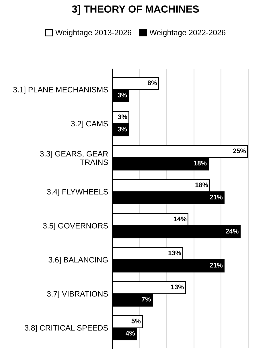
3.1] Kinematic and dynamic analysis of plane mechanisms
22 questions
A slider-crank mechanism with crank radius 60 mm and connecting rod length 240 mm is shown in Figure 1(a). The crank is rotating with a uniform angular speed of 10 rad/s, counterclockwise. For the given configuration, determine the speed of the slider. A and B in Figure 1(a) are at the same horizontal level.
[Figure: Figure 1(a) – Slider-crank mechanism: crank AO = 60 (mm) pinned to the ground at A, rotating counterclockwise (curved arrow); connecting rod OB = 240 (mm) joining the crank end O to the slider B, which moves on a horizontal guide (labelled ‘Slider’); the angle between crank AO and connecting rod OB at O is 90°; A and B are at the same horizontal level] [2022/10m/1a]
In a slider-crank mechanism, the lengths of the crank and connecting rod are 150 mm and 600 mm respectively. Locate all the I-centres of the mechanism for the position when the crank has turned 30° from IDC. Also, find the velocity of the slider and the angular velocity of the connecting rod, if the crank rotates at 30 rad/s. [2021/15m/2a]
A five-bar chain is shown in the figure. Prove that it is an unconstrained chain.
[Figure: Closed pentagonal chain of five links numbered 1 to 5 connected by five pin joints: link 1 at the bottom (horizontal), link 2 on the left rising from the left end of link 1, link 3 along the top left, link 4 along the top right, link 5 on the right connecting back to the right end of link 1] [2020/5m/1c(i)]
Show that the chain shown in the figure is not a kinematic chain.
[Figure: Chain with six joints A, B, C, D, E, F and nine links numbered 1 to 9: link 1 = AD (bottom, horizontal), link 2 = AB, link 3 = BC (horizontal), link 4 = CD (vertical, right side), link 5 = CE, link 6 = BE, link 7 = FE (top, horizontal), link 8 = FB, link 9 = FA (vertical, left side); joint B lies inside the outline and is common to links 2, 3, 6 and 8] [2020/5m/1c(ii)]
(i) A kinematic link may consist of many resistant bodies having no relative motion between them. Explain this statement considering the mechanism used in an internal combustion engine. (ii) Explain, with the help of a neat sketch, the equivalent lower-pair mechanism of a cam-translating follower mechanism. (iii) Some four-bar linkages are shown in Figure 2(c), where the number indicates the respective link length (in cm). Identify the nature of each mechanism i.e. whether it is A. double crank, B. crank-rocker, or C. double rocker.
[Figure 2(c): Three four-bar linkages, each with the bottom link fixed (hatched). A: fixed link 10, left link 16, top (coupler) link 20, right link 18. B: fixed link 24, left link 16, top (coupler) link 30, right link 20. C: fixed link 20, left link 16, top (coupler) link 10, right link 18 (all lengths in cm)] [2019/15m/2c]
Draw a cranked-slider quick return mechanism and explain its principle with figure. [2015/10m/1a]
In the figure shown, the end A of a bar AB, is constrained to move along vertical path AD and the bar passes through a swivel bearing pivoted at C. When A has a velocity of 3 m/s towards D and an acceleration of in the opposite direction, determine: (i) velocity and acceleration of sliding of bar through the swivel, (ii) angular velocity and angular acceleration of AB.
[Figure: End A of bar AB moves on a vertical line through D, with A above D; the swivel bearing C is pivoted at the same level as D, 0.4 m horizontally from D. The bar runs from A down through the swivel at C and extends beyond it to B; at the instant shown the bar makes 30° with the horizontal line DC at C.] [2013/25m/4a]
A band brake is used to stop a machine. The brake band is in contact with the brake drum through an angle of 250°. The coefficient of the friction is 0.3. Determine the force P required to develop the braking torque of magnitude 400 Nm. The arrangement is shown in the above figure.
[Figure: Band brake (printed above the text of 1(e)) – brake drum of radius 20 cm rotating clockwise; the band wraps the upper part of the drum and its two straight ends run down to a horizontal lever below the drum: one end is attached at A, the left end of the lever, which is the fulcrum (pin), the other end at B, 5 cm to the right of A; the lever extends to the right to C, where an upward force P is applied; horizontal distance from B to the line of action of P at C = 40 cm] [2012/12m/1e]
What type of motion is performed by a point on the surface of a football rolling on the ground and a point on the surface of a nut moving over a threaded bolt? [2010/4m/1c(ii)]
What is a quick-return mechanism? Give its types and applications. How is the ratio of time of cutting stroke to return stroke calculated for a slotted lever and crank type of quick-return mechanism? Explain with the help of a neat sketch. [2010/15m/2b(i)]
Write down the expressions for the friction torque in case of flat pivots based on (i) uniform pressure theory and (ii) uniform wear theory. Explain their relevance in design. A single-plate clutch transmits 25 kW at 900 r.p.m. The maximum pressure intensity between the plates is . The outer diameter of the plate is 360 mm. Both the sides of the plate are effective and the coefficient of friction is 0.25. Determine – (1) the inner diameter of the plate; (2) The axial force to engage the clutch. [2008/20m/200w/1b]
(i) What is creep of belt in a belt drive? Explain it with the help of a neat sketch. (ii) A leather belt 100 mm wide and 10 mm thick is transmitting power at 1000 m/min. The net driving tension is 1.8 times the tension on the slack side. If the safe permissible stress on the belt section is , calculate the maximum power that can be transmitted at this speed. Assume the density of leather equal to . [2007/30m/2b]
A compressor requires 120 kW to run at 240 rpm from an electric motor of speed 750 rpm, by means of a V-belt drive. The diameter of the compressor shaft pulley should not be more than 1000 mm while the centre distance between the shafts is 2000 mm. The belt speed should not exceed 25 m/sec. Determine the number of V – belts required to transmit the power, if each belt has a cross sectional area of , density and an allowable tensile stress of 2.5 MPa. The pulley groove angle is 40° and coefficient of friction between the belt and pulley sides is 0.25. [2006/30m/2b]
The link AB of a mechanism is 40 cm long and weights 30 N. It is undergoing plane motion in X-Y plane and the accelerations of its ends are: at 10° from X-axis in counter clockwise direction, at 60° in counter clockwise direction from AB (Refer the above figure). The centre of gravity of the link is at G where AG = 20 cm. The radius of gyration of the link about Z-axis through G is 12 cm. Determine the forces and applied at A and B respectively to give above-mentioned accelerations, if has a horizontal component of 60 N towards right.
[Figure (printed above the text): X–Y axes with origin at A. Link AB rises from A at 45° to the X-axis; G is a point on AB between A and B. At A the acceleration is drawn as an arrow at 10° above the X-axis. At B the acceleration is drawn as an arrow pointing vertically downwards, with the angle between BA and marked 60°.] [2004/20m/1a]
A flat belt drive is to transmit 110 kW at a belt speed of 25 m/s between two pulleys of diameter 250 mm and 400 mm. The centre distance between the pulleys is 1 m. The permissible stress in the belt is 8.5 . Thickness to width ratio of the belt is 0.1 and the density of the belt material is 1100 . The coefficient of friction between the belt and pulleys is 0.3. Determine the minimum required belt width. What would be the necessary installation force between the pulley bearings and the force when full power is being transmitted? [2003/20m/1c]
What do you understand by inversions of a mechanism? Show two inversions of a slider crank mechanism with the help of neat sketches. [2001/20m/1a]
In a slider crank mechanism the crank length is 10 cm and the connecting rod is 40 cm long. The crank rotates in anticlockwise direction at a constant speed of 600 r.p.m. Find the acceleration of the slider and the angular acceleration of the connecting rod at an instant when the crank is past the inner dead centre by 45°. [1999/30m/3b]
What is coriolis acceleration? Find the magnitude and direction of this acceleration in the following cases.
[Figure: Fig-1, two sketches, (i) and (ii), each with x and y axes. (i) A rod through the origin inclined at about 45° to the x-axis, rotating about the origin with angular velocity ω (marked by a curved arrow at the origin); a slider on the rod moves along the rod away from the origin with velocity V (arrow pointing up the rod). (ii) The same arrangement with ω marked by a curved arrow at the origin; the slider moves along the rod towards the origin with velocity V (arrow pointing down the rod). The sense of ω in each sketch cannot be read with certainty from the copy [?]] [1997/20m/200w/1a]
What is the effect of centrifugal force of the Transmission of power in a belt drive? A prime mover running at 300 r.p.m., drives a d.c. generator at 500 r.p.m. by a belt drive. Diameter of the pulley at the output shaft of the prime mover is 600 mm. Assuming a slip of 3%, determine the diameter of the generator pulley if the belt running over it is 6 mm thick. [1997/30m/2a]
Develop an equation for the relationship between the angular velocities of the input and output cranks of a four-bar linkage. [1997/30m/4b]
Differentiate between kinematic analysis and synthesis. What is the significance of Chebyshev spacing points and how can you obtain them? Draw and explain the working of any one mechanism generating exact straight line. [1996/20m/200w/1b]
What is Arnold-Kennedy theorem of three centres? State its importance in kinematic analysis of mechanisms. [1995/20m/200w/1b]
3.2] Cams
7 questions
Enumerate different types of cams and followers commonly used. State their relative merits and demerits. [2024/10m/4c]
A cam drives a flat reciprocating follower in the following manner: During first 120° rotation of the cam, the follower moves outwards through a distance of 20 mm with simple harmonic motion. The follower dwells during next 30° of cam rotation. During next 120° of cam rotation, the follower moves inwards with simple harmonic motion. The follower dwells for the next 90° of cam rotation. The minimum radius of the cam is 25 mm. Draw the profile of the cam. [2014/20m/2c]
Sketch the displacement, velocity and acceleration curves for rise motion alone if the cam-follower is executing uniform and equal acceleration and retardation. State the main disadvantage of this type follower motion. [2011/10m/1c]
Distinguish between the pressure angle of a radial cam and that of a spur gear, with the help of a sketch. [2010/8m/1c(i)]
(i) Define pressure angle for a cam follower mechanism. Explain its importance in the design of cam profile. (ii) A plate cam drives a radial translating follower with cycloidal motion at 1000 rpm. Rise and return strokes are each 120° with two equal dwells. Follower is retained against the cam by a compression spring with a scale of 15 N/mm. Spring is compressed by 2.5 mm in assembly to provide an initial load. For a rise of 10 mm and a follower mass of 1.8 kg, compute the radial component of the cam force and the cam shaft torque at a point located at 100° in the ascending stroke. [2007/20m/1a]
Define the following terms commonly used in laying out the cam profiles: (i) Base circle (ii) Trace point (iii) Pitch curve (iv) Pressure angle. The following notations refer to a Tangent cam with straight flank, circular nose and roller follower: = Base circle radius; = Roller radius; = Nose radius; = Semi-angle of action of the cam; = Angle by which cam rotates for contact for roller with the flank; = Any angle by which the cam has rotated; h = Lift or the stroke at an angle . Draw a neat sketch of this cam. Determine the expressions for evaluating the lift (h), velocity (v) and the acceleration of the follower when the cam has turned through an angle (which is less than ). [2006/20m/1a]
Explain with the help of velocity-and acceleration diagrams why cycloidal profile is preferred over simple harmonic motion profile for cams used in high speed applications. [1998/20m/200w/1b]
3.3] Gears and gear trains
31 questions
In a gear drive, the power component is 0.94 times the normal thrust with the addendum for stub teeth being 85% of the module. Determine the minimum number of teeth to avoid undercutting and length of path of contact in terms of module, m, if: (i) The gear ratio is unity. (ii) The gear ratio is 2.5. [2026/10m/1d]
A pair of involute profile spur gears in mesh have to give a speed ratio of 2. The pressure angle is 20° and the module is 10 mm. The pinion has 24 teeth and drives the larger gear. If the addenda on pinion and gear wheels are equal to one module, determine: (i) length of path of contact, (ii) contact ratio, and (iii) angle of action of the pinion. [2025/10m/1e]
In an epicyclic gear train of the sun and planet type shown in the figure below, the annular gear ‘A’ meshes internally. The three identical planet wheels ‘P’ of equal size, mesh with annular gear ‘A’ and the sun wheel ‘S’. The planet wheels are carried by a star shaped spider ‘C’. The size of the different toothed wheels are such that the spider ‘C’ which carries the planet wheels is to make one revolution for every 5 rotations of the spindle carrying the sun wheel ‘S’, when the gear ‘A’ is stationary. If the minimum number of teeth on any wheel is 14, determine the number of teeth for all the wheels. Further, if the driving torque on the sun wheel is 200 N-m, determine the fixing torque required to keep the annular gear ‘A’ stationary.
[Figure: Epicyclic gear train: central sun wheel S on the central axis C; three identical planet wheels P equally spaced at 120°, each meshing with S and internally with the annular gear A; the planet pins are carried by a three-armed (star-shaped) spider labelled “Spider” (C).] [2025/10m/4c(i)]
Two involute gears in mesh have pressure angle of 20° and module of 6 mm. The number of teeth on pinion is 28 and the larger gear has 52 teeth. Calculate the following: (i) Contact ratio (ii) Angle of action of gear wheel and pinion (iii) Ratio of sliding velocity to rolling velocity at (I) Starting of contact, (II) Pitch point, (III) End of contact. Consider the addenda on pinion and gear wheel as equal to one module. [2023/20m/4a]
Two meshing spur gears with pressure angle of the involute teeth being 20° have addendum equal to one module. The pinion has 14 teeth and the larger gear has 54 teeth. Does the interference occur? If it occurs, what should be the change in the pressure angle in order to eliminate interference? Take standard module = 10 mm. [2022/10m/1e]
In the epicyclic gear train shown in the figure, the wheel ‘C’ is keyed to the shaft ‘B’. ‘D’ and ‘E’ are compound gears. ‘C’, ‘D’ and ‘E’ have 35, 65 and 32 teeth respectively. All the gears have same module. If ‘A’ and ‘B’ rotate at 60 rpm and 28 rpm respectively in opposite directions, find the speed and direction of rotation of arm ‘G’.
[Figure: Sectional view of a compound epicyclic gear train with two coaxial shafts: shaft B (left) and shaft A (right, in a bearing). Wheel C is keyed to shaft B; wheel F is mounted on shaft A, coaxial with C. Arm G is mounted on shaft B (free to turn) and extends upward to carry a pin (parallel to the shafts, shown by a dash-dot line) on which the compound gear D–E rotates; D meshes externally with C and E meshes externally with F. Number of teeth of F is not given] [2021/10m/1d]
Determine the number of teeth and the speed of the pinion where the driven gear wheel has 60 teeth of 10 mm module and rotates at 300 rpm. The two spur gears have a velocity ratio of . Also compute the pitch line velocity. [2020/10m/2b(i)]
Two parallel shafts, about 600 mm apart, are to be connected by spur gears. One shaft is to run at 360 rpm and the other at 120 rpm. Design the gears, if the circular pitch is to be 25 mm. [2020/10m/2b(ii)]
In an epicyclic gear train, gear A has 15 teeth and is rigidly fixed to the motor shaft. The gear B has 20 teeth and meshes with A and also with fixed wheel D which has 55 teeth. Gear C has 15 teeth and is integral with B. Gear C meshes with gear E which is keyed to the machine shaft. The gear E has 50 teeth. The arm rotates about the same axis on which A is mounted and carries the compound wheels B and C. Arrangement is shown in Figure 3(c) given below. If the motor runs at 1000 rpm, find the speed of the machine shaft.
[Figure 3(c): Concentric arrangement: fixed internal wheel D (outermost circle, hatched support at bottom) and internal gear E (inner large circle) about the central axis of sun gear A; an arm from the centre of A carries the compound wheel B–C on a pin; B (larger) meshes with A and with D, C (smaller, on the same pin as B) meshes with E] [2019/15m/3c]
Two gear wheels having 20 and 40 teeth (involute) are in a mesh. Given: Pressure angle = 22.5° Module = 12 mm Determine the addendum for each gear wheel and the contact ratio if the line of contact on each side of the pitch point is half of the maximum possible length on that side. [2019/20m/4a]
Two involute gears in a mesh have a module of 8 mm and pressure angle of 20°. The larger gear has 57 while the pinion has 23 teeth. If the addenda on pinion and gear wheels are equal to one module, find the following: (i) Contact ratio (The number of pairs of teeth in contact) (ii) Angle of action of the pinion and the gear wheel (iii) Ratio of the sliding to rolling velocity at the I. Beginning of contact II. Pitch point III. End of contact. [2018/20m/2b]
A compound epicyclic gear is shown in Fig. 3(b). Gears A, D and E are free to rotate on axis P. Compound gears B and C rotate together on axis Q at the end of arm F. All the gears have equal pitch. The number of external teeth on gears A, B and C are 18, 45 and 21 respectively. Gears D and E are annular gears. Gear A rotates at 100 r.p.m. in counter-clockwise direction and gear D rotates at 450 r.p.m. clockwise. Find the speed and direction of arm F and gear E.
[Figure: Fig. 3(b) – Front view of the compound epicyclic train: sun gear A at the centre on axis P; arm F extends from P down to axis Q; compound gear B (larger) and C (smaller) on axis Q, with B meshing with A; two concentric annular gears surround the train, D (inner annulus) and E (outer annulus).] [2017/15m/3b]
A compound gear train comprising the input shaft driven by a motor at 1425 rpm in clockwise direction is shown in the figure. The arrangement and the number of teeth on the gears is shown in the figure. Determine the speed of the output shaft and the direction of rotation of the output shaft.
[Figure: Compound gear train with all gear centres on one horizontal centre line: gear 1 (, on the input shaft) meshes with gear 2 (); gear 3 () is on the same shaft as gear 2 and meshes with gear 4 (); gear 5 () is on the same shaft as gear 4 and meshes with gear 6 (, on the output shaft)] [2016/10m/1e]
Explain the fundamental law of gearing with a neat sketch. [2015/10m/1b]
An epicyclic gear train consists of a pinion, a wheel of 40 teeth and an annulus with 84 internal teeth concentric with the wheel. The pinion gears with the wheel and the annulus. The arm that carries the axis of the pinion rotates at 100 rpm. (i) Find the speed of the wheel. (ii) Find the speed of the annulus, if the wheel is fixed. [2015/20m/3a]
A pinion having 30 teeth drives a gear having 80 teeth. The profile of the gears is involute with 20° pressure angle, 12 mm module and 10 mm addendum. Find the length of path of contact, arc of contact and contact ratio. [2014/10m/1d]
An epicyclic speed reduction gear schematic is shown in Fig. 4(c). Compound wheel B–C is free to rotate on pin A connected to driving shaft. Wheel ‘C’ meshes with fixed wheel ‘E’ and wheel ‘B’ meshes with wheel ‘D’ keyed to driven shaft. If number of teeth on wheels are , , and , determine the ratio of speeds of the driving and driven shafts.
[Figure: Fig. 4(c) – Schematic: the driving shaft (left) is cranked to form arm A, which carries a pin on which the compound wheel B–C rotates freely (B the larger wheel, C the smaller, both above the axis). B meshes with wheel D keyed to the driven shaft (on the common axis); C meshes with wheel E, which is fixed to the frame (hatched). The driven shaft emerges to the right through the fixed frame.] [2014/20m/4c]
In the epicyclic gear train shown in the Figure, is the driver, is connected to output. and are annulus gears, and and are external gears, in which is fixed gear. Given the tooth numbers of gears are , , and , determine the velocity ratio of the co-axial shafts. Determine also the magnitude and direction of the torque required to fix , if a torque of 300 N-m is applied in a clockwise direction to .
[Figure: Sectional sketch of a compound epicyclic gear train on a common axis: sun on the input shaft (left) meshes with planets that also mesh with annulus ; a second gear set has sun on a fixed (hatched) sleeve around the shaft, meshing with planets that also mesh with annulus ; the planets of the two sets are carried on pins (shown dashed) of a common carrier, and is connected to the output shaft (right).] [2013/20m/3c]
1. Define interference in involute gears. 2. How do you prevent interference? 3. Determine the minimum number of teeth required on a pinion, in order to avoid interference which is to gear with an equal wheel. The pressure angle is 20° and a standard addendum of 1 module for the wheel may be assumed. [2012/15m/2a(i)]
1. Sketch the arrangement of a reverted gear train comprising of gears and mounted on co-axial driving and driven shafts, respectively. Gears and are mounted on a parallel counter shaft to mesh with gears and , respectively. 2. The speed ratio (driving speed ÷ driven speed) in the reverted gear train of above arrangement is to be 14. The module pitch of gears and are 3.125 mm and of gears and are 2.5 mm. Calculate the suitable numbers of teeth for the gears. No gear is to have less than 24 teeth. The centre distance between the counter-shaft and driving shaft is 200 mm. [2012/15m/2a(ii)]
A simple gear train consists of three spur gears 1, 2 and 3, where gear 1 is the driver, gear 2 idler gear and gear 3 driven gear. The axes of all the 3 gears are in the horizontal plane. The bearing centres of gears 1, 2 and 3 are designated as A, B and C respectively. Gear 1 has 10 mm module, pressure angle 20° and 35 teeth. Gears 2 and 3 are having 45 teeth and 60 teeth respectively. The driver is rotating at 1000 rpm clockwise and delivers 30 kW of power. Find: (i) distance between A and C (ii) speed ratio of the gear train. Draw the free body diagram of the driven gear and show all the forces acting on it. [2011/10m/4b]
Distinguish between the pressure angle of a radial cam and that of a spur gear, with the help of a sketch. [2010/8m/1c(i)]
Which type of epicyclic gear train is used for rear wheel drive of automotive trucks? Show that rpm of the propeller shaft is arithmetical mean of rpm of two rear wheels, while negotiating a road curve. [2010/15m/2b(ii)]
State why gear teeth have to be undercut. [2009/4m/2a(i)]
The following data refers to two 20° involute spur gears in mesh externally: Velocity ratio = 3; Module = 3 mm; Addendum = 1.1 module. If the pinion rotates at 120 r.p.m., find– (1) the minimum number of teeth on each gear wheel to avoid interference; (2) the number of pairs of teeth in contact. [2009/16m/2a(ii)]
Two mating gear wheels of module 6 mm have 19 and 47 teeth of 20° obliquity and with addenda of 6 mm. Find the number of pairs of teeth in contact and the angle turned through by the larger wheel while one pair of teeth is in contact. Explain carefully the advantages obtained by increasing the addendum height for the smaller wheel while maintaining the same working depth. [2008/20m/200w/1a]
Explain the term ‘interference’ as applied to involute gears. How could it be eliminated? Two standard full depth involute gears have module of 5 mm. The pinion has 15 teeth while the gear has 60 teeth. Addendum is equal to the module. (i) Show that the gear will interfere with the pinion (ii) To what value should the pressure angle be increased in order to eliminate the interference? [2004/30m/2b]
Fig. 1 shows a planetary gear train that has two inputs and ; Sun gear 2 rotates at 500 r.p.m. and the arm 6 rotates at 750 r.p.m. both clockwise as viewed from left. Determine the speed and direction of rotation of the output gear 5.
[Figure: Fig. 1 – Planetary gear train. Input shaft entering from the left carries the sun gear 2 (18 T) and is driven at ; the arm 6 is mounted on a hollow shaft around the input shaft (supported in the left frame bearing 1) and is driven at . The arm carries a compound planet consisting of gear 3 (22 T), meshing with sun gear 2, and gear 4 (25 T), meshing with gear 5 (15 T). Gear 5 is fixed on the output shaft, coaxial with the input shaft, supported in the right frame bearing 1.] [2003/30m/2b]
A gear with 42 teeth and a pinion with 19 teeth are cut with involutes teeth of pressure angle 20° and module pitch 6 mm. The addendum of each wheel is 6 mm. Find: (i) the length of the arc of contact. (ii) the number of pairs of teeth in contact. (iii) the angle turned through by the pinion, while any one pair of teeth is in contact. (iv) the ratios of sliding velocity to the rolling velocity at the instant (a) the engagement commences, (b) the engagement terminates and (c) at the pitch point. [2002/30m/2a]
In an epicyclic gear train as shown in the figure given below, the arm A is fixed to the shaft S. The wheel having 100 teeth rotates freely on the shaft S and the wheel F with 150 teeth is separately driven. If the arm A runs at 200 rpm and the wheel F at 100 rpm in the same direction, find (i) Number of teeth on wheel C and (ii) Speed of wheel B.
[Figure: Epicyclic gear train drawn as concentric circles about the shaft S at the centre: an inner wheel B mounted on S, an outer annular (internal) wheel F, and two planet wheels C (one at the top, one at the bottom) meshing between B and F; the arm A is a vertical bar through the centre S carrying the two planets C at its ends.] [2000/30m/3a]
A spur gear pinion is driven by an electric motor of power 15 kW running at 740 r.p.m. pitch diameter of the pinion is 108 mm and speed reduction is 3:1. Module is 6 mm and the pressure angle is 20°. The pinion is mounted on a shaft located in symmetrical bearings over a span of 300 mm. The gear is overhanging by 50 mm on the left of two bearings 200 mm apart. Calculate the bearing reactions for the gear when the pinion rotates clockwise. [1997/30m/2b]
3.4] Flywheels
16 questions
The effective turning moment of a two-wheeler engine crankshaft for every 180° of crank rotation is represented by: where is the crank inclination with respect to the inner dead centre. A flywheel of 500 kg mass with radius of gyration of 750 mm is provided on the crank. Assuming external resistance as constant at an engine speed of 300 rpm, determine: (i) The maximum, minimum and mean torques. Also represent them on a diagram. (ii) The power developed. (iii) Total percentage fluctuation in speed. (iv) If, owing to size constraints, radius of gyration of the flywheel is reduced to 600 mm, will the percentage (%) fluctuation of speed increase? If yes, then by how much? [2026/20m/2c]
A punching press executes 10 holes per minute in a 25 mm thick plate. The diameter of each hole is 20 mm. The punch has a stroke of 60 mm and the punch moves with uniform velocity throughout. A flywheel is attached to the press and the mean speed of the flywheel is 25 m/s. If punching requires 10 N-m of energy per of the sheared area, find the power needed to operate the punching press. Further determine the mass of the flywheel required if the total fluctuation of speed is restricted to 5% of the mean speed. [2025/10m/3a(ii)]
The turning moment curve for one revolution of a multicylinder engine above and below the line of mean resisting torque are given by –30, +360, –250, +300, –300, +250, –380, +260 and –210 . The vertical and horizontal scales are 1 mm = 600 N-m and 1 mm = 5°, respectively. The fluctuation of speed is limited to ±1.5% of mean speed which is 250 rpm. The hoop stress in rim material is limited to . Neglecting the effect of boss and arms, determine the suitable diameter and cross-section of flywheel rim. The density of rim material is . Assume width of rim equal to four times its thickness. [2024/20m/2b]
The cranks of a three-cylinder single acting engine are set equally at 120°. The engine speed is 540 rpm. The turning moment diagram for each cylinder is a triangle for the power stroke with a maximum torque of 100 Nm at 60° after dead-centre of the corresponding crank. On the return stroke, the torque is sensibly zero. Determine the: (i) power developed by the engine (ii) coefficient of fluctuation of speed if the flywheel has a mass of 7.5 kg with a radius of gyration of 65 mm (iii) coefficient of fluctuation of energy (iv) maximum angular acceleration of the flywheel. [2022/20m/2c]
A single cylinder, four-stroke engine develops 20 kW at 250 rpm. The work done by the gases during the expansion stroke is 3 times the work done on the gases during the compression stroke. The work done during the suction and exhaust strokes may be neglected. During expansion and compression strokes the turning moment curve is assumed to be triangular. If the flywheel has a mass of 1500 kg and has a radius of gyration of 0.6 m, find the coefficient of fluctuation of speed. [2021/20m/3c]
The turning-moment diagram for a petrol engine is drawn to a vertical scale of 1 mm = 500 Nm and a horizontal scale of 1 mm = 3°. The turning-moment diagram repeats itself after every half revolution of the crank shaft. The areas above and below the mean torque line are + 270, – 590, + 100, – 390, + 870 and – 260 mm. The rotating parts have a mass of 50 kg and radius of gyration of 2.2 m. If the engine speed is 1500 rpm, determine the coefficient of fluctuation of speed. [2019/10m/1e]
A steam engine develops 300 kW power at 9.5 rad/s. The coefficient of fluctuation of energy is found to be 0.1 and fluctuation of speed is kept within ±0.5% of mean speed. Find the mass of the flywheel required if the radius of gyration is 2 m. [2017/10m/1d]
The turning moment diagram of a multi-cylinder reciprocating engine is drawn to scale: 1 mm = 500 N-m, Y-axis and 1 mm = 4°, X-axis. The areas above and below the mean torque line are: + 50, – 120, + 95, – 140, + 90, – 70 and + 95 , when the engine is running at 1000 rpm. If the mean fluctuation of speed is not to exceed ± 1% of the mean speed, determine the mass of the flywheel of radius of gyration of 400 mm. [2016/20m/4c]
A riveting machine is driven by a constant torque 4 kW motor. Each riveting operation takes 1 second and requires 9000 N-m of energy. A flywheel of mass 130 kg and radius of gyration 0.5 m is fitted to the riveting machine. If the speed of the flywheel is 420 rpm before riveting, find (i) the fall in the speed of the flywheel after riveting, (ii) the number of rivets fitted per hour. [2015/20m/4b]
Because of nature of its operations, the load torque of a machine is intermittent as follows: During its three quarter revolution, the load torque increases uniformly from 10 kNm to 15 kNm. Thereafter it remains constant for half revolution and then decreases uniformly in three quarter revolution to 50 kNm. After this for one revolution it remains constant. Thus the cycle is repeated. The machine is run by a constant torque motor running at a speed of 300 rpm, in conjunction with a flywheel of mass moment of inertia of . Determine: (i) Magnitude of mean torque of motor (ii) Power of the motor (iii) Speed fluctuation of the system. [2014/20m/3c]
Distinguish clearly the function of a flywheel used in I.C. Engines and in mechanical punching presses. For the same power output, why flywheels of multi-cylinder inline engines are relatively smaller than that of single cylinder engine? [2013/10m/1d]
State the function of a flywheel. [2009/4m/4a(i)]
A punching machine carries out 5 holes per minute. Each hole of 40 mm diameter in 40 mm thick plate requires 10 N-m of energy/ of the sheared area. The punch has a stroke of 100 mm. Find the power of the motor required, if the mean speed of the flywheel is 25 m/s. If the total fluctuation of speed is not to exceed 4% of the mean speed, determine the mass of the flywheel. [2009/16m/4a(ii)]
The turning moment diagram for a quadruple expansion marine engine drawn to the following scales: 1 cm = 15 ton-m and 1 cm = 15°. The areas of the loops above and below the mean turning moment line taken in order are 0.12, 0.34, 0.91, 0.81, 0.15, 0.18, 1.86 and 1.71 . If the moment of inertia of the propeller and entrained water is 100 and the mean speed of rotation is 100 r.p.m., what is the value of the coefficient of fluctuation of speed? [2005/20m/1a]
A press has to punch 30 holes per minute and the motor delivers 1.5 kW to the press uniformly. If the actual punching of each hole is accomplished during 30° of crank rotation of the punching machine and the fluctuation of speed is not to exceed ±10%, determine the minimum moment of inertia of the flywheel which is directly mounted on the crankshaft. Neglect the intertia of the rest of the system. [2003/30m/2a]
A punching press is drived by a constant torque electric motor. The press is provided with a flywheel that rotates at a maximum speed of 225 rpm. Radius of gyration of the flywheel is 0.5 m. The press punches 70 holes per hour; each punching operation takes 2 seconds and requires 15 kN-m of energy. Find the power of the motor and the minimum weight of the flywheel if the speed of the same is not to fall below 200 rpm. [2000/30m/2b]

Preparing for Prelims too?
Our UPSC Prelims Topic-wise PYQ eBook covers every Prelims question with detailed explanations, so you can see exactly where UPSC asks from.
View the BookDownload Free Sample3.5] Governors
18 questions
In a Proell governor with open arms, the mass of each ball is 7 kg and the mass of the sleeve (central load) is 140 kg. The length of each arm is 180 mm and the length of extension of lower arms to which the balls are attached is 90 mm. The distance of pivots of the arms from axis of rotation is 25 mm and radius of rotation of the balls is 190 mm when the arms are inclined 40° to the axis of rotation. Determine the equilibrium speed for the given configuration. Further, if the frictional effect is included by incorporating a frictional force of 40 N at the sleeve, determine the coefficient of insensitiveness and range of speed when the governor is insensitive. [2025/20m/2b]
A governor of Hartnell type has each ball of weight 20 N and the lengths of vertical and horizontal arms of the bell crank lever are 125 mm and 65 mm, respectively. The fulcrum of the bell crank lever is at a distance of 100 mm from the axis of rotation. The maximum and minimum radii of rotation of the balls are 125 mm and 80 mm, and the corresponding equilibrium speeds are 325 rpm and 300 rpm, respectively. Find the stiffness of the spring and the equilibrium speed when the radius of rotation is 100 mm. [2024/20m/4a]
The length of each arm of a Porter governor is 350 mm. The lower arms are attached to a sleeve at a distance of 25 mm from the axis and the upper arms are pivoted on the axis of rotation. The load on the sleeve is 250 N and the weight of each ball is 25 N. If the radius of rotation of the balls is 125 mm at a speed of 225 rpm, then calculate the following: (i) Speed of governor after the sleeve has lifted 55 mm (ii) Effort (iii) Power of the governor. [2023/20m/2b]
In a Hartnell governor, the lengths of ball and roller arms of the bell crank lever are 100 mm and 80 mm respectively. Each ball has a mass of 1.5 kg. The extreme radii of rotation of the balls are 90 mm and 140 mm. The minimum equilibrium speed is 840 rpm and the maximum equilibrium speed is 5% greater than this. Assuming the sleeve to be of negligible mass and neglecting friction and obliquity of arms, determine: (i) Spring stiffness (ii) Initial compression of the central spring (iii) Equilibrium speed corresponding to radius of rotation of 130 mm. [2022/20m/3c]
The arms of a Porter governor are 300 mm long. The upper arms are pivoted on the axis of rotation. The lower arms are attached to a sleeve at a distance of 40 mm from the axis of rotation. The mass of the load on the sleeve is 70 kg and the mass of each ball is 10 kg. Determine the equilibrium speed when the radius of rotation of the balls is 200 mm. If the friction is equivalent to a load of 20 N at the sleeve, what will be the range of speed for this position? [2020/20m/3b]
The arms of a Hartnell governor are of equal length. When the sleeve is in the mid-position, the masses rotate in a circle with a diameter of 150 mm (the arms are vertical in the mid-position). Neglecting friction, the equilibrium speed for this position is 360 rpm. Maximum variation of speed, taking friction into account, is to be 6% of the mid-position speed for a maximum sleeve movement of 30 mm. The sleeve mass is 5 kg and the friction at the sleeve is 35 N. Assume that the power of the governor is sufficient to overcome the friction by 1% change of speed on each side of the mid-position. While neglecting obliquity effect of arms, find the following: (i) Mass of each rotating ball (ii) Spring stiffness (iii) Initial compression of the spring. [2018/20m/3c]
A Porter governor having all arms of 240 mm length is pivoted on the axis of rotation. Each ball has a mass of 5 kg and the load on the sleeve is 18 kg. The ball path is 150 mm when the sleeve begins to rise and 200 mm at the maximum speed. Find the following: (i) Range of speed (ii) Coefficient of sensitiveness, if the friction at the sleeve is equivalent to a force of 10 N. [2017/20m/4c]
Discuss criteria of stability for spring controlled governors. [2012/5m/4b(i)]
The sleeve arm and the ball arm of a Hartnell governor are 9 cm and 10 cm long respectively. At mean position of the sleeve, the equilibrium speed is 300 rpm and balls rotate at the radius of 12 cm. The mass of each ball is 2 kg and the sleeve movement is ± 2 cm from the mean position. The minimum speed is 96% of the mean speed. Determine the stiffness of the spring and the maximum speed of the governor. [2012/15m/4b(ii)]
What is the difference between centrifugal and inertia type of governors? Which one is more sensitive? Why is the former preferred to the latter? [2010/3m/1b(ii)]
(i) Explain the concept of controlling force in connection with a centrifugal governor and state its importance in determining the stability of a centrifugal type governor. (ii) In a spring loaded governor of Hartnell type, the mass of each ball is 1 kg. The length of the vertical arm of the bell crank lever is 100 mm and that of horizontal arm is 50 mm. The distance of the fulcrum of each bell crank lever is 80 mm from the axis of rotation of the governor. The extreme radii of rotation of the balls are 75 mm and 112.5 mm. The maximum equilibrium speed is 5 per cent greater than the minimum which is 360 rpm. Find initial compression of the spring and mass of the sleeve neglecting obliquity of the arms. Also find the equilibrium speed corresponding to the radius of rotation equal to 100 mm. [2007/30m/2a]
An automobile fitted with a spring loaded Hartnell governor, the flyballs of it rotate at 500 r.p.m. having radius of rotation of 7 cm with sleeve in mid-position and balls arms vertical. The length of ball and sleeve arms is same. The maximum sleeve movement is 2 cm with ±5% variation in speed. The mass of the sleeve is 5 kg and the friction may be assumed to be equivalent of an additional load of 30 N at the sleeve. The effort of governor is sufficient to overcome the friction of the sleeve caused by 1% change of speed at mid-position. Calculate– (i) the mass of flyballs; (ii) the spring rate; (iii) the initial compression of the spring; (iv) the governor effort for 1 % change of speed; (v) the power of governor. [2005/30m/2a]
In a spring controlled governor, mass of each governor ball is 7 kg and moves radially under the action of a controlling force F. If the speed range is 420 RPM to 440 RPM with range of ball path radius r equal to 12.4 cm to 132 cm. determine the linear relationship between ball path radius and controlling force. Sketch the graph between F and r. What is the equilibrium speed at r = 12.8 cm. [2001/20m/2a]
In a Hartnell governor where a central spring under initial compression is used for control, under what conditions does the governor become unstable? Also explain the effect of friction between the sleeve and spindle on the performance of the governor. [1999/30m/2a]
The controlling force curve of a spring-controlled governor is a straight line. The weight of each governor ball is 40 N and the extreme radii of rotation are 10 cm and 17.5 cm. If the values of the controlling force at the above radii are respectively 205 N and 400 N and the friction of the mechanism is equivalent to 2.5 N at each ball, find (i) the extreme equilibrium speeds of the governor; and (ii) the equilibrium speed and the coefficient of insensitiveness at a radius of 15 cm. [1998/30m/2a]
Deduce the condition under which a centrifugal governor becomes unstable. [1997/20m/200w/1b]
Define Effort and Power in relation to Governors. Obtain the expressions for these in the case of a Porter Governor. [1996/20m/200w/1c]
Explain the use of controlling force curves in the determination of stability of a centrifugal governor. [1995/20m/200w/1d]
3.6] Balancing
19 questions
A shaft carries three eccentric masses of 1 kg each at radial distances of 20, 30 and 20 mm with the central plane 50 mm apart. Their angular positions are 120° apart. If the shaft is balanced by adding two masses at a radius of 700 mm and at distances of 100 mm each from the central plane of the middle eccentric, (i) Determine the magnitudes and angular positions of the masses. (ii) If one of the masses is shifted to a radius of 50 mm due to space constraints, determine the change in its magnitude. Will there be any change in the mass and location of the other masses? [2026/20m/4b]
In a four cylinder symmetrical engine, the intermediate cranks are at 90° and each has a reciprocating mass of 500 kg. The engine is in complete primary balance. The centre distance between intermediate cranks is 600 mm and between extreme cranks is 1800 mm. The lengths of the connecting rods and cranks are 800 mm and 200 mm, respectively. Determine the masses fixed to the extreme cranks along with their relative angular positions. If the engine speed is 150 rpm, find the magnitude of secondary unbalanced forces. [2025/10m/4c(ii)]
A single-cylinder reciprocating engine has speed 250 rpm, stroke 300 mm, mass of the reciprocating parts 60 kg and mass of the revolving parts 50 kg at 150 mm radius. If two-thirds of the reciprocating parts and all the revolving parts are to be balanced, find (i) the balance mass required at a radius of 400 mm and (ii) the residual unbalanced force when the crank has rotated 60° from top dead centre. [2024/10m/1e]
A disc mounted on a shaft is having three masses of 6 kg, 5 kg and 4 kg, which are attached at a radial distance of 70 mm, 80 mm and 50 mm at the angular positions of 45°, 135° and 240° respectively. The angular positions are measured counter-clockwise from the reference line along the x-axis. Calculate the amount of countermass at the radial distance of 85 mm required for the static balance. [2023/10m/1b]
A shaft carries four masses A, B, C and D which are in complete balance. Masses C and D make angles of 90° and 210° respectively with that of mass B in the counterclockwise direction. The rotating masses A, B, C and D can be assumed to be concentrated at radii of 360 mm, 480 mm, 240 mm and 300 mm respectively. The masses B, C and D are 15 kg, 25 kg and 20 kg respectively and the planes containing B and C are 300 mm apart. Determine the following: (i) Mass A and its angular position (ii) Positions of planes A and D. [2022/20m/4c]
Four masses A, B, C and D revolve at equal radii and are equally spaced along a shaft. The mass B weighs 6 kg. Masses C and D make angles of 90° and 240° respectively with B in the same direction. Find the magnitude of the masses A, C and D and the angular position of A, if the system is in complete balance. [2021/20m/4c]
A rotor is completely balanced when masses of 2 kg and 1.2 kg are added temporarily in planes A and D each at 200 mm radius as shown in the figure. The balanced mass in the plane A is along the x-axis whereas in the plane D, it is at 120 mm radius. Determine the magnitudes and the directions of the masses B and C.
[Figure: Rotor shaft (drawn as an inclined line) with four planes A, B, C, D along it; axial spacing A to B = 350, B to C = 500, C to D = 250 (mm). In plane A the added mass (small circle) is along the x-axis (horizontal reference line); in plane D the added mass is shown on a radial line at an angle of 120° measured from the horizontal reference line] [2020/20m/4b]
Four masses A, B, C and D are attached to a shaft and revolve in the same plane. The masses are 12 kg, 10 kg, 18 kg and 15 kg respectively and their radii of rotation are 40 mm, 50 mm, 60 mm and 30 mm respectively. The angular positions of masses B, C and D are 60°, 135° and 270° from the mass A. Find the magnitude and position of balancing mass at a radius of 100 mm. [2017/20m/4a]
Four masses , , and are 160 kg, 225 kg, 200 kg and 312 kg, respectively. The corresponding radii of rotation are 0.25 m, 0.2 m, 0.3 m and 0.25 m, respectively. The angles between the successive masses are 45°, 75° and 135°. Find the position and magnitude of the balance mass required, if its radius of rotation is 0.25 m. Presume that all masses including the balance mass rotate in the same plane. [2012/10m/3d]
For a conventional type 2-stroke cycle four cylinder inline reciprocating engine, sketch the primary and secondary crank diagrams for firing order of I-II-IV-III and find out balancing condition of the engine for primary and secondary effects. [2011/10m/1b]
A shaft carries four rotating masses A, B, C and D in sequence along its axis. The masses A, B, C and D are assumed to be concentrated at radii of 12 cm, 16 cm, 8 cm and 10 cm, respectively. The masses of B, C and D are 30 kg, 50 kg and 40 kg, respectively. The planes containing B and C are 30 cm apart. The angular spacing of the planes containing C and D are 90° and 210°, respectively relative to B measured in the same sense. If the system is to be in complete dynamic balance, find– (i) the mass and angular position of mass A; (ii) the spacing positions of the planes containing A and B. [2009/20m/4b]
A shaft carries four masses in parallel planes A, B, C and D in order. The masses at B and C are 18 kg and 12.5 kg respectively and each has an eccentricity of 6 cm. The masses at A and D have an eccentricity of 8 cm. The angle between the masses at B and C is 100° and that between the masses at B and A is 190° (both angles measured in the same sense). The axial distance between the planes A and B is 10 cm and between B and C 20 cm. If the shaft is in complete dynamic balance, determine (i) the masses at A and D (ii) the distance between the planes C and D. (iii) the angular position of the mass at D. [2004/30m/2a]
A rotating shaft carries four masses A, B, C and D at radii of 10 cm, 12.5 cm, 20 cm and r cm respectively. The planes in which the masses revolve are spaced 60 cm apart. The masses B, C and D are known to be 10 kg, 5 kg and 4 kg respectively. It is desired that the rotating shaft should be in complete dynamic balance, For this to be achieved, determine: (i) required mass A (ii) the relative angular settings of the four masses, given that the angular spacing of the planes containing C and D are 118° and 260° respectively relative to B measured in the same sense. (iii) find the radius at which mass D is to be placed. [2002/30m/2b]
What do you understand by primary balancing and secondary balancing of multicylinder in line engines? Consider a six cylinder in line engine and show that it is fully balanced. [2001/20m/2b]
For a 90° V-twin engine system, having two identical cylinders with centre line of each cylinder being inclined at 45° to the vertical, the speed is 2400 r.p.m. The reciprocating mass per cylinder = 1.5 kg, stroke = 14 cm, length of connecting rod = 28 cm. Find the values of maximum primary and secondary forces, and indicate whether the same can be balanced by suitable means. [1999/30m/2b]
What do you understand by direct crank and reverse crank methods in balancing of engines? Explain with illustration, their significance with reference to balancing of radial engines. [1998/30m/2b]
The reciprocating mass per cylinder in a 60° V-twin engine is 1.2 kg. The stroke and the connecting rod length are 10 cm and 25 cm respectively. If the engine runs at 2000 r.p.m determine the maximum and minimum value of the primary and secondary forces. Also, find out the crank positions correspondence to these values. [1997/30m/4a]
Explain clearly the difference in the nature of unbalance caused by primary and secondary disturbing force in case of a reciprocating mass. What is the essential difference between unbalance caused by a reciprocating mass and that caused by a revolving mass? How will you achieve the complete balance in the case of a multi-cylinder in line engine? [1996/20m/200w/1a]
Obtain the expressions for primary and secondary forces for a V-twin engine having two identical cylinders lying in a plane. The included angle between the cylinder centre lines is . [1995/20m/200w/1a]
3.7] Vibrations
22 questions
Determine the damped natural frequency of the system shown in the figure.
[Figure: Rigid horizontal bar pivoted (hinged) at O. To the left of O at distance a, the bar end is connected to a vertical spring of stiffness k whose lower end is fixed to the ground at A. To the right of O at distance b, a vertical dashpot C is attached, its upper end fixed to a support B above. A point mass m is attached to the right end of the bar at distance l from O.] [2026/10m/3b(ii)]
The recoil mechanism of a gun consists of a critically damped spring-damper system. The maximum permissible recoil distance of the gun is specified as 0.5 m. If the initial recoil velocity of the gun is 10 m/s and the mass of the gun is 500 kg, determine the spring stiffness of the recoil mechanism and the critical damping coefficient of the damper. [2025/10m/3a(i)]
A shaft of span 1.5 m and diameter 20 mm is simply supported at the ends. It carries a 125 kg concentrated mass at midspan. If , calculate its fundamental frequency. [2024/10m/1b]
A mass weighing 100 N is suspended from a spring of constant k = 4000 N/m. At time t = 0, it has a downward velocity of 1 m/s as it passes through the position of static equilibrium. Determine the following: (i) The static spring deflection. (ii) The natural frequency of the system. (iii) The displacement (x) of the mass as a function of time, where x is measured from the position of static equilibrium. (iv) The maximum acceleration attained by the mass. [2021/15m/2b]
A circular cylinder of mass 4 kg and radius 15 cm is connected by a spring of stiffness 4000 N/m as shown in Figure 4(c) given below. It is free to roll on a horizontal rough surface without slipping. Determine the natural frequency.
[Figure 4(c): Cylinder of mass m resting on a horizontal rough floor; a horizontal spring of stiffness K connects the centre of the cylinder to a fixed vertical wall on the left; displacement X of the centre measured horizontally to the right] [2019/15m/4c]
In a single-degree damped vibrating system, a suspended mass of 8 kg makes 30 oscillations in 18 seconds. The amplitude decreases to 0.25 of the initial value after 5 oscillations. Determine the following: (i) Stiffness of the spring (ii) Logarithmic decrement (iii) Damping factor (iv) Damping coefficient. [2018/20m/4c]
A machine of mass 8 kg is supported on springs having combined stiffness of 54 N/mm. A dashpot is attached to the system that exerts a force of 40 N, when the mass has a velocity of 1 m/s. Determine the following: (i) Critical damping coefficient (ii) Damping factor (iii) Logarithmic decrement (iv) Ratio of two consecutive amplitudes. [2017/10m/1e]
A 110 kg machine is mounted on an elastic foundation of stiffness . When operating at 150 rad/s, the machine is subject to a harmonic force of magnitude 1500 N. The steady-state amplitude of the machine is measured as 1.9 mm. What is the damping ratio of the foundation? [2016/10m/4d]
A machine of mass 20 kg is mounted on springs and dashpot as shown schematically in the Figure 3(b). The total stiffness of the springs is 100 N/cm and the total damping is 1.5 . If the system is initially at rest and a velocity of 10 cm/sec is imparted to the mass, determine (i) the displacement and velocity of the mass as a function of time, (ii) the displacement and velocity at the time equal to one second.
[Figure: Figure 3(b) – Mass m (block) supported on a fixed ground by two springs, each of stiffness k/2, one on each side, and a dashpot L between them] [2015/20m/3b]
The vibrations of a machine of mass 76 kg are damped by a viscous dashpot which diminishes amplitude of vibrations from 17.2 mm to 3.2 mm in two complete oscillations. The machine is mounted on four springs each of stiffness 7.5 N/mm. Assuming that the damping force varies as the velocity, determine: (i) the damping coefficient, (ii) the ratio of frequencies of damped and undamped vibrations, and (iii) the periodic time of damped vibrations. [2014/10m/1e]
The mass of an electric motor is 100 kg. The mass of the armature alone is 30 kg and its centre of gravity lies 0.5 mm from the axis of rotation. The motor is mounted on five springs of negligible damping and the force transmitted to the floor is one-eleventh of the applied force. Assuming mass of the motor is equally distributed among the five springs, determine the (i) stiffness of each spring (ii) dynamic force transmitted to the floor. The motor is operating at a speed of 1400 rpm. [2013/10m/3b]
Briefly explain the following with examples and nail sketches: (i) Whirling of shafts (ii) Free, forced and damped vibrations of a single degree of freedom system. [2008/20m/2b]
A machine, of mass 17 kg, is mounted on a spring having stiffness 1 N/mm. A piston within the machine of mass 2 kg has a reciprocating motion with a stroke of 75 mm and a speed of 5000 rpm. Assuming the motion to be SHM, determine: (i) amplitude of motion of the machine. (ii) force transmitted to the ground. Damping ratio may be taken as 0.20. [2007/20m/1b]
A 350 N electronic instrument is attached to a ship deck which vibrates at an amplitude of 1.60 mm at 50 Hz. The instrument is to be isolated from the deck with four flexible mounts. Determine the required combined spring constant of the mounts such that the amplitude of vibration of the instrument is no more than 0.130 mm. If the springs are equal, what is the spring constant of each mount? What is the static deflection of each mount? [2006/30m/2a]
The disc of a torsional pendulum has a moment of inertia of 600 and is immersed in a viscous fluid. The brass shaft attached to it is of 10 cm diameter and 40 cm long. When the pendulum is vibrating, the observed amplitudes on the same side of the rest position for successive cycles are 9°, 6° and 4°. Find (i) logarithmic decrement, (ii) damping torque at unit velocity and (iii) the periodic time of vibration. Assume for brass shaft . What would be the frequency, if the disc is removed from viscous fluid? [2005/30m/2b]
A machine of mass 100 kg is supported on springs which deflect 8 mm under the static load. With negligible damping the machine vibrates with an amplitude of 5 mm when subjected to a vertical harmonic force at 80 per cent of the resonant frequency. When a damper is fitted it is found that the resonant amplitude is 2 mm. Determine: (i) the damping coefficient (ii) the critical damping coefficient (iii) damping ratio (iv) logarithmic decrement (v) the damping force. [2004/20m/1c]
In a vibrating system a coil spring of stiffness 50 N/mm supports a vibrating mass of 250 kg at the free end. In addition; the motion of mass is controlled by a dashpot whose resistance is proportional to velocity. From measurement it is found that the amplitude at the beginning of the fourth cycle is 0.8 times the amplitude of the third cycle. Determine (i) damping co-efficient of the dashpot. (ii) critical damping co-efficient. (iii) the damping factor. (iv) the ratio of the frequencies of damped and undamped vibrations. [2002/20m/1a]
A machine of mass 68 kg is mounted on springs of combined stiffness k 1100 N/mm with an assumed damping factor of 0.2. A piston within the machine of mass 2 kg has reciprocating motion with a stroke of 75 mm and a speed of 3000 rpm. Assuming the motion of the piston to be simple harmonic, determine (i) the amplitude of vibration of the machine (ii) the phase angle with respect to the existing force and (iii) the transmissibility and the force transmitted to the foundation. [2000/30m/2a]
For effective vibration isolation of a machine with mass M subjected to harmonic steady force , mounted on flexible isolators with total stiffness K and viscous damping constant C, what are the desirable conditions? Explain with the relevant analysis. [1999/20m/1d]
What is transmissibility? Discuss it with reference to a single degree of freedom (SDF) system having viscous damping. [1997/30m/3b]
The figure shows a schematic of an indicator mechanism. The arm pivoted at point O has a mass moment of inertia I and is constrained to move about O by two-spring-mass systems – and – and by another spring , as shown. Obtain an expression for natural frequency of small oscillations of the mechanism.
[Figure: Fig. 4. An L-shaped (bell-crank) arm pivoted at O at its corner. The vertical arm extends upward from O; at its top (height b above O) a horizontal link connects it to mass , which rests on rollers on a horizontal surface and is attached by spring to a fixed wall on the left. Spring is attached horizontally to the vertical arm at height a above O and to a fixed wall on the right. The horizontal arm extends to the right of O; at distance c from O mass hangs on it, supported below by spring to the ground] [1996/20m/4a]
Figure given below shows a rotating cantilever leaf spring with flexural rigidity EI and carrying a mass m at its free end. Neglecting the mass of the spring. Determine the natural frequency of vibration of the system. The angular speed of the shaft is .
[Figure: A vertical shaft rotating at angular speed Ω (curved arrow at the top of the shaft) carries a circular hub (disc). A flexible leaf spring of length is clamped to the rim of the hub and projects radially outward; the radius of the hub (from the shaft axis to the root of the spring) is marked r. A mass m is attached at the free end of the spring; a curved double-headed arrow at the mass shows its vibration in the plane of rotation] [1995/30m/3a]
3.8] Critical speeds and whirling of shafts
14 questions
A shaft of span 1.5 m and diameter 20 mm is simply supported at the ends. It carries a 125 kg concentrated mass at midspan. If , calculate its fundamental frequency. [2024/10m/1b]
A 1.5 m long shaft having diameter 2.0 cm is held at the ends by long bearings. The weight of a disc at the centre of the shaft is 20 kg. If the modulus of elasticity of the material of shaft is , then calculate the critical speed of the shaft in cycles per minute. [2023/10m/1e]
Determine the whirling speed of a shaft 25 mm diameter and 0.8 m long with a mass of 1 kg placed at mid span, simply supported at ends. The density of the shaft material is 50 g/cm and Young’s modulus is bar.
[Figure: Shaft of span 0.8 m simply supported at both ends, carrying a 1 kg mass (downward arrow) at mid span] [2020/10m/1e]
A bare steel shaft of diameter D shows a first critical speed of 1200 rev/min. If the shaft was bored to make it hollow, with an inside diameter of 3/4 D, what would be the critical speed? [2018/10m/1d]
Determine the whirling speed of a shaft, 25 mm diameter and 800 mm long, with a mass of 1 kg placed at mid span, simply supported at the ends. The density of the shaft material is and Young’s modulus of elasticity is .
[Figure: Shaft of length 800 mm simply supported at both ends, with a 1 kg mass at mid span] [2016/20m/3c]
The shaft of a small turbine with a single disc is found to have a static deflection of 0.355 mm. Find the critical speed of the shaft-disc system and calculate percentage change in the diameter of the shaft that will be required to raise the critical speed to 2100 rpm. If the initial displacement of the centre of the mass of the disc from the axis of shaft is 0.5 mm, compare the deflection of the shaft at 1500 rpm in the two cases. [2011/20m/3b]
What is meant by ‘whirling or critical speed of shaft’? [2009/4m/1d(i)]
Calculate the whirling speed in case of a rotating steel tube simply supported in short bearings 2 m centre-to-centre. The external and internal diameters of the tube are 35 mm and 25 mm, respectively. The weight of steel may be taken as and Young’s modulus of elasticity for steel is 200 GPa. [2009/16m/1d(ii)]
The rotor of a d.c. motor is fixed on the midspan of a 10 mm diameter, 300 mm long steel shaft rotating at 600 r.p.m. and supported on spherical bearings. The mass of the rotor is 10 kg. (i) Determine the maximum dynamic stress on the shaft for a speed of 0.8 times the critical speed. (ii) What will happen when the shaft is rotated at 0.95 times the critical speed? Assume for steel: ; Yield strength = 220 MPa; Ultimate strength = 420 MPa. [2008/40m/2a]
Briefly explain the following with examples and nail sketches: (i) Whirling of shafts (ii) Free, forced and damped vibrations of a single degree of freedom system. [2008/20m/2b]
A 15 mm diameter shaft rotates in long fixed bearings 60 cm apart. A rotor of mass 20 kg is mounted at the mid span. The mass centre of the rotor is 0.5 mm from the shaft axis. If the bending stress in the shaft is not to exceed 120 MPa, find the range of speed over which the shaft must not run. Take modulus of elasticity for the shaft material as 200 . [2003/20m/1a]
A vertical shaft 20 mm in diameter and 100 cm long is mounted in long bearing and carries a rotor of mass 10 kg midway between the bearings. The centre of the rotor is 0.5 mm away from the axis of the shaft. Neglect the weight of the shaft and take E = 200 GPa for shaft material. Determine the whirling speed of the shaft and the bending stress induced in it when it is rotating at 2000 rpm. [1998/30m/3a]
A compressor rotor having a mass of 55 kg is mounted on a shaft of stiffness . determine the critical speed of the rotor assuming the bearings to be rigid. If the rotor has an eccentricity of 1000 micron and its operating speed is 6000 r.p.m., determine the dynamic response. The damping ratio in the system can be assumed to be 0.05. If the compressor is started from rest, what will be the maximum whirl amplitude of the rotor before it reaches its full operational speed? [1997/30m/3a]
A shaft and a disc system consists of a rotating shaft of length 0.5 m supported at its ends by self-aligning bearings and a disc of mass 10 kg mounted midway between the bearings. The diameter of the shaft is 20 mm and the disc has an eccentricity of 0.05 mm. Assume mass density of shaft as and modulus of elasticity of shaft material as 210 GPa. Considering the shaft to be simply supported and the deflection shape function to be sinusoidal, determine the critical speed of the system taking into account the distributed mass of the shaft. Also, determine the dynamic bearing reactions at resonance when a 2 percent damping is assumed to be present. [1996/40m/4b]

Strengthen your GS papers
Our UPSC Mains Topic-wise & Year-wise PYQ eBook (2013–2026) maps every GS question to the syllabus, so you know what UPSC asks and how often.
View the BookDownload Free Sample« Previous: Engineering Materials | Next: Manufacturing Science »
Back to: Mechanical Engineering Optional PYQs – Topic-wise
Last updated: 30 October 2026