
Here are all 154 Geotechnical Engineering questions asked in UPSC Civil Engineering Optional Paper I from 2004 to 2026, arranged under the 12 topics of the official syllabus. Within each topic the latest questions come first.
Each question ends with a code such as [2024/15m/3b] – the year, the marks, the word limit (where UPSC set one) and the question number in the paper.
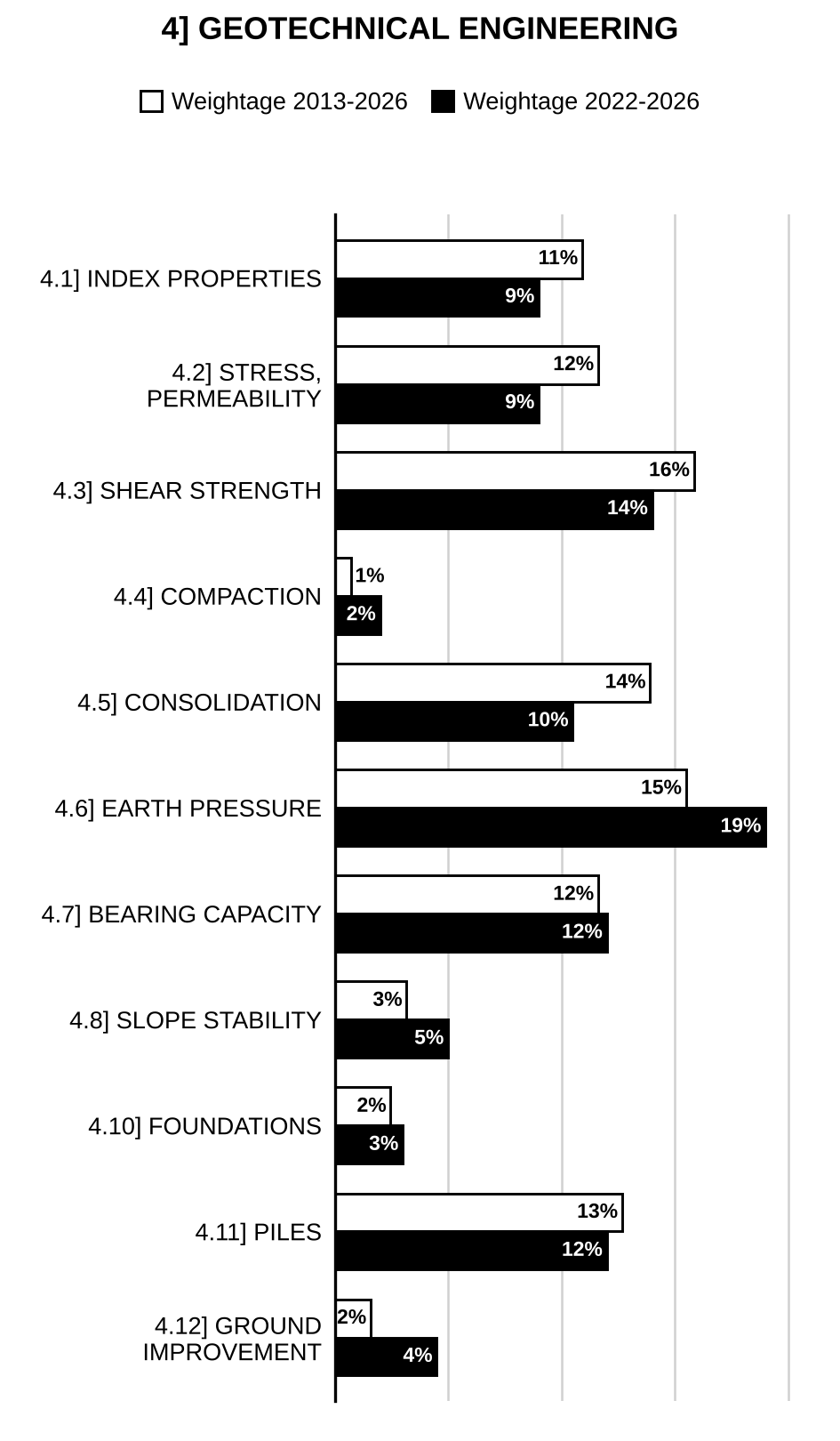
4.1] Soil type, structure and index properties
22 questions
The shrinkage limit test was conducted in a laboratory and the following results were obtained: Initial mass of saturated clay = 45.0 g Final mass of dry clay pat = 31.2 g Initial volume of soil in saturated state = 24.8 cc Final volume of dry clay pat = 16.1 cc Determine the following properties of the soil, if the soil is at water content of 28.5%: (i) Shrinkage limit (ii) Shrinkage ratio (iii) Specific gravity of soil solids (iv) Maximum volumetric shrinkage (v) Linear shrinkage. [2026/10m/5d]
In a laboratory, the liquid limit test by Casagrande’s apparatus is performed and following results are obtained:
| Test No. | 1 | 2 | 3 | 4 |
| Moisture Content (%) | 68 | 58 | 50 | 45 |
| No. of blows | 4 | 9 | 28 | 46 |
The plastic limit of the soil is 27%. Draw the flow curve and find flow index. Also classify the soil. [2025/10m/5d]
A field density test was conducted by core-cutter method and the following data was obtained: Weight of empty core-cutter = 23 N; Weight of soil and core-cutter = 50 N; Dimensions of the core-cutter dia = 90 mm and height = 180 mm; Weight of wet sample for moisture determination = N; Weight of oven dry sample = N; Specific gravity of soil grains = 2.70. Determine its dry density, void ratio and degree of saturation. [2024/10m/5d]
A 3.0 m high sandy fill material was placed loosely at a relative density of 50%. Laboratory studies indicated that the maximum and minimum void ratios of the fill material are 0.90 and 0.52 respectively. Construction specifications required that the fill be compacted to a relative density of 80%. If , determine: (i) Dry unit weight of the fill before and after compaction. (ii) Final height of the fill after compaction. Take . [2023/15m/7a]
A field density test of a soil was performed by digging a small hole in the soil, weighing the extracted soil and measuring the volume of the hole. The soil (moist) weighed 895 g, the volume of the hole was . After drying the sample weighed 779 g. From the dried soil, 400 g was poured into a vessel in a very loose state which occupied a volume of . The same 400 g was then vibrated and tamped to a volume of . Determine the relative density of the field soil. Given: Specific gravity of solids, and unit weight of water, . [2021/10m/1e]
The in situ moisture content of a soil at a borrow area is 14% and its moist unit weight is . The specific gravity of the solids of the soil is 2.7. The soil is to be excavated and transported to a construction site for use in a compacted fill. The finished compacted volume is . If the specifications call for the soil to be compacted to a dry unit weight of at the moisture content of 16%, determine the volume of soil to be borrowed from the borrow site. Also determine the degree of saturation of the soil after compaction and amount of water to be added to the borrow soil to achieve the desired compaction. Assume unit weight of water = . [2020/15m/3a]
A moist soil sample weighs 20.0 kN. The water content of the soil is 10%. The specific gravity of solids, can be assumed as 2.7. With this information, fill in all blanks in the phase diagram. Also determine the void ratio and degree of saturation of the soil sample. Assume unit weight of water, .
[Figure: Three-phase diagram of the soil: a column divided (top to bottom) into Air, Water and Solid. Volumes on the left with blanks to be filled: = ___ (air), = ___ (water), = ___ (solid), = ___ (air + water) and = ___ (total). Weights on the right: = ___ (water), = ___ (solid) and = ___ (total).]
= total volume, = volume of void, = volume of air, = volume of water, = volume of solids, = total weight, = weight of water, = weight of solids. [2019/10m/1e]
During a compaction work, a 1 m thick stratum of soil was compacted to a total of 30 mm via a roller. Initially the void ratio of soil was 0.9, and the water content was 15%. Determine the final void ratio of the compacted stratum. Also determine the dry unit weight of the soil before and after the construction and initial and final degree of saturation of the soil. Assume the specific gravity of the soil particles, and unit weight of water, . [2018/10m/1e]
An undisturbed soil at a borrow pit has a water content 12 per cent, void ratio 0.55 and specific gravity of solids 2.62. The soil from the borrow pit is to be used for the construction of an embankment. The specifications for the embankment require a dry density of with a water content of 18.5 per cent. Calculate the quantity of water in litres which is required to be added to the borrow pit soil per of finished embankment. [2017/10m/1c]
A site with a large areal extent underlain by 10 m thick, horizontal deposit of dry sand over bed rock, initially at a relative density of 50%, was compacted to a final relative density of 80%. The sand was characterised with the maximum and minimum void ratios of 1.0 and 0.5, respectively. Find the surface settlement following compaction. [2016/10m/5e]
Material for an earthfill was available from three different borrow pits/sites. In the compacted state the fill measured at a void ratio of 0.75. The corresponding in-situ void ratio and cost (cost of material and transportation) of the material for three sites are as follows:
| Borrow site | Void ratio | Total cost per cubic meter |
| 1 | 0.8 | Rs. 200 |
| 2 | 1.15 | Rs. 180 |
| 3 | 1.25 | Rs. 175 |
Determine the most economical site for the above earthfill work. [2015/15m/2a]
The consistency limits of a clayey soil are as follows: Liquid limit = 55%; Plastic limit = 25%; Shrinkage limit = 15% If natural moisture content = 30%, determine liquidity index and plasticity index. [2014/10m/1c]
Draw plasticity chart and explain its use. [2014/10m/1d]
A saturated soil sample has water content of 40% and specific gravity of soil grains is 2.7. Determine its void ratio, porosity, saturated and dry unit weight. [2014/10m/5b]
Which law controls the wet analysis? Give assumptions and limitations of the law. [2012/12m/5c]
The dry unit weight of a soil having 15% moisture content is . Find the bulk unit weight , saturated unit weight and submerged unit weight . Assume . [2012/15m/6c]
A partially saturated sample from a borrow pit has a natural moisture content of 15 percent and bulk unit weight of 1.9 g/cc. The specific gravity of solids is 2.70. Determine the degree of saturation and void ratio. What will be the unit weight of the sample on saturation? [2011/12m/5d]
A sample of coarse sand taken from the field was found to have void ratios of 0.87 and 0.52 in its loosest and densest states respectively. The in situ density and water content of the sand were 1.95 g/cc and 23%. Determine the degree of saturation and relative density of the sand in the field, if . [2010/10m/5d]
The moisture content, void ratio and specific gravity of soil solids of a given soil mass are 10.5%, 0.67 and 2.68 respectively. It is required to prepare three triaxial test specimens (diameter 3.75 cm and height 7.5 cm) from this soil mass. Each specimen should have a moisture content of 15% and a dry density of 1.6 g/cc. Determine (i) the quantity of the given soil to be used for this purpose and (ii) the quantity of water to be mixed with it. [2010/30m/6b]
Compute the void ratio of sand in the loosest possible state, considering it to be made up of equal diameter spherical particles. [2009/5m/5d(i)]
A clayey soil with specific gravity of 2.70, has natural moisture content of 16 percent at 70 percent degree of saturation. What will be its water content if after soaking, the degree of saturation becomes 90 percent? [2009/7m/5d(ii)]
A stratum of saturated clay () has an initial water content of 44 percent throughout its depth. After a long dry spell, the water content at the ground surface is 20 percent and at a depth of 3 m, the water content is 44 percent. The water content may be taken to vary linearly with depth. The shrinkage limit of the clay is 28 percent. If the change in height per unit height of the clay () is 80 percent of its change in volume per unit volume (), what is the amount of settlement of the ground surface due to change in water content which occurred? [2004/20m/6a]
4.2] Effective stress, permeability and seepage
18 questions
Excavation is made in a soil whose porosity is 35% and specific gravity of soil grains is 2.65. A 3.0 m layer of this soil is subjected to an upward seepage head of 4.0 m. What factor of safety exists against boiling (piping)? If a factor of safety of 2 is required against boiling, what depth of gravel is required to be placed above the soil stratum? Assume unit weight of gravel and the soil to be the same and loss of head in the layer to be negligible. Assume . [2023/10m/5e]
Plot the variations of (i) total pressure, (ii) neutral stress and (iii) effective stress for a fine sand deposit, having a porosity of 40% and specific gravity of 2.7, extending to a depth of 10 m below the ground surface. The groundwater table is 5 m below the ground surface and the sand is saturated by capillary water up to a height of 1 m above the water table. The degree of saturation of the first 4 m of moist soil below the ground surface is 10%. Take the unit weight of water as . [2022/20m/6b]
Distinguish between discharge velocity and seepage velocity in the case of flow of water through soils. [2022/5m/7a(i)]
A soil sample 90 mm high and in cross-section was subjected to a falling head permeability test. The head fell from 500 mm to 300 mm in 1500 seconds. The permeability of the soil was mm/s. Determine the diameter of the standpipe. [2022/10m/7a(ii)]
A pit is to be excavated in a fine sand stratum completely saturated up to the ground surface. The void ratio of the soil was 0.5 and specific gravity of soil solids is 2.7. The pit is to be dug to a depth of 6.3 m. To stabilise the bottom of the excavation (to prevent sand boiling) it is decided to drive steel sheet piles to act as cut-off walls that encircle the excavation. Determine the minimum depth of sheet piling required for an impending quick condition. Derive the formula, if any, used. Use unit weight of water as . [2020/10m/1e]
At a given site, the soil stratum consists of a thick clay layer. The ground water table is located 2.0 m below the ground surface. Above the ground water table, the degree of saturation of the soil is 90%. If the specific gravity of solids of soil is equal to 2.7 and the void ratio of the soil is 1.0, determine (i) at which depth below the ground surface the vertical effective stress is equal to 100 kPa. (ii) what is the vertical effective stress at the same depth, immediately after the ground water table is lowered further by 2.0 m. Assume unit weight of water, . [2019/15m/3c]
At a given site, an 8 m thick saturated clay is underlain by a sand layer. The natural water content of the clay soil was 30% and the specific gravity of soil particles was 2.7. The sand layer is under artesian pressure equivalent to 3 m of water head. It is proposed to make an excavation in the clay layer. How deep can the excavation be made before the bursting of the clay layer by bottom heave? If a factor of safety of 1.5 is desired, what would be the depth of excavation for the same clay layer? Assume unit weight of water, . [2018/15m/3a]
A foundation trench is to be excavated for a large project in a site. The soil investigation report shows the following details:
| Depth from Ground surface | Type of soil | Index properties |
| 0 – 8 m | Fine sand | Void ratio = 1.20, Sp.gr. = 2.62 |
| 8 – 10 m | Greyish clay | Void ratio = 0.76, Sp.gr. = 2.65 |
| Below 10 m | Coarse sand | — |
It is observed that an open excavation is stable up to 5.75 m depth with the existing water table. The excavation is to be made up to 8.5 m depth for which water table is to be lowered. What are the initial and final depths of water table? [2017/10m/5c]
An excavation is made in a soil whose porosity is 30% and the specific gravity of soil solids = 2.6. A 1.5 m thick layer of this soil is subjected to an upward seepage head of 2.0 m. Find out what factor of safety exists against the piping (boiling). If a factor of safety of 2 is needed against the piping, what depth of gravel is required to be placed above the soil layer? Assume the unit weight of gravel to be the same as that of the soil and negligible loss of head in the gravel layer. [2016/10m/1e]
The details of the subsoil conditions at a site are shown in Figure 2(b) together with the details of the soil properties. The ground water level is 1.2 m below the upper surface of the silt. It can be assumed that the gravel has a degree of saturation of 50% and that the silt layer is fully saturated. Plot the total vertical stress, neutral stress (pore pressure) and effective vertical stress over the entire depth of subsoil up to the rock layer. Also, determine the effective vertical stress at a point 1.0 m above the rock layer.
[Figure: Figure 2(b) – Soil profile from ground surface: Gravel 1.8 m thick (, ); below it Silt (, ) with the water table (W.T.) 1.2 m below the top of the silt and a further 4.0 m of silt below the W.T.; Rock below the silt] [2016/15m/2b]
The ground water movement at a site takes place through a soil zone comprised of 3 m thick sand with coefficient of permeability 0.01 cm/s (in both directions) overlain by 1 m thick fine gravel with coefficient of permeability 0.1 cm/s (in both directions). Determine the coefficient of permeabilities applicable for horizontal and vertical ground water movements through the layer. [2015/10m/1d]
A sand deposit has dry unit weight = and porosity = 45%. Determine critical hydraulic gradient. [2014/10m/5c]
In a variable head permeability test the initial () hydraulic head is 45 cm and it drops 1 cm in 5 minutes. Calculate the time required for the head to drop further by 10 cm i.e. from 44 cm to 34 cm. [2013/10m/5d]
For sub-soil conditions shown in the figure draw total, effective and neutral stress diagram up to a depth of 8 m. Neglect capillary rise. Take .
[Figure: Soil profile below ground level (G.L.): Sand layer 5 m thick, with , ; water table at 3 m below G.L. (3 m of sand above and 2 m of sand below the water table). Below the sand, a Clay layer 3 m thick with , . Total depth shown 8 m.] [2013/15m/6c]
What is quicksand phenomenon? How does it happen and how is it remedied? [2012/12m/5d]
A masonry dam has pervious sand as foundation. Determine the maximum upward gradient, if a factor of safety of 4 is required against boiling. For the sand the porosity, and specific gravity of solids, . [2011/12m/5e]
Find the ratio of horizontal permeability to vertical permeability for a soil deposit consisting of three layers. The second layer has the permeability ten times that of the first layer and the thickness half that of the first layer. The third layer has thickness twice that of the first layer and permeability twice that of the second layer. [2009/10m/7c(i)]
An excavation has to be made in a 10 m deep clay stratum underlain by a bed of sand. In a trial borehole made, the groundwater was found to rise to an elevation of 3.5 m below GL. What is the safe depth of excavation without its bottom becoming unstable due to uplift pressure of groundwater? If the excavation has to be made safely up to a depth of 8 m, what is the depth up to which water table should be lowered in the vicinity of the trench? Take specific gravity of clay as 2.7 and void ratio of clay as 0.7. [2009/10m/7c(ii)]
4.3] Shear strength
18 questions
Consolidated drained tests on clay specimens were performed and the following results were obtained:
| Specimen No. | Confining pressure (kPa) | Axial load (N) | Axial deformation (mm) | Volume change (cc) |
| 1 | 200 | 410 | 11.0 | 7.0 |
| 2 | 400 | 850 | 12.3 | 8.5 |
| 3 | 600 | 1275 | 14.6 | 10.0 |
The initial diameter and length of saturated clay sample were 38 mm and 76 mm respectively. Determine the shear parameters in terms of total stress and effective stress. Also, comment on the results obtained and its application. [2026/15m/8a]
The consolidated undrained (CU) tests were performed on the four over-consolidated clay samples obtained from a site. The pre-consolidation pressure was . The results of triaxial test in CU condition are as follows:
| Test sample | Cell pressure | Deviator stress | Pore pressure | Remark |
| 1 | 100 | 290 | – 40 | All the tests were performed in CU condition. The deviator stress and pore pressure were at failure. |
| 2 | 200 | 430 | – 20 | |
| 3 | 400 | 600 | 50 | |
| 4 | 600 | 840 | 110 |
Determine the effective shear strength parameters. Draw the variation of pore pressure parameter ‘A’ (at failure) with over-consolidation ratio. [2025/15m/8a]
A particular soil failed under a major principal stress of 600 kN/m² with a corresponding minor principal stress of 200 kN/m². If for the same soil, the minor principal stress had been 300 kN/m², determine what the major principal stress would have been if (i) and (ii) . [2024/15m/8b]
The shear stress induced at a depth of 7.0 m due to construction of a nearby foundation is 50 kN/m². The soil properties at the site are given below: Unit weight () = 18 kN/m³; Effective cohesion () = 12 kN/m²; Effective friction angle () = 30°. Compute the factor of safety against shear failure assuming water table located far below the point. Also compute the percentage reduction in factor of safety if water table rises to the ground level. Take unit weight of water = 9.81 kN/m³. [2023/10m/5d]
Laboratory results of a soil have shown that its unconfined compressive strength is . In a triaxial compression test, a specimen of the soil when subjected to a confining pressure of failed at an additional stress of . Estimate the shearing strength of the same soil along a horizontal plane at a depth of 4 m at the site. The groundwater table is at a depth of 2.5 m from the ground level. Take the dry unit weight of the soil as and specific gravity as 2.7. Also, assume the unit weight of water as . [2022/15m/7c]
A sample of dry cohesionless soil whose angle of internal friction is 35°, is subjected to a triaxial test. If the minor principal stress () is 105 kPa, at what values of deviator stress () and major principal stress () will the test specimen fail? [2021/10m/5e]
The subsoil at a site consists of a 12.0 m thick homogeneous layer of dense sand having dry unit weight, , and . The natural ground water level lies at 2.5 m below the ground surface. Assume that the soil is dry above the water table and unit weight of water, . Determine the shear strength of the soil along a horizontal plane through the middle of the sand layer. [2021/15m/7a]
A cohesionless soil specimen in a triaxial test is subjected to a major and minor principal stress and respectively. Draw Mohr’s circle and derive an expression for in terms of and . Also derive the expressions for shear stress, and normal stress, on the failure plane in terms of , and . [2020/10m/7a]
Explain the conditions when vane shear test is suitable for determining the shear strength of the soil. Derive an expression for shear strength of soil in terms of applied torque and vane dimensions considering shearing at top, bottom and surrounding soil. An in situ vane shear test was conducted in a clay soil at the bottom of a borehole. A torque of 150 N-m was required to shear the soil. What was the undrained shear strength of clay neglecting shearing resistance at the top? The vane was 100 mm in diameter and 150 mm long. [2020/15m/8a]
A dry sand specimen (cohesion = 0) is put through a drained triaxial test. For a cell pressure of 100 kPa, the sample failed at a deviator stress of 350 kPa. Determine the angle of internal friction, of the sand specimen from the given test data. Also determine the deviator stress at failure for the same soil sample when cell pressure applied is 200 kPa. [2019/10m/5e]
A sample of dry cohesionless soil is subjected to a triaxial test. From another test on a sample of same soil, the angle of internal friction of the soil was estimated as 40°. If the minor principal stress of 100 kPa is applied on the sample during the test, at what values of deviator stress () and major principal stress will the test specimen fail? [2018/15m/6c]
In a consolidated drained triaxial test (CD test) a specimen of saturated sand failed under a deviator stress of 220 kPa when the cell pressure was 100 kPa. Determine the shear strength parameters, the shear strength and the maximum shear stress. [2017/15m/3a]
The following results were obtained from a series of consolidated undrained triaxial tests on specimens of saturated clay. Determine the shear strength parameters (both effective stress and total stress) of the soil.
| (kPa) | at peak (kPa) | u at peak (kPa) |
| 100 | 137 | 28 |
| 200 | 210 | 86 |
| 300 | 283 | 147 |
[2016/20m/4c]
An in-situ vane shear test was conducted at the bottom of a borehole in a soft clayey soil. A torque of 155 N-m was required to shear the soil. The vane was 100 mm diameter and 150 mm long. What was the undrained shear strength, Cu of the soil? Derive the relevant expression relating to torque vane dimension, and undrained shear strength of the soil. [2015/15m/4b]
An embankment is being built of a soil whose effective stress shear strength parameters are as follows: ; degrees; Unit weight = The pore pressure parameters and determined by the triaxial shear tests are 0.6 and 0.8, respectively. The height of the embankment has just been raised from 5 m to 8 m. Determine the shear strength of the soil at the base of the embankment. Assume that the dissipation of pore pressure during this stage of construction is negligible and the lateral pressure at any point is one-half of the vertical pressure. [2014/20m/2b]
In unconfined compression test, a soil sample fails at stress. The failure plane makes an angle of 50° with the horizontal. Calculate the values of cohesion and angle of internal friction of the soil. [2013/10m/5e]
What are the shear strength parameters? How are they determined? The following data are obtained from a series of drained shear box tests on sample of silty clay. Plot the graph for effective shear strength parameters. Give the value of attraction (Janbu):
| Normal stress () | 20 | 40 | 60 |
| Maximum shear stress () | 19.5 | 28.6 | 38.0 |
[2012/15m/6d]
(i) A loading of is acting on an annular foundation of width 5 m and inside diameter of 10 m. Find the vertical stress intensity at a depth of 10 m below the centre of the foundation. (ii) In a direct shear test on clean dry sand, failure occurred at a shear stress of when the normal stress was . Draw the Mohr’s stress circle and find the angle of internal friction. Determine the magnitudes of principal stresses and the orientation of principal planes with respect to plane of shearing. [2004/20m/6b]
4.4] Compaction
2 questions
Soil from a particular site yields a maximum dry unit weight of at an optimum moisture content of 16% during a standard Proctor test. If the value of is 2.65, what is the degree of saturation? What is the maximum dry unit weight, it can be further compacted to? Take the unit weight of water as . [2022/10m/5b]
During a compaction test a soil attains the maximum dry density of at a water content of 15 percent. The specific gravity of soil is 2.7. Determine the degree of saturation, air content and percentage of air voids at the maximum dry density. What would be the maximum theoretical dry density corresponding to zero air voids at optimum water content. [2004/12m/5d]
4.5] Compressibility and consolidation
22 questions
The data with respect to a normally consolidated clay are as follows: Thickness of the clay layer = 3.0 m Initial void ratio = 0.75 Liquid limit = 50% Effective overburden pressure on the clay layer = Increment of effective pressure on the clay layer = Secondary compression index, Time for completion of primary settlement = 2.0 years What will be the consolidation settlement of the clay layer, six years after the completion of primary consolidation settlement? [2026/15m/7a]
A 5 m thick clay layer is subjected to drained condition both at top and bottom. It has few sand drains in square pattern. The spacing of sand drains are 3 m centre to centre. The coefficient of consolidation in vertical and radial directions are same and equal to . The radius of the sand drains is 0.25 m. Assuming that there is no smear at the periphery of drain wells, it has been estimated that a given uniform surcharge would cause a total consolidation settlement of 200 mm without sand drains. Find the consolidation settlement of clay layer with same surcharge and sand drains, at times of 6 months, 9 months and one year. Draw the variation of settlement with time. [2025/15m/7b]
The soil profile at a building site consists of dense sand up to 3 m depth, normally loaded soft clay from 3 m to 8 m depth and stiff impervious rock below 8 m depth. The ground water table is at 0.60 m depth below ground level. The sand has a density of 18.6 kN/m³ above water table and 19.2 kN/m³ below water table. For the clay, natural water content is 50%, liquid limit is 70% and specific gravity is 2.70. Calculate the probable ultimate settlement resulting from a uniformly distributed surface load of 50 kN/m² applied over an extensive area of the site. [2024/15m/7b]
At a site, fine sand exists to a depth of 10 m and below this lies a soft clay layer 7.0 m thick. Water table is 4.0 m below the ground surface. Saturated unit weight of sand is 20.0 kN/m³ and the wet unit weight above the water table is 18 kN/m³. The water content of the normally consolidated clay is 42%, liquid limit is 46% and the specific gravity of the solid particles is 2.75. The proposed construction will transmit a net stress of 130 kN/m² at the centre of the clay layer. Find the average settlement of the clay layer. [2023/15m/8a]
The figure below represents time and consolidation relationship for a clay sample 30 mm thick subjected to a given pressure range under double drainage condition. Determine: (i) The coefficient of consolidation () for the sample. (ii) The time required for 75% consolidation of the same clay soil, if it were 2 m thick with similar drainage condition. (iii) The time required for same degree of consolidation with single drainage condition. Given:
[Figure: Square-root-of-time fitting plot on a grid. Horizontal axis: (), marked 0 to 9. Left vertical axis: Strain (increasing downwards); right vertical axis: Percent consolidation, 0 at top to 100 at bottom in steps of 10. The laboratory curve starts at the origin, is nearly straight at first and flattens at large times. An initial straight-line tangent and a second line with abscissae 1.15 times larger are drawn from the origin. Two construction dimensions are marked from the vertical axis: b (to the initial tangent) and 1.15 b (to the second line) at the level of about 60% consolidation, b ending at about and 1.15 b at about 4.1; and a and 1.15 a at a lower level (below 90%), a ending at about and 1.15 a at about 7.4. The 1.15 line cuts the curve at 90% consolidation at –7.5 (values read from the graph; no numbers are printed for a, b or ).] [2021/15m/3a]
Two footings are placed at a depth of 1.0 m on a sand layer as shown in the figure below. The footing at the left is of size 2 m × 2 m and that at the right 1.5 m × 1.5 m and carry loads of 400 kN and 225 kN, respectively. The location of water table and other relevant soil properties are shown in the figure. If the settlement of the footing is considered only because of the consolidation of compressible clay layer (ignoring elastic settlement of sand and clay), where do you expect the maximum settlement? Justify your answer. Also determine the maximum consolidation settlement for the footing soil condition shown in the figure. Assume unit weight of water as . Assume 2.0 vertical 1.0 horizontal dispersion of footing pressure over depth.
[Figure: Two column footings at a depth of 1 m below ground level, centre-to-centre 2 m apart: left footing 2 m × 2 m carrying 400 kN, right footing 1.5 m × 1.5 m carrying 225 kN. Sand layer, , from the ground surface down to the water table (WT) at 2 m below ground level (i.e. 1 m below the footing base). Below the WT a compressible clay layer 3 m thick: , , ; underlain by sand and gravel.] [2020/20m/4c]
The compression curve for a certain clay soil is a straight line on the semi-logarithmic plot and it passes through the points , kPa and , kPa. Write the generalised equation of change in void ratio, for the soil. Also determine the change in void when the pressure on the soil increased from 100 kPa to 400 kPa. [2019/10m/5d]
A 15 m long and 10 m wide raft is placed on a 16 m thick clay deposit, consisting of 4 sub-layers as shown in the figure below. Determine the settlement of the raft foundation because of the consolidation of the clay layers. Assume unit weight of water, .
[Figure: Soil profile: raft carrying 100 kPa placed with its base 2 m below the ground surface; water table (WT) at the level of the raft base (2 m below ground). Top 2 m: . Below the WT, four clay sub-layers each 4 m thick: (1) , , ; (2) , , ; (3) , , ; (4) , , ; the base of the fourth layer (16 m below the raft base) is drawn with a gravel/stone symbol.] [2019/15m/6c]
A square footing of size 3 m × 3 m is placed on a sand and gravel layer at a depth of 1.5 m from the ground surface. Below the sand and gravel layer, a layer of normally consolidated soil of thickness 3 m is present. Details of soil properties and the footing loading are shown in the figure. Determine the total expected consolidation settlement for the clay layer because of the footing loading.
[Figure: Square footing 3 m wide with its base 1.5 m below ground level, carrying a column load Q = 1100 kN. Soil above the footing base (0–1.5 m): ; water table (WT) at 1.5 m depth (footing base level). Sand and gravel, 4.5 m thick below the WT (1.5–6.0 m): . Normally consolidated clay, 3.0 m thick (6.0–9.0 m): , , .] [2018/15m/8c]
A light weight building stands over a 10 m thick stratum of sand. Beneath the sand stratum a clay layer of 5 m thick exists. The clay layer is underlain by a rock stratum. The water table lies at a depth of 1.0 m below ground surface and the sand above the water table is saturated with capillary rise. The sand has a void ratio of 0.75 and sp. gr. 2.65. During dry season, water is pumped out from the sand stratum till the water table is lowered by 4.0 m and sand above water table becomes dry. Calculate the number of days when the building settles by 25 mm. Ignore settlement during pumping operation. Take properties of clay: Void ratio = 0.60, Sp. gr. = 2.70, Liquid limit = 40%, Coefficient of consolidation = . [2017/15m/2b]
The coordinates of two points on the virgin compression line are as below: kPa, ; kPa, . In the field, a 3 m thick normally consolidated layer of this soil subjected to construction load and the average effective vertical stress increased from 250 kPa to 450 kPa. Determine (i) the compression index and initial void ratio of the clay layer, (ii) the consolidation settlement of the layer, and (iii) the load increment to cause 25 mm final consolidation settlement to occur and the corresponding void ratio. [2016/20m/7c]
What is the preconsolidation pressure? Describe a method to determine the preconsolidation pressure. [2015/15m/4a]
Differentiate between the following: (i) Compaction and Consolidation (ii) Pore water pressure and Seepage pressure (iii) Liquidity index and Relative consistency (iv) Shallow foundation and Deep foundation. [2014/10m/5e]
A normally consolidated clay has a compression index = 0.2. Initial void ratio of this clay layer is 0.9 and thickness = 3 m. If the initial soil stress is , how high can the stress become before the ultimate settlement is 2 cm? [2013/15m/8c]
In laboratory test on a clay sample of thickness 25 mm drained at top only, 50% consolidation occurred in 11 minutes. Find the time required for the corresponding clay layer in field, 2 m thick and drained at top only, to undergo 70% consolidation. Assume and . [2012/15m/7c]
A strata of normally consolidated clay of thickness 3 m is drained on one side only. It has a hydraulic conductivity of cm/s and coefficient of volume compressibility . Determine the ultimate value of the compression of the stratum assuming a uniformly distributed load of and also determine the time required for 20 percent consolidation. [2011/20m/6b(i)]
How is consolidation different from compaction? What do you understand by the terms – immediate settlement, primary consolidation and secondary consolidation? [2011/10m/6b(ii)]
A raft foundation is to be constructed on a 7.5 m thick clay layer sandwiched between two sand layers. In order to predict the time rate of settlement of the building, a consolidation test was conducted in the laboratory on a 2.5 cm thick undisturbed sample of the soil by keeping porous stones both at the top and bottom. The sample was found to have undergone 50% consolidation in 12.5 minutes. Determine the time required for realising 50% settlement of the building. [2010/10m/5e]
The coefficient of consolidation () of a clay was found to be . The final consolidation settlement for a 5 m thick layer of this clay was calculated as 280 mm. Assuming a uniform initial excess pore-water pressure distribution and permeable layer to be present both above and below the clay layer, compute the settlement time for– (i) 90 percent primary consolidation (take for ); (ii) settlement of 100 mm. [2009/12m/5e]
What do we obtain from a consolidation test? List the parameters we obtain. Describe how one can use these parameters in the design. [2009/12m/8c(i)]
In a consolidation test, a specimen whose void ratio was 1.068 under effective pressure of changed to 0.994 when effective pressure was increased to . Compute the coefficient of compressibility, compression index and coefficient of volume compressibility. [2009/8m/8c(ii)]
A settlement analysis carried out for a proposed structure indicates that 5 cm of settlement will occur in 5 years and that the final settlement will be 25 cm. The computation was made on the basis of double drainage condition. However, subsequent borings established only single drainage condition. Calculate the final settlement and the settlement in 5 years for the changed condition. [2004/12m/5f]
4.6] Earth pressure
22 questions
A retaining wall 5 m high with a smooth vertical back is pushed against a soil mass. What is the total passive pressure, if the horizontal soil surface carries a uniform load of ? Also, determine the location of resultant thrust, where it is acting. The properties of the soil are as follows: Effective cohesion = 35 kPa Effective angle of shearing resistance = 20° Bulk density = [2026/10m/6c(i)]
In the given diagram, the height of a retaining wall is 5 m with a batter angle 6°. The back face of the retaining wall is supporting a sandy soil, the surface of which is sloping at an angle 12° with the horizontal. Determine the active force per unit length of the retaining wall. Also find the direction and location of the resultant force. The properties of backfill soil are as below: Angle of shearing resistance = 32° Cohesion = 0 Assume angle of wall friction as 50% of angle of shearing resistance. Bulk density =
[Figure: Retaining wall of trapezoidal section, height 5 m; vertical front (left) face; back (right) face inclined at 6° to the vertical, the wall widening towards the base; backfill surface rising from the top of the back face at 12° to the horizontal.] [2025/15m/6c(i)]
What is the effect of earthquake on lateral earth pressure against a retaining wall? [2025/5m/6c(ii)]
A braced cut 7.0 m deep and 3.0 m wide is proposed in a cohesionless sand deposit. Assume that the first row of struts to be located at 0.5 m below ground level and the spacing of strut as 2.5 m as shown in the diagram. In the plan, the struts are placed at spacing of 2 m centre to centre. Using Peck’s empirical relation for pressure diagram, determine the design loads in the struts. The properties of sand are as follows: Angle of shearing resistance = 30° Bulk density =
[Figure: Section of the braced cut, 3.0 m wide and 7.0 m deep; strut A at 0.5 m below ground level, strut B 2.5 m below A, strut C 2.5 m below B; 1.5 m from C to the bottom of the cut.] [2025/15m/7a]
A retaining wall 8 m high, with a smooth vertical back is pushed against a soil mass having , and unit weight 18 kN/m³. It carries a surcharge of 40 kN/m² uniformly on its top surface. Draw the passive pressure distribution diagram and find the point of application of the resultant thrust. [2024/15m/8a]
A retaining wall is shown in the figure below: Assuming that the wall can yield sufficiently, determine the Rankine active force per unit length of the wall and also determine the location of the resultant line of action.
[Figure: Vertical retaining wall 7 m high retaining horizontal backfill (depth z measured downward from the top). Layer ①: top 3 m, , , . Ground water table at 3 m depth (top of layer ②). Layer ②: next 4 m, , , .] [2023/20m/6c]
A vertical cut, 4.5 m deep, is to be made in a – soil having cohesion = , angle of internal friction = 16° and unit weight = . Compute the following: (i) The active earth pressure at the top and bottom of the cut (ii) The depth up to which the tension cracks develop (iii) The maximum depth of excavation that can be left unsupported. [2022/15m/8a]
Investigate the stability against overturning, sliding resistance and foundation soil pressure of the retaining wall shown in the figure. The retaining wall is to support a deposit of granular soil which has unit weight, and angle of internal friction, . The coefficient of base friction is 0.5. Allowable soil pressure for the foundation soil is 150 kPa. Use Rankine’s theory to calculate the active earth pressure on the wall and neglect passive pressure from the toe side. Given: Unit weight of concrete, .
[Figure: Trapezoidal concrete gravity retaining wall (), height 6 m, top width 1 m, base width 3 m; the back face (retaining the soil, on the right) is vertical and the front face (left) is inclined. Granular backfill on the right, level with the top of the wall: , , C = 0.] [2021/20m/4c]
An unsupported cut is made at a site as shown in the figure below. Determine: (i) Lateral stress at the top and bottom of the cut. (ii) The maximum depth of potential tension crack. (iii) The maximum depth of unsupported cut possible at the site. (iv) If the soil is excavated upto 8 m depth and supported by a vertical earth retaining wall, total active thrust on the wall.
[Figure: Vertical unsupported cut 4 m deep; soil: , , .] [2020/10m/5e]
The earth retaining wall shown in the figure is to support a backfill of granular soil, which has unit weight of and angle of internal friction of 40°. The wall also supports a surcharge of as shown in the figure. The coefficient of base friction is 0.5. Determine the factor of safety against sliding and overturning for the wall. Also determine the maximum and minimum vertical pressure below the base of the retaining wall.
[Figure: Trapezoidal gravity retaining wall of height 6.0 m, top width 1.2 m, base width 3.3 m; back face (towards the backfill, right) vertical, front face (left) inclined; unit weight of wall . Backfill level with the top of the wall: , , carrying a uniform surcharge of . Ground level in front of the wall at the level of the base.] [2019/20m/8a]
A rigid retaining wall of height 6 m retains a dry cohesionless levelled backfill with angle of internal friction, and unit weight, . A support is to be provided behind the wall to prevent from yielding of wall. Determine the force on the support if used to prevent yielding of wall for a unit length of wall. Also, determine the point of application of the support from the base of the wall. [2018/10m/5e]
The above figure shows a two-layered backfill behind a 9.0 m high retaining wall with a smooth vertical back. Draw the total active earth pressure distribution diagram and find the point of application of the resultant earth pressure.
[Figure: Backfill profile below ground level (G.L.): Layer I, 5 m thick, with the water table inside it (water-table symbol drawn about 2 m below G.L.; its depth is not dimensioned); soil above the water table , , ; Layer I below the water table , , . Layer II, 4 m thick: , , .] [2017/20m/4a]
An anchored sheetpile founded in a cohesive soil is to retain a sandy backfill as shown in the above figure. Calculate the depth of embedment of the sheet pile and the pull in the anchor.
[Figure: Anchored sheet pile wall retaining sand on the right side; the anchor (horizontal tie) is 1.0 m below the top of the backfill. Sand above the water table: , , ; water table 2.0 m below the top, at the same level on both sides of the pile (water on the left side); sand below the water table: , , , extending 3.0 m below the water table to the clay surface (dredge level on the left = top of clay, 5.0 m below the top of the backfill). Below: CLAY, , , , into which the sheet pile is embedded.] [2017/15m/7b]
For the earth retaining structure shown in the figure, determine the total active thrust on the wall, and the point of application of the thrust above the base of the wall. Given H = 5 m, , C = 0, , m, , (above water table), .
[Figure: Vertical wall of height H = 5 m with vertical back face () retaining horizontal backfill (, C = 0); uniform surcharge q = 250 on the backfill surface; water table at m above the base of the wall; above the water table, below it] [2015/15m/8a]
A masonry retaining wall has to retain sand with a unit weight of . Angle of internal friction 30°. Assume sand to be dry and the height retained is 4.2 m. The top width of the wall is 300 mm. Bottom width is 2100 mm. Check whether the resultant of the forces is within the middle third of the base. Calculate the stability factors of the wall. The back of the wall adjoining the soil is vertical. The top level of sand is horizontal. Unit of weight of masonry is . [2013/15m/6b]
What is earth pressure at rest? Explain it considering active and passive pressure. [2012/12m/5e]
Explain clearly the difference between the active earth pressure and passive earth pressure. Give two examples of each state. [2011/10m/7b(i)]
A retaining wall 6 m high, with a smooth vertical back is pushed against a soil mass having , and . What is the total Rankine pressure if the horizontal soil surface carries a uniformly distributed load of ? What is the point of application of resultant thrust? [2011/20m/7b(ii)]
A retaining wall with a smooth vertical backface has to retain a backfill of soil up to 5 m above GL. The surface of the backfill is horizontal and it has the following properties: , , (i) Plot the distribution of active earth pressure on the wall. (ii) Determine the depth of the zone of tension cracks. (iii) Determine the magnitude and point of application of active thrust. (iv) Determine the intensity of a fictitious uniform surcharge which, if placed over the backfill, can prevent the formation of tension cracks. (v) Compute the resultant active thrust after placing the surcharge. [2010/30m/7b]
A 5 m high smooth retaining wall with vertical face retains a cohesive backfill having unconfined compressive strength of , and . Calculate the depth of tension crack and the total active earth pressure, assuming the tension crack has fully developed. The backfill surface is horizontal. [2009/12m/5f]
(i) Differentiate between ‘state of elastic equilibrium’ and ‘state of plastic equilibrium’ of soil mass. Show them by drawing Mohr’s circle and envelope. Show the state of equilibrium for active, passive and at rest conditions. What will be the active and passive pressures in a fluid with density at a depth of 2 m? (ii) A cut 10 m deep is excavated in sand ( and ) and is to be braced by sheeting and bracing system. The top strut will be at 0.5 m below G.L. followed by subsequent struts at every 1.5 m centre to centre in vertical direction. The spacing of struts along the cut is 3 m centre to centre. Compute the top, middle and bottom strut loads. [2004/20m/7b]
A trapezoidal masonry retaining wall 6 m high and 1.2 m wide at top retains earth of unit weight , to the top of the wall on the vertical face. Calculate the minimum bottom width necessary so that no tension occurs at the base. Density of masonry: . [2004/20m/8b]

Preparing for Prelims too?
Our UPSC Prelims Topic-wise PYQ eBook covers every Prelims question with detailed explanations, so you can see exactly where UPSC asks from.
View the BookDownload Free Sample4.7] Bearing capacity and settlement
18 questions
The unconfined compressive strength of a saturated clay is . Determine the net ultimate bearing capacity of a square footing of side 0.75 m, resting on the surface of the saturated clay. What will be the safe bearing capacity if factor of safety is 2.5? [2025/10m/5e]
Two plate load tests were conducted at a site – one with a 300 mm square plate and other with a 600 mm square test plate. For a settlement of 25 mm the loads were found to be 21.6 kN and 64.8 kN respectively in the two tests. Determine the allowable bearing pressure of the sand and the load which a square footing 1.5 m × 1.5 m can carry with the settlement not exceeding 25 mm. [2024/10m/5e]
A strip footing of width 2.8 m as shown in the figure is founded at a depth of 2.5 m below the ground surface in a soil. Water table is at a depth of 6 m below the ground surface. The average moist weight of soil above the water table is 18 kN/m³. Determine the ultimate bearing capacity, net ultimate bearing capacity, net allowable bearing pressure and the load/m for a factor of safety of 2.5. Use the general shear failure theory of Terzaghi. Given: For , , , . What will be the percent decrease in ultimate bearing capacity if during the flooding, water level rises 2 m above around surface?
[Figure: Strip footing of width B = 2.8 m with its base 2.5 m below the ground surface; water table 6 m below the ground surface. Soil: , , .] [2023/15m/8b]
A square footing is founded at a depth of 0.8 m in a homogeneous bed of sand having a unit weight of and an angle of shearing resistance of 38°. Assuming the water table to be at a great depth, compute the safe load that can be carried by the footing. Use Terzaghi’s theory and assume a factor of safety of 3. For , take and . [2022/10m/5e]
The following data was obtained from a plate load test carried out on a 60 cm square test plate at a depth of 2 m below the ground surface on a sandy soil with water table at a great depth:
| Load intensity () | 0 | 50 | 100 | 150 | 200 | 250 | 300 |
| Settlement (mm) | 0 | 2.0 | 4.0 | 7.5 | 11.0 | 16.3 | 23.5 |
Determine the settlement of a square footing founded at a depth of 2 m below the ground surface, carrying a load of 1100 kN, and compare this settlement with the permissible settlement specified by the Indian Standards. [2022/15m/8c]
A 2 m × 2 m square footing is placed at 1.8 m below the ground surface. The ground water table is at the ground level. The subsoil consists of a uniform deposit of soft, loose soil. The laboratory test results of the soil are as follows: Angle of internal friction, Cohesion, C = 15 kPa Unit weight of soil, Determine the allowable load that can be imposed on this square footing with a factor of safety of 3. Given:
| 10 | 8.34 | 2.47 | 0.37 |
| 12 | 9.28 | 2.97 | 0.60 |
| 14 | 10.37 | 3.59 | 0.92 |
| 16 | 11.63 | 4.34 | 1.37 |
| 18 | 13.10 | 5.26 | 2.00 |
| 20 | 14.83 | 6.40 | 2.87 |
| 22 | 16.88 | 7.82 | 4.07 |
| 24 | 19.32 | 9.60 | 5.72 |
[2021/15m/7b]
A square footing 0.3 m × 0.3 m is placed on the surface of dense cohesionless sand with unit weight and subjected to a load test. If the footing fails at a load of 47.5 kN, what is the value of for the sand? The table given below may be used. If a footing of size 1.5 m × 1.5 m is proposed on the same soil with a depth of foundation 1.0 m, what will be the allowable capacity of the footing with a factor of safety of 2.5? In all cases water table was at a great depth and its effect is to be ignored.
| 18 | 13.10 | 5.26 | 2.00 |
| 20 | 14.83 | 6.40 | 2.87 |
| 22 | 16.88 | 7.82 | 4.07 |
| 24 | 19.32 | 9.60 | 5.72 |
| 26 | 22.25 | 11.85 | 8.00 |
| 28 | 25.80 | 14.72 | 11.19 |
| 30 | 30.14 | 18.40 | 15.67 |
| 32 | 35.49 | 23.18 | 22.02 |
| 34 | 42.16 | 29.44 | 31.15 |
| 36 | 50.59 | 37.75 | 44.43 |
| 38 | 61.35 | 48.93 | 64.08 |
| 40 | 75.32 | 64.20 | 93.69 |
[2020/15m/7b]
A strip footing of width 2.5 m is to be constructed on a thick deposit of uniform cohesionless soil. The saturated and dry unit weight of soil are and , respectively. The angle of internal friction of the soil is 35° and the depth of the footing, is 1.5 m. Also for given , and . (i) Assuming the water table at a great depth for which the effect of water table on the bearing capacity can be neglected, determine the allowable bearing capacity of the footing as per Terzaghi’s bearing capacity theory with a factor of safety of 3.0. (ii) Determine the allowable bearing capacity for the same footing with same F.S., when the water table rises to the base of the footing. (iii) Also determine the allowable bearing capacity of the same footing with same F.S., if it is placed on the ground surface and water table is also on the ground surface. Assume unit weight of water, . [2019/15m/4b]
A square footing rests on a uniform thick deposit of stiff clay with an unconfined compressive strength of 120 kPa. The footing is located at 1.2 m below the ground surface and is to carry a total load of 1000 kN. The unit weight of clay soil is and ground water level is at a great depth and its effect can be ignored. Determine the dimension of square footing required for the loading and soil conditions given with a factor of safety of 3. What would be the diameter of the footing if a circular footing is used instead of square footing at the same depth? [2018/15m/4b]
A square foundation has to be constructed on a thick deposit of uniform cohesionless soil with angle of internal friction, . The depth of foundation is 1.2 m. The water table is at a great depth and its effect can be neglected. The allowable design load of the footing with a factor of safety of 3 is 700 kN. Determine the size of the foundation. Given , , and and unit weight of soil, . [2016/15m/2c]
A rectangular footing 4 m × 2 m in plan, transmits a pressure of on a cohesive soil having and . Determine the immediate settlement of the footing at the centre, assuming it to be (i) a flexible footing and (ii) a rigid footing. Take influence factor for flexible footing and 1.20 for rigid footing, respectively. [2014/20m/4c]
What will be the gross and net safe bearing pressure of sand having and effective unit weight of under (i) 1 m wide strip footing (ii) a square footing of 1 m size? Assume the footings are placed at a depth of 1 m below ground surface and the water table is at a great depth. Also, assume a factor of safety of 3.0. Use Terzaghi’s theory. Given , and . [2013/10m/5c]
Using Terzaghi’s theory, determine the ultimate bearing capacity of a strip footing 1.5 m wide resting on a saturated clay (, and ) at a depth of 2 m below the ground level. The water table is also at a depth of 2 m from the ground level. If the water table rises by 1 m, calculate the percentage reduction in the ultimate bearing capacity. [2012/15m/7d]
What is a “standard penetration test”? How is the data obtained from the standard penetration test utilized in foundation design? [2011/10m/8b(ii)]
A 2 m wide strip footing is founded at a depth of 1.5 m below the ground level in a homogeneous bed of sand having unit weight = and angle of internal friction . Using Terzaghi’s theory, determine the safe bearing capacity of the footing. The water table is at 1 m below the ground surface and for , , and . [2010/10m/5f]
State the limitations of plate load test used for finding the bearing capacity of soil. [2009/5m/6c(i)]
A circular footing of 3 m diameter has to carry a gross load of 4500 kN. The foundation soil is clayey sand having , and . Find the depth at which the footing should be placed for factor of safety of 2.5. For – , , [2009/15m/6c(ii)]
(i) What is SPT? How is the SPT value obtained and corrected? (ii) What will be the safe load carrying capacity for a strip footing 2 m wide with a factor of safety of 3? The footing is located in a cohesive soil with and at a depth of 1.5 m below G.L. The soil has specific gravity of 2.7 and void ratio of 0.7. Take water table at ground surface and the bearing capacity factors for as , and . [2004/20m/7a]
4.8] Stability of slopes
5 questions
Discuss the effect of earthquake forces on the stability of earth dams. [2026/10m/6c(ii)]
A canal is to be excavated through a soil with , , and . The side slope is 1 in 1. The depth of the canal is to be 8 m. Determine the factor of safety with respect to cohesion when the canal runs full. What will be the factor of safety if the canal is rapidly emptied? For , the stability number for various values are as given above.
| (in degrees) | 5° | 10° | 15° | 20° | 25° |
| SN | 0.14 | 0.12 | 0.10 | 0.08 | 0.06 |
[2024/15m/7a]
An infinite natural slope with angle of slope 15° (inclination measured from horizontal) has a saturated unit weight of 18 and an effective angle of internal friction, . Determine the factor of safety against failure of the slope (i) when the slope is completely dry or submerged but without seepage, (ii) when seepage occurs at and parallel to the surface of the slope. [2015/10m/5d]
An excavation is made with a vertical face in a clayey soil which has , . Determine the maximum depth of excavation so that it is stable. The stability number, corresponding to and degrees, may be taken as 0.261. Assume FS as 1.0. [2014/10m/2c]
A canal 6 m deep runs through a soil having , , and . The angle of slope of a bank is 45°. Determine the factor of safety with respect to cohesion when the canal is full upto the top of the banks. If the sudden drawdown takes place upto the bed level of the canal, what will be the factor of safety? For = angle of slope of bank = 45°; Stability number = 0.108 Stability number = 0.137. [2004/12m/5e]
4.9] Subsurface exploration
3 questions
What is standard penetration test? What corrections are applied for the test? Name the other penetration tests giving the positive features of the tests. [2012/15m/8c]
What is a “standard penetration test”? How is the data obtained from the standard penetration test utilized in foundation design? [2011/10m/8b(ii)]
(i) What is SPT? How is the SPT value obtained and corrected? (ii) What will be the safe load carrying capacity for a strip footing 2 m wide with a factor of safety of 3? The footing is located in a cohesive soil with and at a depth of 1.5 m below G.L. The soil has specific gravity of 2.7 and void ratio of 0.7. Take water table at ground surface and the bearing capacity factors for as , and . [2004/20m/7a]
4.10] Foundations: types, selection and design
5 questions
The plan of a foundation is shown in the figure. The uniform load intensity on the soil is . Determine the vertical stress increment at a depth 4 m below the point O, using Boussinesq’s method:
[Figure: Plan of the foundation: rectangle ABCD, AB = DC = 8 m, AD = BC = 4 m, with a semicircle of radius 2 m attached outside along side BC; O is the mid-point of BC (centre of the semicircle), 2 m from B and 2 m from C.] [2026/15m/7b]
Differentiate between the following: (i) Compaction and Consolidation (ii) Pore water pressure and Seepage pressure (iii) Liquidity index and Relative consistency (iv) Shallow foundation and Deep foundation. [2014/10m/5e]
A point load of 200 kN acts on the surface of a homogenous soil mass of large extent. Find the stress intensity (i) at a depth of 10 m directly under the load. (ii) at a horizontal distance of 5 m and depth of 10 m. Use Boussinesq equation. [2013/15m/7c]
What type of foundations be provided for successful performance of constructed low-rise structure on expansive soil? [2012/15m/8d]
(i) A loading of is acting on an annular foundation of width 5 m and inside diameter of 10 m. Find the vertical stress intensity at a depth of 10 m below the centre of the foundation. (ii) In a direct shear test on clean dry sand, failure occurred at a shear stress of when the normal stress was . Draw the Mohr’s stress circle and find the angle of internal friction. Determine the magnitudes of principal stresses and the orientation of principal planes with respect to plane of shearing. [2004/20m/6b]
4.11] Pile foundations
17 questions
An RCC pile of 15 m overall length is driven into a deep stratum of soft clay with unconfined compressive strength of 40 kPa. The diameter of the pile is 300 mm. Determine the safe load which can be carried by the pile. Assume factor of safety as 2.5 and adhesion factor as 0.85. If the weight of the pile is 27 kN, what will be the ultimate uplift capacity under undrained condition? Assume coefficient as 0.7. [2026/10m/5e]
A 250 mm diameter concrete pile 8 m long was driven by a double-acting hammer. The driving was carried out by a short dolly and cushion. The average penetration recorded in the last five blows was 3.0 mm per blow. Determine the safe pile load. As per IS 2911 (Part I) – 1979, the coefficient of restitution of the materials under impact for double-acting hammer striking on steel anvil and driving RCC pile is 0.5. The rated energy of hammer is 16.5 kJ and mass of hammer is 22 kN. Assume that only 90% of the rated energy is consumed. The density of RCC pile may be considered as . Assume the factor of safety as 2.5. [2025/15m/8b]
A group of nine friction piles is driven through 5 m of clay with unconfined compressive strength of 60 kN/m² followed by 10 m of clay with unconfined compressive strength of 100 kN/m². The piles are in 3 rows and will be 1.00 m centres in a row and the rows will be 750 mm on centres. Each pile has a diameter of 300 mm. If a factor of safety of 2.5 is required, determine the maximum load that can be carried by the group. Take and unit weight of clay as 16.4 kN/m³. [2024/20m/6c]
A group of 9 driven cast in situ piles is installed in a layered cohesive soil deposit as shown in the figure below. Piles are 40 cm in diameter and 15 m long. The spacing between the piles is 1.2 m and the cutoff level is 2.0 m below the ground level. Determine the safe load of the piles with a factor of safety of 2.5.
[Figure: Soil profile with water table at the ground surface; depth (m) scale. Firm Clay, 0–3 m: , , . Soft Clay, 3–12 m (9 m thick): , , . Stiff Clay, 12–17 m (5 m thick): , , . Pile group with pile cap whose underside is 2 m below ground level; the piles extend from the cap through the firm and soft clay into the stiff clay, their tips drawn inside the stiff clay layer, some distance above its bottom (figure not to scale).] [2023/15m/7b]
A 300 mm diameter concrete pile is to be driven into a medium dense to dense sand with an embedded length of 12 m. The soil conditions are shown in the figure. No ground water was encountered and the ground water table is not expected to rise during the life of the structure. Given: The coefficient lateral earth pressure (k) = 0.95, and for bearing capacity factor, . Determine the pile’s axial capacity with a factor of safety of 2. Assume critical depth of the pile is equal to 20 times the diameter of the pile.
[Figure: Single vertical pile driven from the ground surface with an embedded length of 12 m in medium dense to dense sand: , , k = 0.95.] [2021/15m/8a]
A square pile group consists of four friction piles, constructed on a cohesive soil deposit. Diameter of each pile was 300 mm, length was 10 m and centre-to-centre spacing between the piles was 750 mm. Unconfined compressive strength of the cohesive soil was determined as 200 kPa. Assuming adhesion factor = 0.6, determine: (i) Group capacity of the piles based on block failure criterion with a factor of safety of 3. (ii) Group capacity based on the individual pile failure criterion. Assume factor of safety for single pile = 2 and estimating group efficiency by the Converse-Labarre equation or any other method. (iii) Design capacity of the pile. [2018/20m/8a]
A cast in situ RCC pile of 500 mm dia × 8.0 m long is constructed at a site with the following soil profile.
| Layer No. | Depth from Ground surface | Type of soil | Properties of soil |
| I | 0 – 2 m | Medium dense sand | , , |
| II | 2 – 3 m | Soft compressible clay | , , adhesion factor = 0.80 |
| III | 3 – 15 m | Dense coarse sand | , , , , , |
Considering water table at ground surface find the ultimate pile load capacity as per IS: 2911. [2017/15m/8c]
A 500 mm diameter concrete pile is to be driven in a clayey soil. The design capacity of the pile is 500 kN. The soil conditions are shown in Figure 6(b). Determine the length required for the pile for the above design capacity. (Assume )
[Figure: Figure 6(b) – Single pile of length L driven from ground level into clay; load kN on the pile head; clay: , ] [2016/15m/6b]
A pile group consists of nine friction piles driven into a deep layer of clay soil. The diameter of each pile is 0.4 m, the embedded length is 12 m and center to center spacing of the piles is 1.2 m. The soil has cohesion, c = 50 , unit weight, . Determine (i) the block capacity of the pile group using a factor of safety = 3.0, (ii) group capacity based on individual pile failure criterion and (iii) design capacity of the pile group. (Assume adhesion factor ) [2015/20m/7b]
What inputs are required for the estimation of settlement of a group of friction piles in clayey soil? Mention the assumptions made. [2014/5m/3c(i)]
A group of nine piles, 12 m long and 250 mm in diameter, is to be arranged in a square form in clayey soil with an average unconfined compressive strength of . Suggest centre-to-centre spacing of the piles for a group efficiency factor of 1.0. Neglect bearing at the top of the piles and assume an adhesion factor . [2014/15m/3c(ii)]
A 30 cm diameter concrete pile, is driven to a depth of 20 m in a deep deposit of clay having unconfined compressive strength of . What is the design carrying capacity of pile? Assume adhesion factor = 0.8 and factor of safety = 3. [2013/15m/7b]
A group of nine piles, 12 m long and 250 mm diameter, is to be arranged in a square pattern in clay soil with an average unconfined compressive strength of . Work out the centre-to-centre spacing of the piles for a group efficiency factor of 1. Neglect the bearing at the tip of the piles. (For assume adhesion factor ) [2011/20m/8b(i)]
The results of a soil investigation at a particular site are given below. The water table is at 1 m below the surface:
[Figure: Soil profile (depths from the surface): 0.00 to 4.0 – Very soft clay, , , ; 4.0 to 13.0 – Loose sand, , ; 13.0 to 32.0 – Med. stiff silty clay, , , ; 32.0 to 40.0 – Dense sand, , ; water table symbol shown at the top]
Compute the safe capacity of a 500 mm diameter, 35 m long bored cast in situ pile. [For , ; , , and ] Any other data, if required, can be assumed suitably. [2010/30m/8b]
A group of concrete bored piles is square in plan and consists of four piles, each 10 m long and 500 mm in diameter. The piles are installed at a spacing of 1 m c to c in a deep clay deposit having an unconfined compressive strength of . At the tip of the pile and below, the undrained shear strength of the clay . The average unit weight of the soil and concrete are and respectively. Estimate the total ultimate bearing load of the piles group. Take mobilisation factor equal to 0.5. [2009/16m/7b(i)]
Classify the piles with respect to their use. [2009/4m/7b(ii)]
(i) List the criteria laid down by IS 2911 for assessing the allowable load on a single pile from the results of a routine pile load test. (ii) A column carrying a load of 1000 kN is to be supported on a group of piles having 30 cm diameter and 10 m length. The soil is clay having unconfined compressive strength of . Compute the number of piles required for bearing capacity considerations. Also check for the group capacity if the spacing is two times the diameter of the pile. Take: and factor of safety of 3. [2004/20m/8c]
4.12] Ground improvement techniques
2 questions
What is vibroflotation technique? The results of sieve analysis for the backfill material used in a vibroflotation project are as follows:
| IS sieve | Mass of the soil retained (g) |
| 4.75 mm | 9.40 |
| 2.36 mm | 54.00 |
| 1.18 mm | 78.20 |
| 600 µm | 83.10 |
| 300 µm | 86.20 |
| 150 µm | 75.30 |
| 75 µm | 13.80 |
Determine the suitability number. What would be its rating as a backfill? [2026/15m/8b]
A 5 m thick clay layer is subjected to drained condition both at top and bottom. It has few sand drains in square pattern. The spacing of sand drains are 3 m centre to centre. The coefficient of consolidation in vertical and radial directions are same and equal to . The radius of the sand drains is 0.25 m. Assuming that there is no smear at the periphery of drain wells, it has been estimated that a given uniform surcharge would cause a total consolidation settlement of 200 mm without sand drains. Find the consolidation settlement of clay layer with same surcharge and sand drains, at times of 6 months, 9 months and one year. Draw the variation of settlement with time. [2025/15m/7b]

Strengthen your GS papers
Our UPSC Mains Topic-wise & Year-wise PYQ eBook (2013–2026) maps every GS question to the syllabus, so you know what UPSC asks and how often.
View the BookDownload Free Sample« Previous: Fluid Mechanics, Open Channel Flow and Hydraulic Machines | Next: Construction Technology, Equipment, Planning and Management »
Back to: Civil Engineering Optional PYQs – Topic-wise
Last updated: 30 October 2026