
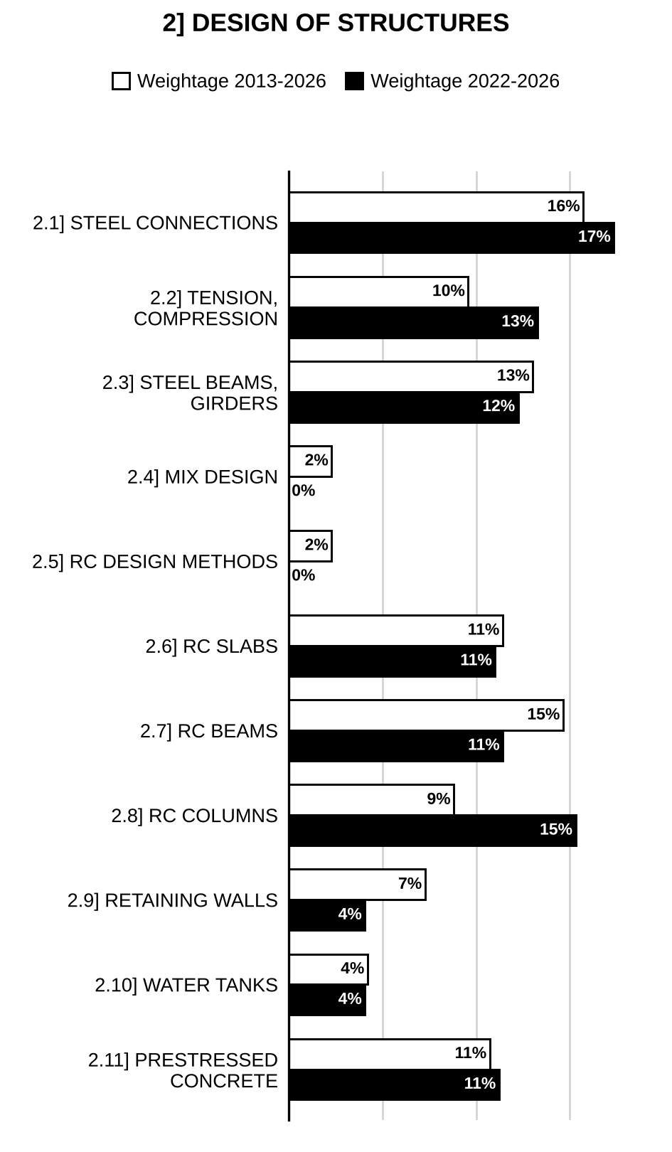
Here are all 125 Design of Structures: Steel, Concrete and Masonry Structures questions asked in UPSC Civil Engineering Optional Paper I from 2004 to 2026, arranged under the 11 topics of the official syllabus. Within each topic the latest questions come first.
Each question ends with a code such as [2024/15m/3b] – the year, the marks, the word limit (where UPSC set one) and the question number in the paper.
2.1] Steel design: safety factors and connections
22 questions
A vertical member in a truss is subjected to the following member force (factored): (i) Compressive force = 30 kN (dead and live load) (ii) Tensile force = 150 kN (dead and wind load) The member is composed of two numbers ISA connected to both sides of the gusset plate of thickness 10 mm. Find the number of bolts required at the joint. Assume bolt diameter = 16 mm, grade of bolt = 4.6, , , cross-sectional area at the threaded part of the bolt = 0.78 times that of shank. Use limit state method of design. [2026/10m/3a]
A tie member of a truss consisting of an angle-iron section ISA of Fe 410 grade, is welded to an 8 mm gusset plate. Design the weld to transmit a load equal to the full strength of the member. Assume shop welding. Take weld size as 4 mm and , properties of ISA are: , , , or
[Figure: Angle ISA lapped on an 8 mm gusset plate, connected leg 65 mm deep, fillet welds along the two edges of the connected leg (side welds along the top edge and the bottom edge, the bottom weld longer); end view shows the angle against the gusset plate with the centroid at 18.1 mm from the heel (outstanding leg side); dashed line marks the centroidal axis.] [2025/10m/1d]
Determine the maximum permissible load (P) on the bolt A. Assume the Bolt value as 45.3 kN.
[Figure: Bracket connection: a 12 mm thick gusset plate bolted to the flange of an ISMB250 column (flange width 200 mm) with four bolts in two vertical rows, gauge 120 mm (60 mm each side of the column centre-line), and two horizontal rows 160 mm apart, each 40 mm from the top and bottom edges of the bolted part of the plate (40 mm + 160 mm + 40 mm). Bolt A is the upper bolt in the row farther from the column centre-line (nearer the load). Vertical load P acts on the top edge of the gusset plate at 300 mm from the column centre-line.] [2024/10m/1d]
Two angles ISA 100×100×12 mm transmit an ultimate tensile force of 540 kN, acting through the C.G. of angle sections as shown in the Figure. The angles are connected to the gusset plate on either side by welding. Design the lengths and of the weld if the size of the fillet weld is 6 mm, MPa, partial safety factor for the weld . Relevant portion of the IS 800 : 2007 is enclosed.
[Figure: Angle ISA 100 × 100 × 12 mm lapped on a 12 mm thick gusset plate and connected by two longitudinal fillet welds: length along the upper edge (the edge from which the centroidal axis is 29.2 mm) and length along the lower edge; the 540 kN pull acts along the centroidal axis, 29.2 mm from the upper edge.]
[Enclosure printed at the end of the paper (p. 14): “Relevant Portion of IS 800 : 2007” – clauses 10.5.4.3 to 10.5.9 (plug welds, long side welds, intermittent welds, weld types and quality, design stresses in welds – shop welds , , site welds with of 1.5, long joints reduction factor , fillet welds applied to the edge of a plate or section).] [2024/20m/2c]
A tie member consisting of an ISA (E 250 grade of steel) is connected to a 12 mm thick gusset plate using a 6 mm fillet weld at site. The welding is done on its three sides as shown in the figure. The angle between fusion faces is 75°. Find the lengths of weld and , if the connection is designed to transmit a load equal to the design strength of the member. For ISA , and mm. Take and for site welding, . for 60° – 90° angle between fusion faces. For E 250 grade steel: MPa, MPa.
[Figure: Two views of the connection. End view: ISA 75 × 50 × 8 angle against a 12 mm gusset plate, the 75 mm leg vertical against the plate and the 50 mm leg outstanding at the bottom; centroidal axis (dashed line) marked 25.2 mm above the bottom (outer) face of the outstanding leg; 6 mm weld. Plan view: the angle ISA 75 × 50 × 8 lapped on the 12 mm gusset plate and fillet-welded on three sides – weld along the upper edge, an end weld across the 75 mm width of the connected leg, and weld along the lower edge (the edge nearer the centroidal axis, 25.2 mm from it).] [2023/10m/1e]
A vertical member of a truss consisting of an angle section ISA of E250 grade is welded to a 10 mm thick gusset plate. The factored tensile and compressive forces in the member are 100 kN and 90 kN respectively. Design the weld connection (shop weld) having weld size of 4 mm; only two sides of the angle are welded. for ISA . [2022/10m/1e]
Find the maximum load , which the bracket as shown can transmit. The bolt strength of 20 mm dia and 8.8 grade is assumed to be 82 kN, considering shear and bearing under limit state method:
[Figure: Bracket plate bolted to the flange of a vertical column by 6 bolts in two vertical rows of three. The two bolt rows are each 50 mm from the column centre line (rows 100 mm apart); vertical pitch of bolts 50 mm + 50 mm. Vertical load acts at the outer end of the bracket at an eccentricity of 400 mm from the column centre line (centroid of the bolt group).] [2022/15m/4a]
A bracket plate of thickness 12 mm is connected perpendicular to the flange of a column (ISMB 400). Design a connection for the bracket using the fillet weld to carry a vertical load of 200 kN acting at 250 mm from the face of the column. The grade of steel is E 250. Assume shop welding. Take ultimate stress of weld material, . [2021/10m/1c]
Two steel plates, each 100 mm wide and 10 mm thick are connected together by a lap joint using a single row of three bolts, along width, of property class 4.6. The diameter of each bolt is 16 mm and the ultimate tensile strength of steel plates is . Calculate the efficiency of the joint if the plates are in tension. Use limit state procedure. Given: for bolts of property class 4.6. [2020/10m/1c]
Design a full penetration butt weld to connect a 16 mm thick bracket plate perpendicular to the flange of a column. A factored load of 230 kN is applied to the bracket at a distance of 350 mm from the flange of the column. Field welds and steel of grade Fe 250 were used. Also give a neat sketch of the connection. Use limit state procedure. [2020/15m/3b]
16 mm plates are joined together by single riveted lap joint in one of the following ways. Calculate which of the two ways will give a stronger joint: (i) 24 mm rivets at 60 mm pitch (ii) 30 mm rivets at 90 mm pitch Given: , , [2018/10m/1b]
Check the adequacy of the hanger connection shown in the figure below. The end plate welded connection shown in the figure need not be designed. The end distance of the bolt is 35 mm. Two bolts of 30 mm diameter are used to make the connection. The end plate is 230 mm × 150 mm in size. For 30 mm bolt, , and , .
[Figure: Hanger connection: a 16 mm thick vertical hanger plate carrying a downward load of 200 kN is welded with 8 mm fillet welds to the underside of a 25 mm thick end plate, 230 mm long; the end plate is connected by two bolts, one near each end (end distance 35 mm), to the flange of the supporting member above.] [2018/20m/3c]
What are the advantages of High Strength Friction Grip bolts? How the load is transferred in High Strength Friction Grip bolts? Explain with sketches. [2017/10m/1b]
A square hollow section is connected to the flange of ISMB 600 as shown in the above figure. The bracket is subjected to symmetrical vertical and horizontal load of each 50 kN. The size of SHS is 150×150×6 mm. Find the weld size required for the connection.
[Figure: Elevation: a square hollow section (SHS) bracket, 150 mm deep, projecting horizontally from the flange of an ISMB 600 column and fillet-welded all round to the flange face; a vertical downward load acts on the top of the SHS at 100 mm from the flange face, and a horizontal load acts perpendicular to the plane of the elevation (shown ⊗). View A-A: the 150 × 150 SHS outline with the all-round weld on the flange; the vertical load acts downward at the centre of the top face and the horizontal load acts at mid-height (75 + 75) on the side face; width 150.] [2017/15m/4c]
Design a welded lap joint to join two plates of size 300 × 10 mm and 280 × 10 mm in Fe 410 grade steel to mobilise the tensile strength of the plates using field weld. Yield strength of material = 250 MPa; ; Partial safety factor for field weld = 1.5.
[Figure: Lap joint. Elevation: two plates overlapping, pulled apart by axial force P at each end, with a fillet weld at each end of the overlap. Plan: 280 × 10 mm plate (280 mm wide) lapped over the 300 × 10 mm plate (300 mm wide); overlap length L; fillet welds (hatched) on all four sides of the overlap – along both longitudinal edges of the 280 mm plate over the length L and across both transverse ends] [2015/10m/5e]
A bracket connection shown in figure, consists of a joist cutting welded to the flange of a column by shop fillet welds 8 mm on flanges and 6 mm on the web. Determine the safe service load ‘W’, the bracket can support at a distance of 200 mm from the face of the column if the steel grade is Fe 410. Partial factor of safety on shop weld = 1.25; Yield strength of steel = 250 MPa.
[Figure: Side elevation: joist cutting welded to the face of the column flange, load W at 200 mm from the column face; 6 mm fillet welds on both sides of the web over a depth of 200 mm; 8 mm fillet welds along the flanges. End view: joist cutting 250 mm deep with flanges 150 mm wide, welded to a column flange 250 mm wide] [2015/20m/8c]
A joist cutting is used as bracket to support a factored load of 200 kN. It is welded to column flange as shown in the figure given below. Find the size of fillet weld. Grade of steel is Fe 410. Use partial safety factor for shop weld, . While calculating the moment of inertia, ignore the moment of inertia of the flange weld about its own axis. Use limit state method.
[Figure: Bracket made from a cut ISMB 400 (tapered joist cutting) welded to the flange of an ISHB 450 column. Factored load 200 kN acts vertically on the top flange of the bracket at 170 mm from the column flange face. Welds: 120 mm long weld along the top flange, 120 mm long weld along the bottom flange, and 320 mm long welds along the web (vertical). “View of weld from XX”: two horizontal flange welds each 120 mm long, 400 mm apart (top to bottom), and two vertical web welds each 320 mm long between them] [2012/15m/8b]
Figure shows the cross-section of a plate girder. The shear force at this section equals 800 kN. Using 20 mm diameter bolts design (i) Flange to web connection, (ii) Flange angle to cover plate connection.
[Figure: Plate girder cross-section: web plate 6 mm thick; at each flange two ISA 130 × 130 × 12 angles, one on each side of the web; top and bottom cover plates 360 × 20 (20 mm thick); distance between the inner faces of the cover plates 1800; distance between the top and bottom edges of the web 1790 (each marked “Edge of the web”, slightly inside the backs of the angles); bolts connecting angles to the cover plate at 80 and 80 from the web centre line (gauge 80 mm on each side); bolts through the vertical legs of the angles connecting them to the web] [2011/30m/7a]
A steel flat 100 mm × 10 mm carries a tensile force of 16000 kg (160 kN). It is to be welded to a gusset plate with a lap of 10 cm. Determine the minimum size of the fillet weld. Permissible stress in shear = (). [2010/10m/5c]
In a powerhouse to replace a circular penstock of 1.2 m diameter is made out of 12 mm thick plate, lapping it and securing it by traverse fillet welds of 10 mm size, provided on the inside and the outside as shown in the figure. What safe internal pressure can be allowed in the penstock? Assume the permissible stress in weld as 110 MPa.
[Figure: Cross-section of the circular penstock, radius 0.6 m (marked from the centre), shell plate 12 mm thick, internal pressure ? shown by radial arrows; the lapped plate joint is secured by fillet welds of 10 mm size on the inside and the outside (labelled “Fillet weld” and “Fillet weld 10 mm”)] [2009/12m/5b]
A circular steel pipe of 150 mm and 10 mm thick is welded to a rectangular plate of 12 mm thick by fillet weld around the pipe. A vertical load of 10 kN is acting on the pipe at a distance of 400 mm from the weld in the longitudinal direction and 300 mm from the centre of the pipe transversely. Design the weld. [2009/20m/6a]
A tension member is of pair of equal angles ISA 65 × 65 × 6 placed back to back on either side of gusset plate 10 mm thick. Calculate maximum pull resisted by the member. Design the welded connection with the Gusset plate. . [2004/12m/5a]
2.2] Steel tension and compression members
14 questions
A tension member consists of two angle-irons, back to back, of size ISA and is connected to the same side of a gusset plate by a single row of six 20 mm diameter bolts as shown in the figure. Calculate the load carrying capacity when the two angles are tack-bolted. Yield stress of steel () = 250 MPa and Ultimate tensile stress () = 410 MPa.
[Figure: (a) Cross-section: vertical gusset plate with two ISA angles placed back to back, both connected legs bearing on the same face of the gusset plate (one angle above, one below), the outstanding legs (75 mm, thickness 8 mm) projecting horizontally and joined by tacking bolts; in each connected leg the bolt line is 40 mm from the back of the outstanding leg and 35 mm from the edge of the leg; bolt hole dimension 22 mm. (b) Elevation: gusset plate with the two angles, each connected by one row of six bolts; edge distance 35 mm, pitch 50, 50, 50, 50, 50 mm, end distance 35 mm; = 250 mm; failure sections marked 1–1, 2–2 and 3–3.]
Given: where, = outstand leg width = shear lag width = length of the end connection for one or two bolts for three bolts for four or more bolts [2025/20m/3c]
What are the different modes of failure of a structural steel tension member? Explain with sketches. [2024/10m/4c]
A built-up column of effective length 10 m is designed by placing two ISMC 300 @ 363 N/m back to back at a spacing ‘S’ mm. The column is to carry a factored axial load of 1100 kN. Find the economical spacing ‘S’ of the two channel sections. Also design the batten system for the column. M 20 bolts of grade 4.6 are used for making the connections. Do not design the connections. Use E 250 grade of steel. For connections: Edge distance = 32 mm, Gauge distance = 50 mm. Properties of ISMC 300: , mm, mm, ,
[Figure: ISMC 300 channel section: depth 300, flange width 90, flange thickness , web thickness , (distance of centroidal axis y–y from the back of the web); axes z–z and y–y. (All dimensions are in mm)] [2023/20m/3b]
A laced column of height 8 m is made of 2 nos. ISMC 350 placed back-to-back. The column is restrained against translation and free against rotation at both ends in both directions. Find the distance between them to carry maximum axial compressive load and calculate the factored load-carrying capacity of the column using limit state method. The properties of ISMC 350 are , , , . Given:
| 20 | 30 | 40 | 50 | 60 | 70 | 80 | 90 | 100 | |
| (MPa) | 224 | 221 | 198 | 183 | 168 | 152 | 136 | 121 | 107 |
| 110 | 120 | 130 | 140 | 150 | 160 | 170 | 180 | ||
| (MPa) | 95 | 84 | 74 | 66 | 59 | 53 | 48 | 44 |
[2022/15m/3b]
A single angle strut ISA 80 × 80 × 10 is used to carry a service load of 80 kN. The centre to centre distance between the end connections is 2 m. The end connection is done by two bolts. Check the adequacy of the section to carry this load. The grade of steel is E 250. Use limit state method. Take , and for ‘fixed’ fixity as per code IS 800 : 2007. Properties of ISA 80 × 80 × 10: , , , , [2021/15m/3b]
Determine the effective net area for the angle section shown in the figure, subjected to tensile force. Bolts are of grade 4.6, and the steel is of grade Fe 410.
[Figure: ISA 125 × 95 × 10 mm angle connected to a 12 mm thick steel plate by its 125 mm leg (vertical); the 95 mm leg outstanding (horizontal). Connected leg: 18 mm bolts staggered at 50 mm pitch on two gauge lines, the first 35 mm from the toe of the leg and the second a further 50 mm away. Outstanding leg: 20 mm bolts at 100 mm pitch, on a gauge line 55 mm from the back of the angle (face of the plate) and 40 mm from the toe. All dimensions in mm.] [2020/10m/5b]
A built-up steel column section is as shown in the figure. Determine the axial load capacity in compression for the data given below: MPa, m, mm, The connection between web and flanges are welded connection. Both the column ends are restrained in direction and position. The buckling curve to be used along zz-axis is ‘b’ and that along yy-axis is ‘c’.
[Figure: Built-up welded I-section: two flange plates 300 mm wide × 30 mm thick, web plate 30 mm thick; clear depth of web between the flanges 400 mm; fillet welds at the web–flange junctions. Axis z–z horizontal through the centroid; axis y–y vertical along the web.]
The design compressive stresses for slenderness ratio for curve ‘b’ and ‘c’ are given below.
| Slenderness Ratio | 40 | 50 | 60 | 70 | 80 | 90 |
| Design compressive stress, in for curve ‘b’ | 206 | 194 | 181 | 166 | 150 | 134 |
| Design compressive stress, in for curve ‘c’ | 198 | 183 | 168 | 152 | 136 | 121 |
[2019/15m/3b]
Determine the maximum load that a discontinuous strut having a single angle of length 1.75 m in a roof truss can carry, if it is connected at the ends by a single bolt. Take of steel as 250 MPa. For the given angle, the cross-section area and radius of gyration are and 10.7 mm, respectively. Take . [2014/10m/1b]
A built-up column consists of three ISWB 450 @ 0.794 kN per m connected effectively to act as one column. (See above figure.) Determine the safe load carrying capacity of built-up section if the unsupported length of column is 4.25 m. Properties of ISWB 450 @ 0.794 kg per m. Area = 101.15 sq cm = thickness of web = 9.2 m; M.Pa = yield stress.
[Figure: Built-up column section of three ISWB 450: two ISWB sections placed upright (webs vertical, flanges horizontal) at the left and right, and a third ISWB placed between them with its web horizontal along the x–x axis and its flanges vertical, the flanges of the middle section bearing against the webs of the outer sections. Axis x–x is horizontal through the centroid; y–y axes are marked through the webs of the two outer sections. No dimensions are given.]
| Slenderness ratio | 10 | 20 | 30 | 40 | 50 | 60 | 70 |
| Permissible stress in axial compression in M.Pa M.Pa | 150 | 148 | 145 | 139 | 132 | 122 | 112 |
[2013/10m/5a]
A tension member 0.9 m long has to resist a service dead load of 20 kN and service live load of 60 kN. Design a rectangular flat bar of standard structural steel of grade Fe 410. Assume that the member is connected by one line of 16 mm diameter bolts of grade 4.6. Use limit state method. Given: Partial safety factor for material, and . Partial safety factor for dead load and live load, . [2012/15m/8a]
Design the battens for top chord member of a steel bridge truss. It is 6 m long and subjected to an axial load of 600 kN. Slenderness ratio is limited to 70 – 90. Allowable compressive stress = . The member consists of 2 ISMC 175 with a steel plate of 240 × 8 mm at top.
[Figure: Built-up section: two ISMC 175 channels placed back to back with their webs vertical and flanges pointing outwards, 90 mm apart (dimension between the webs), with a 240 × 8 plate across the top flanges; axes x–x (horizontal) and y–y (vertical, midway between the channels); a batten (dashed) across the bottom flanges]
Properties of ISMC: , , kg/m, , mm, cm, mm, cm, cm
| Allowable Stress in Axial Compression () | |
| 70 | 107.5 |
| 80 | 100.7 |
| 90 | 92.8 |
| 100 | 84.0 |
| 110 | 75.3 |
| 120 | 67.1 |
| 130 | 59.7 |
| 140 | 53.1 |
[2011/12m/5b]
Design a suitable single lacing for the column whose cross-section is shown in the figure. The slenderness ratio for the column is 24. Use 65 mm × 15 mm plate for lacing. Axial load on the column is 1750 kN. For the column section For lacing plate.
| (MPa) | |
| 100 | 84 |
| 110 | 75.3 |
| 120 | 67.1 |
| 130 | 59.7 |
[Figure: Built-up column of two ISWB 350 @ 599 N/m sections placed side by side (webs parallel), connected by single lacing on the flanges (labelled “Lacing”). Each flange is 200 mm wide, with 100 mm from the outer flange edge to the web centre line; the centre lines of the two webs are 300 mm apart; the lacing is connected to the flanges on a line marked 50 mm from the flange edge] [2009/20m/7a]
A tension member is of pair of equal angles ISA 65 × 65 × 6 placed back to back on either side of gusset plate 10 mm thick. Calculate maximum pull resisted by the member. Design the welded connection with the Gusset plate. . [2004/12m/5a]
A built-up laced column of overall square cross-section, 300 mm side has been formed by placing four angles of ISA 50 × 50 × 6 at the corners of the square. If the effective height of column is 10 m, calculate the load carrying capacity of the column. Also design lacings.
| 40 | 50 | 60 | 70 | 80 | 90 | 100 | 145 | |
| (MPa) | 164 | 153 | 139 | 125 | 111 | 98 | 86 | 50 |
For ISA 50 × 50 × 6, Area = , , . [2004/20m/6c]
2.3] Steel beams and girders
11 questions
A steel plate girder is subjected to a maximum factored shear force of 2800 kN. The cross-section of the girder is shown in the figure. Design a suitable fillet weld to connect flange plates to the web. Assume shop welding. E250 grade of steel having MPa is used. Use limit state method of design. Take :
[Figure: Welded plate girder (I-section): top and bottom flange plates 650 mm × 25 mm; web 15 mm thick, 1500 mm deep between the flanges; fillet welds on both sides of the web at each web–flange junction.] [2026/10m/1e]
A simply supported beam ISMB 400 @ 61.6 kg/m has an effective span of 5 m. Find the design bending strength of the beam and the intensity of u.d.l. that the beam can carry under service condition. Assume that the beam is laterally supported. The grade of the steel is E250. The class of section is plastic. For ISMB 400, , , . Assume . Use limit state method of design. [2026/10m/4b(i)]
For an industrial building, a gantry girder (without lateral restraint along its span) is designed to carry an overhead travelling crane for the following data: Centre-to-centre distance between columns (i.e., span of the gantry girder) = 7.5 m Crane capacity = 200 kN Self-weight of the crane girder excluding trolley = 200 kN Self-weight of trolley, electric motor, hook, etc. = 40 kN Minimum hook approach = 1.2 m Distance between wheel centres = 3.5 m Centre-to-centre distance between gantry rails (i.e., span of the crane) = 15 m Self-weight of the rail section = 300 N/m Yield stress of steel = 250 MPa Data analysis provided the following information: Total vertical design bending moment (including the bending moment due to drag), kN-m Horizontal design bending moment (due to surge load), kN-m Based on the analysis and other governing criteria, for the design of gantry girder, it was decided to use ISMB 600 @ 1230 N/m with a channel ISMC 300 @ 363 N/m at the top as shown in the figure:
[Figure: Gantry girder section (all dimensions in mm): ISMB 600 (overall depth 600, flange width 210, flange thickness 20.8, web thickness 12) with an ISMC 300 channel (web 300 wide, thickness 7.8, flanges 90 deep turned downwards) placed over its top flange; axes z–z (horizontal) and y–y (vertical) shown. (All dimensions are given in mm)]
The properties of the sections are as follows:
| ISMB 600 @ 1230 N/m | ISMC 300 @ 363 N/m |
| mm | mm |
| mm | mm |
| Width of flange, mm | mm |
| Radius at root, mm | Centre of gravity, mm |
Check the adequacy of the chosen section for the moment capacity. Assume any other data suitably. [2026/20m/4c]
During the design of a beam, an ISMB 550 @ 1.037 kN/m is selected for use as a simply supported beam of 7 m span carrying a reinforced concrete floor capable of providing lateral restraint to the top compression flange. The total uniformly distributed load is made up of 100 kN dead load and 150 kN imposed load. In addition to this load, the beam also carries a point load at its midspan which is made up of 50 kN dead load and 50 kN imposed load. Check the adequacy of the section for the following: (i) Shear strength (ii) Bending strength (iii) Deflection (iv) Web buckling at support Assume the section is plastic. Given: Stiff bearing length = 100 mm, MPa, MPa, , For plastic section , For simply supported beam,
| KL/r | 90 | 100 | 110 | 120 |
| (MPa) | 121 | 107 | 94.6 | 83.7 |
Properties of ISMB 550: Elastic section modulus, ; Plastic section modulus, ; Moment of Inertia about major axis,
[Figure: ISMB 550 cross-section: overall depth 550, flange width 190, flange thickness , web thickness , root radius , toe radius ; major axis z–z, minor axis y–y. (All dimensions are in mm)] [2023/20m/2b]
A simply supported steel beam of span 4 m carries a factored point load of 450 kN at its mid span. The beam is laterally supported. Check the adequacy of ISMB 400 section to carry this load. If it becomes unsafe, re-design it by providing extra cover plate to make it safe. Assume the section is plastic. Grade of steel is E 250. Use limit state method. Section properties of ISMB 400: , , , , , [2021/20m/7c]
A welded plate girder 22 m in span is laterally restrained throughout, and carries a uniformly distributed load of 100 kN/m excluding the self weight. The girder is without intermediate transverse stiffeners. The steel used is of grade Fe 410. Design the cross-section and the welded connections. Draw a neat sketch of the designed section. Use limit state design method. The plate girder is fabricated in the workshop. [2020/25m/7c]
Design a bearing plate at the support for ISMB 600 @ 1202.71 N/m resting on a brick masonry wall 230 mm thick for the support reaction of 180 kN. Assume the permissible bearing stress for brick wall be and partial safety factor . The sectional properties of ISMB 600 are as follows: Grade of steel = 250 MPa; Width of flange = 210 mm; Thickness of flange = 20.8 mm; Thickness of web = 12 mm; Radius of root R = 20 mm. [2019/10m/1c]
A steel beam section ISMB 400 @ 604.30 N/m is supported on RCC column and has bearing length 150 mm. Calculate the load bearing capacity of this steel beam under web buckling at support. Assume the grade of steel Fe 410 and permissible stresses () according to buckling curve ‘C’ are as given below. The cross-sectional properties of ISMB 400 are as Sectional Area A = ; Width of Flange = 140 mm; Thickness of Flange = 16 mm; Thickness of Web = 8.9 mm; = 14.0 mm Permissible (Design Compressive) stress () as per buckling curve ‘C’
| 70 | 80 | 90 | 100 | 110 | |
| () | 152 | 136 | 121 | 107 | 94.6 |
[2019/15m/6b]
Design a simply supported beam with an effective span of 8 m carrying a factored u.d.l. of 10 kN/m. The compression flange is restrained laterally along its entire length and the yield stress of steel is 250 MPa. The properties of ISMB 300 section are given below: Area = 5870 ; mm; mm; mm; mm; ; mm; mm; Unit weight kN/m; [2016/20m/7b]
A simply supported beam (ISMB 350) is to carry an imposed load of 20 kN/m. The beam ends are resting on 250 mm thick walls with bearing plates (smooth) with clear span of 6.25 m. The beam is laterally restrained and is made of MILD STEEL. The beam supports a floor slab. Check the beam section against bending, shear and deflection. The section properties of ISMB 350 are: ; Weight = 524 N per m = Thickness of web = 8.1 mm; Area = 6671 sq mm = Depth of the beam = 350 mm Assume allowable bending stress, allowable shear stress as per code. [2013/20m/6a]
Figure shows the cross-section of a plate girder. The shear force at this section equals 800 kN. Using 20 mm diameter bolts design (i) Flange to web connection, (ii) Flange angle to cover plate connection.
[Figure: Plate girder cross-section: web plate 6 mm thick; at each flange two ISA 130 × 130 × 12 angles, one on each side of the web; top and bottom cover plates 360 × 20 (20 mm thick); distance between the inner faces of the cover plates 1800; distance between the top and bottom edges of the web 1790 (each marked “Edge of the web”, slightly inside the backs of the angles); bolts connecting angles to the cover plate at 80 and 80 from the web centre line (gauge 80 mm on each side); bolts through the vertical legs of the angles connecting them to the web] [2011/30m/7a]
2.4] Concrete mix design
5 questions
The design mix proportion of Cement : Fine agg. : Coarse agg. : Water for a concrete mix of grade M-25 at Saturated Surface Dry (SSD) condition is 1 : 1.2 : 2.4 : 0.4 (by weight). Find out the revised mix proportion due to change of material characteristics (Fine and Coarse agg.) for raining day before casting at site. Given: (i) Sp. gravity of Fine and Coarse agg. = 2.6 and 2.65 respectively. (ii) Surface moisture (%) on Fine and Coarse agg. = 2.5 and 1.5 respectively. How the durability factor is taken up during concrete mix design as per I.S. code? [2017/10m/5b]
State the Abram’s law on water-cement ratio. [2015/5m/6c(i)]
Name the various grades of ordinary Portland cement. [2015/5m/6c(ii)]
Calculate the quantities of ingredients required to produce one cubic meter of structural concrete. The mix proportions are 1 : 1.33 : 2.80 by dry volume of cement, with a water-cement ratio of 0.48 (by mass). The bulk densities of cement, sand and coarse aggregates are , and , respectively, and the corresponding specific gravities are 3.15, 2.60 and 2.62, respectively. The percentage of entrained air is 2.0. [2014/10m/3a(ii)]
In a laboratory test for a mix design, the coarse aggregates and fine aggregates are sieved and weight retained on each sieve are given in the table. Find the fineness modulus for each:
| Sl. No. | IS Sieve | Weight retained in kg for coarse aggregates | Weight retained in gm for fine aggregates |
| 1 | 40 | 2.1 | – |
| 2 | 20 | 2.9 | – |
| 3 | 10 | 1.45 | – |
| 4 | 4.75 | 2.55 | 20 |
| 5 | 2.36 | 1.00 | 100 |
| 6 | 1.18 | – | 100 |
| 7 | 600 μ | – | 190 |
| 8 | 300 μ | – | 350 |
| 9 | 150 μ | – | 240 |
| Total | 10 | 1000 |
[2009/12m/5a]
2.5] RC design philosophy and IS codes
3 questions
Draw characteristic stress-strain curve for concrete, mild steel and HYSD steel in flexure giving all relevant values as per codal recommendations for limit state design of RCC structures. [2020/10m/1b]
Explain the principles of working stress method and limit state method of design of R.C. members. [2018/15m/7b]
Define characteristic strength of reinforcing steel. [2015/5m/6c(iii)]

Preparing for Prelims too?
Our UPSC Prelims Topic-wise PYQ eBook covers every Prelims question with detailed explanations, so you can see exactly where UPSC asks from.
View the BookDownload Free Sample2.6] RC slabs
14 questions
A reinforced concrete passenger shelter is to be constructed as shown in the figure. The thickness of the slab is 150 mm. The ceiling plaster and roof finish load is . The roof is inaccessible. Design and detail the slab only. Use M20 grade concrete and Fe500 grade steel. Use limit state method. Given:
| 0.3 | 0.4 | 0.5 | 0.6 | 0.7 | 0.8 | 0.9 | 1.0 | |
| (%) | 0.07 | 0.094 | 0.119 | 0.143 | 0.168 | 0.193 | 0.219 | 0.245 |
Modification Factor vs. Percentage Tension Reinforcement graph is given below:
[Figure: TOP PLAN: rectangular roof slab 1500 mm + 250 mm + 1500 mm wide and 1000 mm + 2000 mm + 1000 mm long; a central beam 250 mm wide (dashed lines) runs along the full length; two columns under the beam, 2000 mm apart, each 1000 mm from the ends of the slab; section A–A marked across. VIEW AA: 150 mm thickness slab cantilevering 1500 mm on each side of the beam, the beam resting on a single column fixed at the ground.]
[Figure: Graph “MODIFICATION FACTOR FOR TENSION REINFORCEMENT”: MODIFICATION FACTOR (vertical axis, 0 to 2.0, labelled 0.4, 0.8, 1.2, 1.6, 2.0) against PERCENTAGE TENSION REINFORCEMENT (horizontal axis, 0 to 3.0, labelled 0.4, 0.8, 1.2, 1.6, 2.0, 2.4, 2.8, 3.0); five decreasing curves for = 120, 145, 190, 240 and 290. Note: is steel stress of service loads in . ] [2026/20m/3c]
Design a (tread and riser) dog-legged staircase of an office building, given the following data: Height between floors = 3.2 m Riser = 160 mm Tread = 270 mm Width of flight = Landing width = 1.25 m Live load = Finishes load = Consider the landing to be supported only on two edges perpendicular to the risers. Take density of concrete = . where .
[Figure: Plan of the dog-legged staircase: overall width 2600 mm made up of two flights 1250 mm wide separated by a 100 mm gap; flights (treads drawn as parallel lines) 2430 mm long between landings; landing at each end 1250 mm long shown as 625 + 625 mm, with a dashed line at 625 mm in each landing; walls (hatched) along the outer long edges at the landings.] [2025/14m/4c(ii)]
Design a floor slab to cover a room with internal dimensions of 4.5 m × 6.0 m. The slab is simply supported on all the sides on 230 mm thick masonry walls. The slab carries a live load of 4.0 kN/m² and a dead load due to finishing work of 1.0 kN/m². The corners of the slab are prevented from lifting up. Use M 20 concrete and Fe 415 steel. Assume mild exposure conditions.
Table: Bending Moment coefficients when four edges are discontinuous
| Short span coefficient, | Long span coefficient, | ||||||
| 1.0 | 1.1 | 1.2 | 1.3 | 1.4 | 1.5 | for all values of | |
| 0.056 | 0.064 | 0.072 | 0.079 | 0.085 | 0.089 | 0.056 |
[Figure: Graph “Modification Factor for Tension Reinforcement”: modification factor (vertical axis, 0 to 2.0, grid at 0.4, 0.8, 1.2, 1.6, 2.0) against percentage tension reinforcement (horizontal axis, 0 to 3.0, labelled 0.4, 0.8, 1.2, 1.6, 2.0, 2.4, 2.8, 3.0); five falling curves for , 145, 190, 240 and 290 (upper to lower). Note: is steel stress of service loads in . Below the graph: ] [2023/20m/3a]
The floor slab of a room has clear dimensions of 4.0 m × 9.0 m and the slab is simply supported on 230 mm thick masonry walls. The floor loading consists of a live load of and dead load due to finishing work is . Steel of grade Fe 415 and concrete of grade M 25 is used for construction. Design the floor slab and check it for deflection. Use limit state design method.
[Figure: Chart “Modification Factor for Tension Reinforcement”: Modification Factor (0 to 2.0) on the vertical axis against Percentage Tension Reinforcement (0 to 3.0, marked 0.4, 0.8, 1.2, 1.6, 2.0, 2.4, 2.8, 3.0) on the horizontal axis; five decreasing curves for = 120, 145, 190, 240 and 290 (the curve for = 120 highest, flattening near 1.0 at 3.0%; = 290 lowest, flattening near 0.7). Note: is Steel Stress of Service Loads in . ] [2020/20m/6c]
Design a floor slab for an interior roof slab with clear dimensions of 8.5 m × 3.5 m for a building located in Delhi. The slab is resting on 230 mm thick masonry walls. The superimposed load may be taken as . Use M 25 grade of concrete and Fe 415 grade of steel.
The following data may be used:
| Exposure | Moderate | Severe | Very Severe |
| Nominal concrete cover (in mm), not less than | 30 | 45 | 50 |
| Basic values of span to effective depth ratios for spans up to 10 m | Cantilever | Simply Supported | Continuous |
| 7 | 20 | 26 |
[Figure: Chart “Modification Factor for Tension Reinforcement”: Modification Factor (0 to 2.0) on the vertical axis against Percentage Tension Reinforcement (0 to 3.0, marked 0.4, 0.8, 1.2, 1.6, 2.0, 2.4, 2.8, 3.0) on the horizontal axis; five decreasing curves for = 120, 145, 190, 240 and 290 (the curve for = 120 highest, flattening near 1.0 at 3.0%; = 290 lowest, flattening near 0.75). Note: is steel stress of service loads in . ] [2019/15m/7b]
A straight stair in a residential building is supported on a wall at one side and by a stinger beam on the other side, with a horizontal span of 1.2 m. The risers are 150 mm and treads 300 mm. Design the steps. Use M 20 concrete and Fe 415 steel. Take live load as . [2018/20m/6a]
Details of a dog-legged stair for a building is shown in the above figure. The floor to floor height is 3.0 m. The live load may be taken as thickness of the stair slab is 150 mm. The rise and tread are 150 mm and 250 mm respectively. Design and detail the typical flight. Use M-25 of concrete and Fe-500 grade of steel. Use limit state method.
[Figure: Plan of a dog-legged staircase in a rectangular stair hall framed by beams 250×400 on all four sides (left, top, right and bottom beams marked 250×400), with 250×250 columns (Typ) at the four corners. Plan dimensions along the length (mm): 1200 (floor landing at left) – 2250 (going of the flights) – 1200 (half landing at right, marked “half landing”). The lower flight (treads drawn) rises from left to right (arrow marked “up”); the upper flight returns from right to left (arrow) above it; the two flights are separated by a line along the middle (the label 250×400 inside the plan, just above the bottom beam, marks that beam). A table of design values is given below the plan.]
| 2.5 | 2.6 | 2.7 | 2.8 | 2.9 | 3.0 | 3.1 | |
| pt | 0.65 | 0.695 | 0.727 | 0.76 | 0.794 | 0.826 | 0.863 |
[2017/20m/2c]
A slab is reinforced with 10 mm diameter bars at 200 mm c/c located at an effective depth of 125 mm. M 20 concrete and Fe 415 steel are used. Find the Moment of resistance of the slab using either working stress method or limit state of strength (ultimate limit state of stress) method as per I.S. code. (I.S. codes are not applied during examination). What shall be the overall depth of slab? Modular ratio is 13.33. [2013/20m/7a]
The following figure shows the flight of staircase of a hospital building which is simply supported on two walls at two ends. Assume suitable live load, finish load and other dead loads: For the given data– (i) find at which section, the maximum moment will occur; (ii) find the total steel and give total number of bars of particular dia to be provided in the flight; (iii) find the nominal shear stress at critical section; (iv) show the detailing of reinforcement at without any curtailment of main longitudinal bars. No need to apply deflection check. Use limit state method.
[Figure: Staircase flight (elevation): upper landing 1.2 m long resting at its left end on a 230 mm wall; going of 8 @ 250 mm (tread) with rise = 150 mm, the waist slab sloping down to the right; lower landing 1 m long resting at its right end on a 230 mm wall; total vertical rise between the landings 1.2 m; width of flight = 1.5 m; the junction of the upper landing and the sloping waist slab is circled and marked “Detail A”] [2012/15m/6a]
The following figure shows the plan of slab of a framed building. It consists of several panels with different edge conditions: Assume: DL on slabs = ; IL on slabs = . The positive and negative short-span and long-span factored moments are given in the table for three panels: From the given moments, work out positive and negative bending moment coefficients, and indicate for which edge condition and for which long-span to short-span ratio, they are applicable.
[Figure: Plan of a slab with columns at the grid intersections; bays 5.5 m and 4 m in one direction and 5 m and 5 m in the other; the left and top edges are the outer (discontinuous) edges of the floor, the right and bottom edges are shown with break lines (slab continues). Top-left panel (5.5 m × 5 m) is ; in the next row, the 5.5 m × 5 m panel is (below , along the left edge) and the 4 m × 5 m panel is (interior)]
| Slab | Short-span (+)ve moment (kN-m per m width) | Short-span (–)ve moment (kN-m per m width) | Long-span (+)ve moment (kN-m per m width) | Long-span (–)ve moment (kN-m per m width) |
| 13.5 | 17.9 | 11.8 | 15.86 | |
| 10.8 | 14.5 | 9.46 | 12.5 | |
| 7.34 | 9.72 | 5.18 | 6.91 |
[2012/15m/6b]
Design a two way slab of size 3.5 m × 4.5 m to support an imposed load of and floor finish of . Two adjacent edges of slab are discontinuous. Assume moderate exposure condition. Use M 20 grade of concrete and Fe 415 HYSD bars. Assume depth as per L/d ratio. Adopt 10 mm dia bars. Safe shear stress is given as . Draw one typical cross-section along longitudinal direction of slab and show details of steel. Use following data for calculating moment:
| Short span coefficient – Negative moment at continuous edge | Short span coefficient – Positive moment at mid-span | Long span coefficient | |
| 1.2 | 0.060 | 0.045 | 0.047 |
| 1.3 | 0.065 | 0.049 | 0.047 |
[2011/30m/8a]
A reinforced concrete slab 3.0 m × 3.0 m is simply supported on two parallel walls 30 cm wide with a clear distance of 2.4 m between them. It carries a uniformly distributed load of including finishes and impact load. Design the slab using M-20 concrete and Fe-415 grade HYSD bars by working stress design method. Sketch the reinforcement. Note that available reinforcement bars are of 16 mm dia. [2010/30m/7a]
A lounge in an office building is circular in plan, supported on four columns and connected by circumferential beams at top connecting the columns. The diameter of circumferential beam is 6 m. Design a suitable slab for the above system, taking as the superimposed load. Adopt M 20 grade concrete and Fe 415 grade steel. [2009/20m/6b]
Design a reinforced concrete floor slab for a residential building for the following particulars, adopting limit state method of design. Clear dimensions of room: 3 m × 8 m Wall thickness: 230 mm Live load on floor: 2 kN/sq. m Finishes: 1 kN/sq. m Concrete: M 20 Steel: Fe 415 Minimum total depth of slab: 125 mm. [2004/20m/7c]
2.7] RC beams
18 questions
A simply supported reinforced concrete beam of size mm (effective) is reinforced with 4 bars of 16 mm ϕ of Fe 500 grade steel. Determine the anchorage length of the bars at simply supported end if it is subjected to a factored shear force of 350 kN at the centre of 300 mm wide masonry support. The concrete mix of grade M25 is to be used. Bond stress () for plain bar for M25 = 1.4 MPa [2025/10m/3b]
For a continuous beam ABCDEFG, show the pattern of loading for the live load for the following: (A) max –ve bending moment at support C (B) max +ve bending moment in span CD (C) max –ve bending moment in span CD (D) max +ve bending moment at support C. [2025/6m/4c(i)]
From first principles, derive the expression for determining the depth of neutral axis, for a rectangular reinforced concrete section without compression reinforcement, as per Limit State Method. Use the stress-strain curves for concrete and reinforcing bars shown in the Figs. 1 and 2.
[Figure: Fig. 1 STRESS-STRAIN CURVE FOR CONCRETE: stress against strain; parabolic curve rising from the origin to a maximum at strain 0.002, then constant up to strain 0.0035; three such curves with plateaus at , and .]
[Figure: Fig. 2 REPRESENTATIVE STRESS-STRAIN CURVES FOR REINFORCEMENT. 23A Cold Worked Deformed Bar: curves for and , linear with up to , then non-linear with stress levels , , , , and corresponding to inelastic strains 0.0001, 0.0003, 0.0007, 0.001, 0.002, 0.003, 0.004 (dashed offset lines). 23B Steel Bar with Definite Yield Point: linear-elastic with up to (and ), then horizontal.] [2024/10m/2b]
Design only the flexural reinforcement for a T-beam section to resist a service moment of 200 kNm. The details of the section are given below: Breadth of flange mm; Breadth of web mm; Effective depth of the T-beam d = 455 mm; Overall depth of the T-beam D = 500 mm; Depth of flange mm. Use M25 grade concrete and Fe 500 grade steel. Relevant portion of the IS 456 : 2000 is enclosed.
[Enclosure printed at the end of the paper (p. 15): IS 456 : 2000 ANNEX G (Clause 38.1) “MOMENTS OF RESISTANCE FOR RECTANGULAR AND T-SECTIONS” – G-1 Rectangular sections (G-1.1 without compression reinforcement: , , ; G-1.2 with compression reinforcement) and G-2 Flanged sections (G-2.2: when does not exceed 0.2; G-2.2.1 with when exceeds 0.2; G-2.3).] [2024/20m/3b]
A reinforced concrete beam of 250 mm × 500 mm is reinforced with 3 nos. 16 mm dia bars as tension reinforcement. The nominal cover to the reinforcement is 30 mm and diameter of stirrups is 8 mm. Calculate the moment of resistance of the beam. Use M20 and Fe500. Adopt limit state method of design. [2022/10m/1b]
Determine the moment of resistance of the T-beam as shown in the figure. Use limit state method. Take M 20 grade of concrete and Fe 415 HYSD bars.
[Figure: T-beam section: flange width 1000 mm, flange thickness 100 mm; web width 300 mm; depth of web below the flange 400 mm (overall depth 500 mm). Tension steel 4 nos 25 φ bar in one layer with centres 50 mm above the bottom of the web.] [2021/10m/5b]
Size of a rectangular simply supported beam is restricted to 300 mm × 500 mm (overall). The effective span of the beam is 5 m. The beam is subjected to an imposed load of 64 kN/m. Design the beam using M 20 grade of concrete and Fe 415 grade of steel. Take effective cover as 40 mm and width of supporting wall as 250 mm. The stress in the reinforcement can be derived from the stress-strain curve given below. Use limit state method of design.
[Figure: Stress-Strain Curve for Cold Worked Deformed Bar. Stress (vertical) against Strain (horizontal). Two curves: an upper curve levelling off at and a lower (design) curve levelling off at ; initial straight portion with . Stress levels marked on the vertical axis: 0.80 , 0.85 , 0.90 , 0.95 , 0.975 and , with dashed lines parallel to the elastic line showing the corresponding inelastic strains 0.0001, 0.0003, 0.0007, 0.001, 0.002 and 0.003 marked on the strain axis (strain axis also marked 0.004).] [2021/20m/6c]
A reinforced concrete beam having a clear simply supported span of 6 m is required to support live and superimposed loads of 18 kN/m and 12 kN/m respectively. The materials to be used are M 25 grade concrete and Fe 250 grade steel. Design the section of the beam, and the main longitudinal reinforcement. The width of support is 500 mm. Use limit state design method. [2020/15m/2b]
A reinforced concrete beam of rectangular section 300 mm × 500 mm is reinforced in tensile zone by 4 bars of 16 mm diameter having an effective cover of 40 mm. The beam is loaded with a factored load including its self-weight as shown in the figure below. Design the vertical shear reinforcement for the beam at critical section for shear. Take M 25 grade of concrete and Fe 415 grade of steel.
[Figure: Beam with a hinged support at the left end and a second (hinged) support 10 m from it, with an overhang of 4 m beyond the second support (total length 14 m); uniformly distributed load 30 kN/m over the whole length (span 10 m and overhang 4 m).]
Use the following data: For M 25 concrete,
| 0.25 | 0.5 | 0.75 | 1.00 | |
| () | 0.36 | 0.49 | 0.57 | 0.70 |
[2019/10m/1b]
Calculate the ultimate flexural strength of a T-beam section having the following sectional properties: Width of the flange = 1200 mm Depth of the flange = 120 mm Width of the rib = 300 mm Effective depth = 600 mm Area of tensile steel = 8 bars of 25 mm diameter Materials: M 20 grade concrete and Fe 415 HYSD bars. [2018/10m/1c]
A reinforced concrete cantilever beam (300 mm × 600 mm) of span 2 m carries a u.d.l. of 125 kN/m including its self weight. The beam is reinforced with 4 Nos. 25 mm dia bars at top and 2 Nos. 20 mm dia bars at bottom. Design the shear reinforcement and draw the cross-section of the beam. Use M-25 and Fe-500. Use limit state method of design. Given:
| 0.25 | 0.5 | 0.75 | 1.0 | 1.25 | 1.50 | 1.75 | |
| (MPa) | 0.36 | 0.49 | 0.57 | 0.64 | 0.70 | 0.74 | 0.78 |
[2017/15m/6b]
A reinforced concrete rectangular section of size 300 mm × 600 mm (effective) is reinforced with 4 bars of 20 mm dia on the tension side. Determine the safe uniformly distributed load that the beam can carry over a simply supported effective span of 8 m. The grade of concrete and steel used are M 20 and Fe 415 respectively. For the given environmental exposure, the effective cover to reinforcement is 50 mm. [2016/10m/1b]
A reinforced concrete beam of rectangular section has a width of 230 mm and an effective depth of 500 mm. The effective covers to tension and compression reinforcements are 40 mm and 30 mm respectively. The beam is reinforced with 3 bars of 20 mm dia in tension and 3 bars of 16 mm dia in compression. Find the limiting moment carrying capacity of the beam. The grade of concrete used is M 20 and steel grade is Fe 415. [2016/15m/3b]
Determine the shear reinforcement required for a reinforced concrete beam of T-shaped cross-section with a flange width of 1500 mm, a flange thickness of 100 mm, a web width of 300 mm and an effective depth of 600 mm. The beam is reinforced with 8 bars of 25 mm on the tension side and 4 bars of 16 mm on the compression side. The reinforcements continue uninterrupted into the supports. The beam supports a factored u.d.l. of 80 kN/m over a clear span of 10 m. The grade of concrete is M 20 and steel is Fe 415. The shear strength of concrete is given below:
| Percentage of Steel | Permissible Shear Stress for M 20 in |
| 2.10 | 0.797 |
| 2.12 | 0.799 |
| 2.14 | 0.802 |
| 2.16 | 0.804 |
| 2.18 | 0.806 |
| 2.20 | 0.808 |
[2016/15m/6c]
The reinforced concrete rectangular section of a 6 m span beam has overall size 300 mm × 650 mm, and has tension reinforcement consisting of 3 bars of 20 mm diameter at a nominal cover of 40 mm. The simply supported beam is subjected to uniformly distributed load and concentrated load at its centre. If the ratio of total uniformly distributed load to concentrated load is 4, find the safe uniformly distributed and concentrated loads that can be supported. The concrete is of grade M20 and HYSD steel of Fe415 grade is used. [2014/15m/8a]
A reinforced concrete rectangular section of size 300 mm × 600 mm (effective depth) is reinforced with three bars of 20 mm dia. Determine the safe uniformly distributed working load that the beam can carry over a simply supported effective span of 5 m. Do not ignore self-weight of the beam. Concrete used is M 20 grade and steel used is Fe 415. Use limit state method. [2012/12m/5a]
A reinforced concrete T-beam is shown in Fig. 5. The area of the steel provided is and its centroid is located 200 mm from the bottom of the beam. Determine the centroid of the transformed section taking the modular ratio as 21, without neglecting area in tension.
[Figure: Fig. 5 – Reinforced concrete T-beam (all dimensions in mm): flange 2000 wide and 200 deep; web 300 wide; distance from the underside of the flange down to the level of the steel = 2000; steel () placed 200 above the bottom of the web; the centroidal axis of the transformed section is shown as a horizontal line at an unknown height above the bottom of the beam] [2010/10m/5a]
A reinforced concrete beam of rectangular cross-section 230 mm × 450 mm has a clear cover to reinforcement of 30 mm. At the support the tension reinforcement is of 3 numbers of 20 mm diameter Fe 415 steel rods. The support transfers a factor of shear force of 110 kN to the beam. Design the spacing of two legged 8 mm stirrups. For concrete grade M 20 values are tabulated.
| 0.75 | 1.00 | 1.25 | |
| (MPa) | 0.56 | 0.62 | 0.67 |
[2004/12m/5b]
2.8] RC compression members
12 questions
Using limit state method, design a reinforced concrete circular column (with lateral ties) of height 3.0 m. It is subjected to an unfactored axial load of 1150 kN (dead load + live load). Use M25 grade of concrete and Fe500 grade of steel. Take effective length factor as 1.2. Show the design details in a neat sketch. [2026/15m/2a]
The plan of a ground floor column in a building is shown in the figure. It is desired to reduce the longitudinal bar diameter from 30 mm to 20 mm above the second floor level. Design and detail a suitable lap splice. Assume M25 grade concrete and Fe 500 grade steel.
[Figure: Rectangular column section 600 mm × 300 mm with 6 longitudinal bars (4 at the corners and one at the middle of each 600 mm face): 30 ϕ (6 Nos) below second floor, 20 ϕ (6 Nos) above second floor; 8 ϕ ties @ 200 c/c (a perimeter tie plus an internal tie joining the two middle bars).] [2025/10m/1e]
For the column section shown in the figure, determine the design strength components corresponding to the condition of ‘balanced failure’. Assume M25 grade concrete and Fe 500 grade steel. Consider loading eccentricity with respect to the major axis alone. Assume 8 ϕ ties and 40 mm clear cover. Take .
[Figure: Rectangular column section 500 (wide) × 300; 6 – 25 ϕ bars: three along each 500 face (two corner bars and one at mid-width); 8 ϕ ties.]
For Fe 500 steel = resultant force in concrete Area of steel in row Distance of row of steel from the centroidal axis Design stress at specified strains for Fe 500:
| Strain | Stress (MPa) |
| 0.000 | 0.0 |
| 0.00174 | 347.8 |
| 0.00195 | 369.6 |
| 0.00226 | 391.3 |
| 0.00277 | 413.0 |
| 0.00312 | 423.9 |
| 0.00417 | 434.8 |
[2025/20m/2c]
What are the functions of transverse reinforcement in a reinforced concrete column? [2024/10m/1e]
A 3 m high square column is effectively held in position but not restrained against rotation at both ends. The size of the column is restricted to 400 mm. Design and detail the column to carry a factored axial load of 2000 kN. Use M25 grade of concrete and Fe500 grade of steel. Use limit state method. [2022/20m/2b]
A rectangular reinforced concrete column of size 250 mm × 400 mm is used to support an ultimate axial load of 700 kN. The column has an unsupported length of 3.2 m. The column is effectively held in position at both ends and restrained against rotation at one end. Design suitable reinforcements in the column using M 25 grade of concrete and Fe 415 HYSD bars. Also draw the reinforcement details. Use limit state method. [2021/15m/2b]
A column has an unsupported length of 3.4 m and is effectively held in position at its both ends, but not restrained against rotation. The cross-section of the column and reinforcement details are shown in the figure below. Determine the safe axial load that the column can carry. Use M 25 grade of concrete and Fe 415 grade of steel.
[Figure: Circular column section of diameter 400 mm, with 6 bars of 16 equally spaced around the circumference, 6 spiral @ 45 mm c/c pitch, 40 mm clear cover.] [2019/10m/5b]
Design a circular column of diameter 400 mm with helical reinforcement subjected to a working load of 1200 kN. Use M 20 concrete and Fe 415 steel. The column has unsupported length of 3 m and is effectively held in position at both ends, but not restrained against rotation. [2018/15m/2b]
A short reinforced concrete column of size 300 mm × 300 mm is reinforced with four HYSD bars of Fe 415 having 20 mm dia. Concrete used is M 20. Determine the safe working load that the column can carry. If the load is doubled and steel amount is kept the same, find the required section of square column. Use limit state method. [2012/12m/5b]
Design a short concrete column to carry an axial factored load of 1600 kN. Use M 20 concrete and Fe 415 steel. Unsupported length of column is 3 m. [2011/12m/5c]
In a multistoreyed building, it is proposed to provide a rectangular column of size 400 mm × 600 mm reinforced with 6 numbers of 25 mm bars. Use M 25 grade concrete and Fe 415 grade steel. Find the ultimate concentric load capacity of the column. What will be the ultimate load capacity when lateral dimension? Design the lateral ties also. [2009/20m/8a]
A combined rectangular footing for supporting two reinforced columns A and B has to be designed. Particulars of the columns are as follows:
| Column | Size (mm) | Position | Working Load (kN) |
| A | 350 × 350 | Outer face at boundary | 1000 kN |
| B | 450 × 450 | 3 m from centre of column A | 2400 kN |
Safe bearing capacity of soil: 300 kN/sq. m Obtain plan dimensions of footing. Draw shear force and bending moment diagrams of the footing. [2004/20m/8a]
2.9] Retaining walls
7 questions
Design the vertical stem of a reinforced concrete retaining wall as shown below. The angle of repose of the earth is 30° and its density is . Use M25 grade of concrete and Fe500 grade of steel. The wall is safe against stability. Detail the reinforcement in the stem only:
[Figure: Cantilever retaining wall. Vertical stem 250 mm thick; base slab 400 mm thick with toe projection 700 mm, stem 250 mm and heel projection 1300 mm (total base width 2250 mm). Backfill on the heel side, level with the top of the stem; the height from the top of the backfill down to the existing ground level (EGL) on the toe side is 3 m. EGL on the toe side is 1 m above the underside of the base slab.]
Given:
| 1.5 | 1.6 | 1.7 | 1.8 | 1.9 | 2.0 | 2.1 | 2.2 | 2.3 | 2.4 | 2.5 | |
| 0.373 | 0.40 | 0.427 | 0.455 | 0.484 | 0.512 | 0.541 | 0.571 | 0.601 | 0.631 | 0.662 |
Assume nominal cover to reinforcement as 50 mm. Curtailment of bars is not required. Given:
| (MPa) | 0.36 | 0.49 | 0.57 | 0.64 | 0.70 | 0.74 | 0.78 | 0.82 | 0.85 | 0.88 |
| 0.25 | 0.5 | 0.75 | 1.0 | 1.25 | 1.5 | 1.75 | 2.0 | 2.25 | 2.5 |
[2022/20m/4c]
A cantilever retaining wall is to be constructed to retain earth embankment 3.1 m high above ground level. The unit weight of earth is and its angle of repose is 35°. Dimensions of the wall are shown in the above figure and the wall is safe against all stability check. Design the stem of the wall using M-25 and Fe-500. Detail the reinforcement in stem also. Use Limit State Method. Given:
[Figure: Cantilever retaining wall (dimensions in mm): base slab 400 thick, total width 800 (toe) + 350 (stem at base) + 1350 (heel) = 2500; stem 200 thick at top and 350 at the base, vertical on the earth (heel) side and battered on the front face; height of stem from top of base slab to top of wall 3700; ground level (G.L.) on the toe side 1000 above the underside of the base; backfill level with the top of the wall on the heel side.]
| 0.4 | 0.5 | 0.6 | 0.7 | 0.8 | 1.0 | 1.2 | |
| pt | 0.094 | 0.118 | 0.142 | 0.167 | 0.191 | 0.216 | 0.35 |
| (MPa) | 0.46 | 0.49 | 0.52 | 0.54 | 0.58 | 0.64 | 0.69 |
[2017/20m/8a]
Check the stability requirements for a cantilever type retaining wall of the dimensions as shown in Figure 2(a) to retain the levelled earth for a height of 4 m above G.L. The safe bearing capacity of soil available at a depth of 1.2 m below the G.L. is 165 . The angle of repose of soil is 30° and the coefficient of friction between the soil and concrete is 0.52. The unit weight of the soil is 18 .
[Figure: Figure 2(a) – Cantilever retaining wall (dimensions in mm). Base slab 3500 wide and 400 thick; toe projection 1000 (left), heel projection 2100 (right); stem 200 thick at top and 400 thick at its junction with the base (200 + 200), front (toe-side) face vertical, back face battered; stem height 4000 from the top of the wall down to the front ground level; front G.L. is 1200 above the underside of the base; retained earth on the heel side level with the top of the wall (GL marked at top)] [2016/20m/2a]
A counterfort retaining wall is shown in figure in plan and sectional elevation. It retains dry earth having a density of 19 and angle of repose of 30°. Design a counterfort in flexure only using the limit state design. Take M 30 grade of concrete and Fe 500 grade steel.
[Figure: (a) PLAN – stem 0.5 m thick along one side; heel slab extending 5 m behind the stem; counterforts 0.5 m thick at right angles to the stem; along the wall the dimensions read 3 m, 0.5 m (counterfort), 6 m (clear spacing, centre line marked), 0.5 m (counterfort), 3 m; section line A–A through a counterfort. (b) SEC A-A – base slab 1 m thick and 5 m + 0.5 m wide (heel 5 m, stem 0.5 m); counterfort of triangular elevation rising from the top of the heel slab at its rear end to the top of the stem; vertical dimensions 1 m (base slab) + 5 m + 1 m, i.e. 7 m overall to the top of the wall; the ground-surface symbol (∇) of the retained earth is drawn on the heel side at the top of the 5 m dimension, i.e. 1 m below the top of the wall] [2015/20m/4c]
Design the stem of a cantilever retaining wall of height 6 m above the base slab. The thickness of the stem at the top is 200 mm. The unit weight of well-drained backfill is with angle of repose of 30 degrees. Use concrete of grade M20 and HYSD steel of Fe415 grade. Draw reinforcement details. [2014/15m/7b]
The figure shown below gives the cross-section of a cantilever retaining wall which is retaining 6 m of earthfill having a unit weight of . The coefficient of active earth pressure is 0.33. The resultant of all the forces lies in the middle-third of the base. The wall is safe against sliding and overturning. The eccentricity is given as 0.47 m: Find the base pressures and design the heel slab for the maximum moment only by limit state method. Find the design shear at critical section. Use M 20 concrete and Fe 415 steel. Safe bearing capacity of soil is .
[Figure: Cantilever retaining wall section: vertical stem 0.35 m thick; base slab 3 m wide and 0.4 m thick, with toe projection 1 m (left, in front of the stem) and heel projection 1.65 m (right, under the backfill); backfill on the right level with the top of the stem, 6 m above the underside of the base; ground level in front (left) 1.5 m above the underside of the base] [2012/15m/7b]
For the retaining wall shown in figure, the retained soil is well drained sand having unit weight of and angle of repose 30°. The safe bearing capacity of the soil below is . The coefficient of friction between concrete and soil below is 0.73. Find the factor of safety against sliding and overturning. Find eccentricity associated with vertical load. Check that thickness of stem is sufficient and find vertical steel required in stem at its base and at 2 metres from top. Ignore passive pressure while checking stability. Draw neat sketch showing the steel of stem.
[Figure: Cantilever retaining wall section: base slab 0.45 m thick with toe 1 m (left), stem 0.4 m thick at its base, and heel 1.6 m (right); the stem tapers slightly towards its top (top thickness not dimensioned); backfill on the right level with the top of the stem, 4 m above the top of the heel slab; ground level in front of the wall (left) 0.55 m above the top of the toe slab] [2011/30m/6a]
2.10] Water tanks resting on ground
3 questions
A circular water tank with flexible base is to be designed for a capacity of 450 kL. The depth of water is to be 4 m including a free board of 250 mm. Find the dimensions of the tank and design and detail the wall of the tank. Use M 20 concrete and Fe 250 steel. Given: Tensile stress in steel under direct tension for plain mild steel bars, MPa. Permissible direct tensile stress in concrete (M 20), MPa. Unit weight of water, [2023/20m/4c]
A rectangular R.C. water tank with an open top is required to store of water. The inside dimensions of tank may be taken as 6 m × 5 m. The tank rests on the ground. Design the side walls of the tank using approximate design method. The free board is 150 mm. Use M 20 concrete and Grade-I steel. The permissible stresses are (near water face) (away from water face) Assume distribution factor as 0.5 at junction for both walls. [2019/20m/4a]
Design a section of wall of a water tank on uncracked basis to resist a pull of 60 kN and a bending moment of 7.5 kNm/m width producing tension on the water face. Use M 30 concrete and Fe 415 grade steel. Effective cover = 30 mm; Permissible stress in direct tension in concrete = 1.5 MPa; Permissible stress in bending tension in concrete = 2 MPa; Modular ratio = 9. [2015/15m/3b]
2.11] Prestressed concrete
16 questions
A pretensioned beam 250 mm wide and 300 mm deep is prestressed by 12 wires (each 6 mm diameter) initially stressed to 1200 MPa with their centroid located at 100 mm from the soffit. Estimate the final percentage loss of stress due to elastic shortening, shrinkage, relaxation of steel and creep effect. Assume that the modulus of elasticity of steel and concrete are and respectively, creep coefficient = 1.6, residual shrinkage strain = and relaxation of steel stress = 90 MPa. [2026/10m/1d]
A prestressed concrete T-beam having the cross-section of flange 1500 mm wide and 200 mm thick, rib of 300 mm wide and 1200 mm deep. The beam carries a live load of 20 kN/m apart from its dead load, over a simply supported span of 18 m. The beam is prestressed with a straight cable having constant eccentricity ‘e’. Assume the losses of prestress as 16%. Determine the initial prestressing force ‘’ and its eccentricity ‘e’, if the permissible net stresses are equal to zero and 5 MPa respectively at top and bottom fibres of the beam. The unit weight of concrete is 25 kN/m³. [2024/20m/4a]
As shown in the figure, a beam of symmetrical I-section spanning 8.0 m is prestressed by a parabolic cable with an eccentricity of 150 mm at the centre of the span and zero at supports. The beam supports a uniformly distributed live load of 2.5 kN/m. (i) Find the effective force in the cable for balancing the dead and live loads on the beam. (ii) Calculate the shift of the pressure line from the tendon’s centre line. Take unit weight of concrete as 24 kN/m³.
[Figure: Cross-section of the symmetrical I-section beam: overall depth 450 mm; flange width 250 mm; flange thickness 80 mm; web thickness 80 mm. The cable (tendon, shown as a small circle in the bottom flange) lies 150 mm below the centroidal axis at mid-span. (All dimensions are in mm)] [2023/10m/1d]
A post-tensioned simply supported beam of 300 mm wide × 600 mm depth spans over 10 m and carries a live load of 7 kN/m. The total area of cables is and located at 100 mm from the soffit of the beam. The initial prestress in the cables is 1400 MPa. Compute the net initial and final concrete stresses in the extreme top and bottom fibres at midspan of the beam. Assume loss of prestress = 15%. [2022/15m/3c]
A prestressed concrete beam of section 160 mm wide by 400 mm deep is used over an effective span of 8 m to support a uniformly distributed load of 5 kN/m which includes the self-weight of the beam. The beam is prestressed by a straight cable carrying a force of 200 kN and located at 100 mm above the bottom of the beam. Determine the resultant stresses at the centre of the span sections at top and bottom fibres of the beam. [2021/10m/1b]
The cross-section of a prestressed concrete beam of span 12 m is as shown in the figure. The beam has to carry a superimposed load of 20 kN/m. The prestressing force is transmitted by tendons having area, subjected to an initial prestress of . Analyse the beam section at centre for the stresses induced before and after the application of the superimposed load. Allow 15% loss of prestress. Assume location of N.A. as 393.5 mm from bottom edge and about N.A. is .
[Figure: Unsymmetrical I-section (all dimensions in mm): top flange 250 wide × 100 deep; web 100 thick and 500 deep; bottom flange 200 wide × 200 deep (overall depth 800). Neutral axis N–A at 393.5 above the bottom edge. Tendon area located in the bottom flange with its centroid 100 above the bottom edge. All dimensions are in mm.] [2019/20m/2a]
A prestressed concrete beam of span 10 m is prestressed by a parabolic cable of cross-sectional area . The eccentricity of cable at support sections is 50 mm above and at mid-span section 50 mm below the neutral axis. Given: Cross-section of beam = 100 mm × 300 mm, , . If the cable is jacked from one end only, calculate friction loss. [2018/10m/5c]
A pretensioned prestressed concrete beam, 250 mm wide and 450 mm deep, is prestressed with wires (area 420 ) located at a constant eccentricity of 50 mm and carrying an initial stress of 1 . The span of the beam is 12 m. Calculate the percentage losses of stress in the wires using the following data: Modulus of Elasticity of steel ; Modulus of Elasticity of concrete ; Coefficient of shrinkage ; Coefficient of creep = 1.6. [2016/10m/5c]
State any five applications of prestressed concrete. [2015/5m/6c(iv)]
A prestressed concrete simply supported rectangular beam of size 220 mm × 400 mm carries imposed load of 5.0 kN/m over an effective span of 10 m. The prestressing cable is with parabolic profile placed 100 mm from the bottom at the mid-span and concentric at supports. If the prestressing force is 480 kN, determine the stresses in the beam at transfer and service load conditions using load balancing concept. The losses in prestress may be considered to be 15%. [2014/15m/8b]
A prestressed concrete beam of 300 mm wide × 500 mm overall depth is prestressed with a net force of 750 kN at an eccentricity of 100 mm below from the centroid of gross section. The effective simply supported span of beam is 7 m. It is subjected to an imposed load of 20 kN per metre in addition to the dead load. Evaluate the stresses at top and bottom fibres at the centre of span due to effect of prestress, dead load and live load. Unit weight of prestressed beam is 24 kN per m. Calculation of equivalent area of concrete is not necessary. [2013/15m/8a]
A prestressed concrete beam section is 250 mm wide and 300 mm deep. The initial prestress force is 450 kN at an eccentricity of 60 mm as shown below. The beam has a span of 5.75 m and has to carry an imposed load of 7.5 kN/m. Analyse the beam section for the stresses produced at mid-span before and after the application of imposed load. Allow a loss of prestress of 15%. Assume unit weight of concrete as .
[Figure: Rectangular beam section 250 mm wide × 300 mm deep; centroidal axis at 150 mm from the top; prestressing tendon 60 mm below the centroidal axis, i.e. 90 mm above the bottom] [2012/15m/7a]
A pretensioned beam 250 mm wide and 300 mm deep is prestressed by 12 wires each of 7 mm diameter initially stressed to with their centroids located at 100 mm from soffit. Estimate final percentage loss of stress due to elastic deformation, creep, shrinkage and relaxation using IS 1343 – 1980 Code and the following data: Relaxation of steel stress = ; , ; Creep coefficient ; Residual shrinkage strain = [2011/12m/5a]
A pretensioned concrete beam 100 mm wide and 300 mm deep is prestressed by a steel wire carrying an initial force of 200 kN at an eccentricity of 45 mm. If and are and respectively, estimate the percentage loss of stress in steel due to elastic deformation. Assume the area of steel is . [2009/12m/5c]
A prestressed concrete beam of section 250 mm wide by 400 mm deep is used over an effective span of 7.5 m to support an imposed load of 4 kN/m. The unit weight of concrete is . At the centre of the span, find the magnitude of– (i) the concentric prestressing force necessary for zero fibre stress at the soffit when the beam is fully loaded; (ii) the eccentric prestressing force located at 140 mm from the soffit of the beam which will nullify the bottom fibre stresses due to loading. [2009/20m/8b]
Explain the reasons for the following: (i) Ordinary mild steel cannot be used for prestressed wires. (ii) Loss due to elastic shortening in post-tensioned beam is less than that in pre-tensioned beam. (iii) Deflection of prestressed beams with tendons provided as a parabolic profile compensates part of dead load deflections. [2004/12m/5c]

Strengthen your GS papers
Our UPSC Mains Topic-wise & Year-wise PYQ eBook (2013–2026) maps every GS question to the syllabus, so you know what UPSC asks and how often.
View the BookDownload Free Sample« Previous: Engineering Mechanics, Strength of Materials and Structural Analysis | Next: Fluid Mechanics, Open Channel Flow and Hydraulic Machines »
Back to: Civil Engineering Optional PYQs – Topic-wise
Last updated: 30 October 2026