
Here are all 155 Engineering Mechanics, Strength of Materials and Structural Analysis questions asked in UPSC Civil Engineering Optional Paper I from 2004 to 2026, arranged under the 17 topics of the official syllabus. Within each topic the latest questions come first.
Each question ends with a code such as [2024/15m/3b] – the year, the marks, the word limit (where UPSC set one) and the question number in the paper.
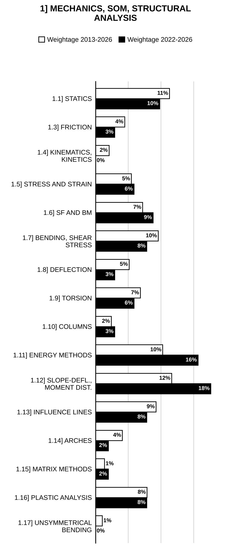
1.1] Statics: forces and equilibrium
19 questions
A frictionless pulley A as shown in the figure is supported by two bars AB and AC which are hinged at B and C to a vertical wall. A flexible cable, hinged at D, goes over the pulley and supports a load 30 kN at the other end E. The angles between the members are shown in the figure. Neglecting the size of the pulley, determine the forces in the bars AB and AC by drawing the free body diagram:
[Figure: Vertical wall with hinges at B (top), D (middle) and C (bottom). Frictionless pulley at A, to the right of the wall. Bar AB makes 60° with the wall at B; the cable DA makes 60° with the wall at D (measured from the upward wall direction); bar AC makes 30° with the wall at C; the angle between cable AD and bar AC at A is 30°. From the pulley the cable hangs vertically down to E carrying a load of 30 kN.] [2026/10m/1a]
Three bodies of weights 200 N, 800 N and 400 N are connected with inextensible strings, passing over the frictionless pulleys as shown in the figure. Using virtual work method, determine the force required to make the motion impending to the left. Take coefficient of friction for all the contacting surfaces as 0.30 except for the pulleys which are frictionless:
[Figure: Block of 200 N on an upper horizontal surface, pulled to the left by force ; a string from it passes over Pulley 1 at the top edge of a 45° incline (sloping down to the right) to the 800 N block resting on the incline; from the 800 N block a string passes over Pulley 2 at the foot of the incline to the 400 N block resting on a lower horizontal surface to the right.] [2026/10m/4a]
Draw the free body diagram of link ABCD and determine all reaction forces acting at A, B, C and D of the assembly shown in the figure. (All dimensions are in mm.)
[Figure: Two bent horizontal links above a fixed horizontal base (ground). Link ABCD (lower link): from pin A at its upper left end it drops 40 mm vertically and then runs horizontally to the right; it is pinned at B to a bracket fixed to the base, 80 mm to the right of A; it carries a ball (roller) C on its top surface 80 mm to the right of B, and rests on a ball (roller) D on the base 40 mm to the right of C. Upper link AE: pinned to link ABCD at A, it runs horizontally to the right above link ABCD, resting on ball C, and turns up vertically at its right end E, 40 mm to the right of D. A horizontal force of 480 N acts at E towards the right; E is 80 mm above the level of the lower link. Horizontal dimensions: A to B 80, B to C 80, C to D 40, D to E 40; vertical: A is 40 above the lower link, E is 80 above the lower link.] [2025/10m/1a]
A cantilever beam ABCD, as shown in the above figure, is carrying a uniformly distributed load of 10 kN/m between B & C and a clockwise moment of 50 kN-m at free end D. Draw the free body diagram for A, D and for the member BC only.
[Figure: Cantilever beam ABCD fixed at A and free at D; AB = 2 m, BC = 2 m, CD = 2 m. Portion AC is deeper, marked 2I; portion CD is shallower (step at C, top surface continuous), marked I. UDL 10 kN/m on the top of BC. Clockwise moment 50 kN-m at the free end D.] [2024/10m/1a]
Determine the forces in all the members of a pin-jointed truss shown in the figure below, with a vertical force of 20 kN and a horizontal force of 10 kN acting at :
[Figure: Pin-jointed truss ACBD. Supports: A hinged, B roller, A and B at the same level, AB = 3 m + 3 m = 6 m horizontally. Apex C is vertically above the mid-point of AB at a height of 4 m (2 m + 2 m). Joint D is vertically below C, 2 m above the level of AB (i.e. 2 m below C). Members: AC, BC, AD, BD and vertical CD. Loads at C: vertical (downward) force 20 kN and horizontal force 10 kN acting towards the right (towards B’s side).] [2022/15m/2a]
Determine the forces in members AC, DE and GH of the truss loaded and supported as shown in the figure below:
[Figure: Pin-jointed truss, top chord A–C–D–G–H horizontal with AC = CD = DG = GH = 2 m (span AH = 8 m); bottom chord B–E–F, 2 m below the top chord, with B vertically below C, E vertically below D and F vertically below G. Members: top chord AC, CD, DG, GH; bottom chord BE, EF; verticals CB, DE, GF; diagonals AB, CE, EG and FH. Hinged support at A, roller support at H (both at top-chord level). Vertical downward loads at the top-chord joints: 5 kN at A, 10 kN at C, 10 kN at D, 10 kN at G and 5 kN at H.] [2021/10m/1a]
A circular log of weight 1000 N and radius 18 cm is supported by a pair of brackets, one of which is shown in the figure below. Bar PN is hinged at ‘P’ and held by a string MN 67 cm long. To induce minimum tension at MN, determine the value of 2θ, as shown for equilibrium. Consider all contact surfaces smooth. Also find the value of minimum tension.
[Figure: A vertical wall with points M (upper) and P (lower). Bar PN is hinged to the wall at P and inclined upwards to the right; a horizontal string MN joins M on the wall to the upper end N of the bar. The log (circle, centre G) rests between the wall and the bar, touching the wall at Q (GQ horizontal) and the bar at J (GJ perpendicular to the bar). The line PG makes angle θ with the wall and angle θ with the bar, so the bar makes angle 2θ with the vertical wall.] [2021/10m/5a]
Determine the force in members GE, GC and BC of the truss shown in the figure below. Indicate whether the members are in tension or compression.
[Figure: Truss with bottom chord A–B–C–D, three panels of 4 m each (AD = 12 m); top chord G–E, with G vertically above B and E vertically above C, height 3 m. Members: AB, BC, CD, AG, GB, GE, GC, EC and ED. A hinged support at A, roller support at D. Loads: 1200 N vertically downward at C; 400 N horizontal to the right at E.] [2020/15m/2a]
Draw the free body diagram for lower and upper parts of the system. Calculate all reactions for the figure shown below.
[Figure: Two horizontal beams. Lower beam AC: end A is held by a hinge (pin) support attached to the ceiling above A; B is a hinged support below the beam, 0.3 m from A; the beam continues 0.5 m beyond B to its end C. Upper beam CE rests on the end C of the lower beam (point bearing at C) and spans to E, where it is pinned to a vertical wall (hinge shown as a small box with a dot). A vertical downward load of 5 kN acts at D on the upper beam. Horizontal dimensions: A–B 0.3 m, B–C 0.5 m, C–D 0.3 m, D–E 0.5 m.] [2018/10m/1a]
A lever is loaded as shown in the above figure. (i) Calculate the moment of force at Point . (ii) Calculate the amount of horizontal force to be applied at to produce the same amount of moment of force as calculated above. (iii) Calculate smallest amount of force to be applied at , to produce the same amount of moment of force as calculated in part (i). (iv) Calculate the distance of point on lever, where 1.20 kN vertical force to be applied to produce same amount of moment of force as calculated in part (i).
[Figure: Straight lever AB of length 1.0 m, end A at the bottom (pivot point, on a horizontal dashed reference line) and end B at the top right; the lever is inclined at 45° to the horizontal. A vertical downward force of 600 N acts at B.] [2017/10m/1d]
A rod AB 6 m long is held against sliding by a string AD. The rod weighs 10 kN. Determine the tension in the string AD assuming that all surfaces are smooth.
[Figure: Rod AB, 6 m long, with its lower end A on a smooth horizontal floor, inclined at 60° to the floor; the rod rests against the smooth top corner C of a vertical step/wall CD of height 4 m (C at the top, D at the foot on the floor), its upper end B projecting above C; a horizontal string AD (tension T) along the floor connects A to D] [2015/10m/1a]
Find the resultant of the force system acting on a lamina of equilateral triangle of sides 200 mm shown in Fig. 1(a). Also, find its direction and position with respect to .
[Figure: Fig. 1(a) – Equilateral triangular lamina ABC of side 200 mm, A at bottom left, C at bottom right, B at the apex. Forces: 50 kN at B acting upwards along the line CB produced (up and to the left, away from C); 60 kN acting along the line from A through the mid-point of BC, arrow pointing away from A (upwards to the right); 30 kN at C acting horizontally to the right along AC produced; 80 kN acting vertically downwards along the vertical line from B through the mid-point of AC (arrowhead below AC). No other labels or dimensions.] [2014/10m/1a]
Determine the forces and their nature in the members meeting at joint of the truss shown in Fig. 5(a).
[Figure: Fig. 5(a) – Truss ABCD of span 20 m: A (left) on a hinged support and C (right) on a roller support at the same level, AC = 10 m + 10 m. Apex B at mid-span, 6 m above A (dimensioned 3 m + 3 m); internal joint D vertically below B, 3 m above A. Members AB, BC, AD, DC and BD (no bottom chord AC). Loads at B: 32 kN acting vertically upwards and 24 kN acting horizontally to the right.] [2014/10m/5a]
Find the resultant of the force system acting on a lamina of equilateral triangle of sides 200 mm. Find also its direction and position w.r.t. point as shown in the figure. and are the mid-points of and respectively.
[Figure: Equilateral triangular lamina ABC of side 200 mm, A at bottom left, C at bottom right, B at the apex; D is the mid-point of BC and E the mid-point of AC (equal-length tick marks on AE = EC and BD = DC). Forces: 50 kN at B acting along the line CB produced (upwards and to the left, away from C); 60 kN at D acting along the line AD produced (upwards to the right, away from A); 30 kN at C acting horizontally to the right along AC produced; 80 kN acting vertically downwards along the vertical line through B and E (shown below E).] [2013/10m/1a]
Draw free body diagram (FBD) of the whole system as shown in the figure. Neglecting self-weight of its parts , , and , draw FBDs of individual parts also. The wheel at is frictionless.
[Figure: Triangular frame ABC: vertical member AB (B at top), inclined member BC running down from B to C, and horizontal member AC. A rests on a roller support; C is a hinged (pin) support at the same level. A frictionless wheel (pulley) D is pinned on member AC near A. A rope is attached at E on AB, a little above A, runs horizontally to the top of the wheel D, passes round the wheel and hangs vertically down from it carrying a block of weight W. No dimensions are given.] [2013/10m/2a]
Two equal cylinders, and , each weighing 1000 N are placed in a box as shown in the figure. Neglecting friction between the cylinders and the box, estimate reactions at , and .
[Figure: Rectangular box with vertical side walls and a horizontal bottom. Cylinder E (lower, left) touches the left wall at A and the bottom at B; cylinder F (upper, right) rests on E and touches the right wall at C. The line joining the centres of E and F is inclined at 45° to the horizontal. No other dimensions are given.] [2013/10m/4a]
A rigid jointed tower frame, as shown in Fig. 4, has hinged support at and fixed support at . The pinnacle carries a vertical load of 80 t. Calculate all components of reactions at and .
[Figure: Fig. 4 – Symmetrical A-shaped tower frame: two inclined legs A–B–D–F (left) and A–C–E–G (right) meeting at the apex A, which carries a vertical load of 80 t; horizontal member BC connects the legs 8 m below A; points D and E on the legs 4 m below BC, each marked with a solid dot (the same symbol as at the hinge F); supports F and G on the ground 4 m below D and E (total height 16 m = 8 m + 4 m + 4 m). F is a hinged support (labelled “Hinge”) and G is a fixed support; F and G are each 4 m from the vertical centre line (base width 8 m)] [2010/30m/3a]
A smooth right circular cylinder of radius 0.5 m rests on a horizontal plane and is kept from rolling by an inclined string of length 1.0 m. A prismatic bar of length 1.5 m and weight 125 N is hinged at point and leans against the cylinder as shown in the figure below. Find the tension that will be induced in the string .
[Figure: A smooth cylinder with centre C resting on a horizontal plane. Point A is on the plane to the left of the cylinder. String AC runs from the hinge A to the centre C of the cylinder. A prismatic bar is hinged at A, inclined upwards to the right, and rests tangentially on the top-left of the cylinder, its upper end projecting beyond the point of contact] [2009/12m/1a]
Find forces in all members of the truss shown, due to a concentrated load 100 kN at C.
[Figure: Truss inscribed in a semicircle (shown dashed) of radius a with centre O. A and E are the ends of the horizontal diameter; A is a hinged (pinned) support and E is a roller support. Joints B, C, D lie on the semicircle, C at the crown vertically above O; radial members OB and OD make 45° with the horizontal, so the angles at O between OA–OB, OB–OC, OC–OD and OD–OE are each 45°. Members: AO and OE (bottom chord, length a each), OB, OC, OD (radial, length a each), and chords AB, BC, CD, DE. Vertical load 100 kN downward at C]
[2004/12m/1b]
1.2] Moments of area and mass moment of inertia
2 questions
Determine the centroid of the Angle section shown in Fig. 1.
[Figure: Fig. 1 – Angle section (all dimensions in mm). Overall width 80 (top, dimensioned 40 + 40), overall height 80. Horizontal top flange 80 wide and 20 deep; vertical leg on the left 20 wide running down the full height of 80. The inner corner is chamfered: from the underside of the flange at 40 from the left edge (20 below the top) a sloping line runs down to the inner face of the leg (20 from the left edge) at 40 below the top. Right-hand dimensions from the top: 20, 20, 40 (total 80); bottom dimension of leg: 20] [2010/10m/1a]
A composite beam of cross-sectional dimensions is shown in the figure below. The upper 150 mm × 250 mm part is concrete, and the lower 150 mm × 10 mm part is strap steel, . Locate the centroid and calculate the second moment of area about the horizontal centroidal axis of the composite section.
[Figure: Rectangular section 150 mm wide; upper concrete part 250 mm deep; lower hatched steel strap 10 mm deep across the full 150 mm width] [2009/12m/1b]
1.3] Static friction
7 questions
Three bodies of weights 200 N, 800 N and 400 N are connected with inextensible strings, passing over the frictionless pulleys as shown in the figure. Using virtual work method, determine the force required to make the motion impending to the left. Take coefficient of friction for all the contacting surfaces as 0.30 except for the pulleys which are frictionless:
[Figure: Block of 200 N on an upper horizontal surface, pulled to the left by force ; a string from it passes over Pulley 1 at the top edge of a 45° incline (sloping down to the right) to the 800 N block resting on the incline; from the 800 N block a string passes over Pulley 2 at the foot of the incline to the 400 N block resting on a lower horizontal surface to the right.] [2026/10m/4a]
In the figure shown below, a strong-box of mass 85 kg rests on a floor. The static coefficient of friction for the contact surface is 0.25. What is the largest force, ‘F’ and the highest position, ‘h’ for applying this force, that will not allow the strong-box to either slip on the floor or to tip?
[Figure: Rectangular strong-box resting on a horizontal floor; base width 0.70 m. A horizontal force F acts towards the right on the left vertical face at height h above the floor. The weight W acts vertically downward through the centre of the box.] [2023/10m/1c]
Blocks A and B are connected through a cord and rest on the inclined planes as shown in the figure below. What is the tension in the cord, if the friction at block A reaches the maximum value? Assume that pulley at C is frictionless. Block A weighs 300 N and Block B weighs 400 N.
[Figure: Two inclined planes meeting at an apex C carrying a frictionless pulley: block A (300 N) on the left plane inclined at 60° to the horizontal, ; block B (400 N) on the right plane inclined at 30° to the horizontal, ; the blocks are connected by a cord passing over the pulley at C.] [2020/10m/5a]
The coefficient of static and kinetic friction between the 200 kg block and inclined plane shown in the figure below are 0.3 and 0.2 respectively. Determine (i) the friction force ‘F’ acting on the block when ‘P’ is applied with a magnitude of 400 N to the block at rest. (ii) the force ‘P’ required to initiate motion up the incline from rest. (iii) the friction force ‘F’ acting on the block if P = 1600 N.
[Figure: Block resting on a plane inclined at 20° to the horizontal; force P applied to the block, directed upwards at 30° to the inclined plane (measured from the line of the incline).] [2019/10m/5a]
In Figure 5(d), an inclined plane is kept at an angle of 45° from horizontal plane at the bottom edge of a smooth wall. A uniform ladder of length and mass M rests on the inclined plane against the wall such that it is perpendicular to the incline. What is the minimum coefficient of friction necessary so that the ladder does not slip on the incline?
[Figure: Figure 5(d) – Smooth vertical wall on the left; an inclined plane rising to the right from the foot of the wall at 45° to the horizontal; a ladder with its upper end against the wall and its lower end resting on the inclined plane, the ladder perpendicular to the incline (right-angle mark at the contact)] [2016/10m/5d]
A uniform ladder of length 7 m rests against a vertical wall with which it makes an angle of 45 degrees. The coefficient of friction between the ladder and the wall is , and between the ladder and the horizontal floor is . If a man weighing half as that of the ladder ascends it, how high will he be when the ladder just starts to slip? [2014/10m/4a]
What is the maximum height of a step in the figure so that a force will roll a cylinder of radius weighing over the step with no slippage at all. The coefficient of static friction is .
[Figure: Cylinder of radius R resting on a horizontal floor against a step of height x (step to the right of the cylinder). A horizontal force P acts to the right at the top of the cylinder. The vertical diameter is marked R + R.] [2013/10m/3a]
1.4] Kinematics and kinetics
7 questions
A particle moves from the origin, in the x-y plane so that at any time ‘’ its acceleration along the ‘’ and ‘’ axes are and . At , its velocity is 3 m/sec entirely along the x-axis. Find the equation to the path of the particle. Also find the minimum velocity of the particle. [2019/10m/1a]
For the system shown in Figure 1(c), a small block of mass m and a smooth irregular shaped block of mass M, both free to move, are placed on a smooth horizontal plane. Find the minimum velocity () to be imparted to the smaller block so that it reaches the highest point of the larger block.
[Figure: Figure 1(c) – Smooth horizontal plane; on the left a small block of mass m moving to the right with velocity v; to its right a smooth hump-shaped (irregular) block of mass M resting on the plane, its highest point at height h above the plane] [2016/10m/1c]
A particle moves on a vertical line with an acceleration . At t = 2 sec, its displacement is 8 m and velocity is 6 m/s. Determine its displacement, velocity and acceleration at time t = 4 sec. a = acceleration and v = velocity. [2015/10m/5b]
Three bodies , and of masses 50 kg, 30 kg and 20 kg respectively are under a force of 5 kN as shown. Calculate the force transferred between and , and . Assume all are frictionless surfaces.
[Figure: Three blocks resting side by side in contact on a horizontal frictionless (hatched) surface, from left to right: A (largest), B (smaller), C (smallest); a horizontal force of 5 kN acts towards the right on the left face of A, pushing the three blocks] [2012/12m/1b]
A body of mass 1000 kg is acted upon by a force of 80 Newtons which increases uniformly until it becomes 100 Newtons in 4 minutes. If motion starts from rest in the direction of force, find the velocity of the body at the end of 3 minutes from the start and the distance traversed. [2011/12m/1a]
A railway truck is loaded so that the pressure on each wheel is 5500 kg weight and the centre of gravity of the loaded truck is 1.5 metres above the rails. The centre-to-centre distance of the wheels on an axle is 1.75 metres. Find the pressure on the inner and outer rails when the truck is going round a curve of 440 metres radius at 48 km/hour. . [2011/30m/2a]
Three 5 kg masses attached to a light rod ABCD are spun on a frictionless horizontal plane at 600 rpm (10 Hz) about a pinion. What is the maximum force induced in the rod due to spinning?
[Figure: Side view: a vertical pinion shaft on the left (rotation shown by a curved arrow about its vertical axis); the light horizontal rod ABCD is attached to the pinion at its end D and lies on a frictionless horizontal surface (hatched), with the labels C, B, A below the masses. Three equal masses (5 kg each, drawn as small circles on the rod) are at C, B and A. Dimensions measured along the rod from the pinion axis: pinion axis to C = 0.5 m, C to B = 0.5 m, B to A (end of rod) = 0.5 m, i.e. the masses are at radii 0.5 m, 1.0 m and 1.5 m] [2004/12m/1a]
1.5] Simple stress and strain
10 questions
A T-section beam is constructed by gluing two pieces of wood together as shown in the figure. The maximum stress in the glue joints is to be limited to 2 MPa in tension and maximum shear stress is to be limited to 1.7 MPa. (i) Determine the stress components on element at point ‘P’. Point ‘P’ is located at glued joint. (ii) Determine principal stresses at point ‘P’. (iii) Show these stresses on properly oriented 2-D elements. (iv) Determine the maximum value for load ‘w’.
[Figure: (a) Simply supported beam AB, span 2 m, hinge at A, roller at B; UDL w (N/m) over the whole span; a couple of 4w (N-m) applied at A (curved arrow, anticlockwise). (b) Cross-section: inverted T – a horizontal piece 150 mm wide × 50 mm deep at the bottom (flange) and a vertical piece 50 mm wide × 150 mm high glued on top of it at the centre (web); point P on the glued joint at the base of the web, on its centre line.] [2025/20m/2a]
An aluminium tensile specimen has a diameter of 30.50 mm and a gauge length 275 mm. If the force of N elongates the gauge length by 1.28 mm, determine the Poisson’s ratio and the modulus of elasticity. Also, determine by how much the force causes the diameter of the specimen to contract. Assume shear modulus and yield strength . [2023/10m/1a]
A rod shown in the figure below is subjected to a force of 95 kN. Determine the diameter of the portion (2), if the stress there is not to exceed . Also, determine the axial deformation of the rod. Use :
[Figure: Stepped circular rod in axial tension, pulled by 95 kN at each end (arrows pointing outward). From left to right: portion (1) 50 mm dia, length 100 mm; portion (2) diameter , length 50 mm; portion (3) 85 mm dia, length 100 mm; portion (4) 50 mm dia, length 50 mm.] [2022/10m/1a]
The fixed-end bar ABCD consists of three prismatic segments as shown in the figure. The end segments AB and CD have cross-sectional area and length 300 mm. The middle segment has cross-sectional area and length 500 mm. Two axial loads and are acting in the bar as shown in the figure. Young modulus E is same for all three segments. (i) Determine the reaction forces at fixed supports. (ii) Determine the compressive axial force in the middle segment.
[Figure: Horizontal bar ABCD fixed between two walls at A (left) and D (right): AB = 300 mm (smaller section), BC = 500 mm (larger section), CD = 300 mm (smaller section). Axial load applied at B acting to the right (towards C); axial load applied at C acting to the left (towards B).] [2021/10m/5c]
Three metal cubes are arranged as shown in Figure 6(a). The central metal cube is subjected to a uniform compressive stress of 1000 . Calculate the volumetric strain of cube 2, if displacement is restrained about the x-axis. (i) (ii) (iii) (iv) (v) (vi)
[Figure: Figure 6(a) – Three cubes ①, ②, ③ placed side by side along the x-axis on a rigid base, between a rigid face on the left and a rigid face on the right; cube 1: ; cube 2: ; cube 3: ; uniform compressive stress acting downward on the top of the central cube 2 only; axes x (horizontal), y (vertical), z (out of plane)] [2016/20m/6a]
A circular copper bar is carrying a tensile load of 200 kN as shown in Figure 8(c). Calculate the displacement of point B of the copper bar. Cross-sectional area of the copper bar = 5000 ; Cross-sectional area of each of the steel bars = 5000 ; Length of the copper bar = 3.0 m; Length of each of the steel bars = 1.0 m; GPa, GPa.
[Figure: Figure 8(c) – A rigid plate (end A at its left) is supported on two vertical steel bars, one on each side, each 1.0 m long, standing on a fixed support below the plate; a copper bar hangs from the middle of the rigid plate, passing down through an opening in the fixed support, 3.0 m long from the plate to its lower end B; tensile load 200 kN applied downward at B] [2016/10m/8c]
A vertical steel cylinder storage tank of 30 m diameter is filled up to a depth of 15 m with gasoline having relative density of 0.74. Determine the thickness required for the wall plate using a factor of safety of 2.5. Take MPa. Ignore the localized bending effects, if any. Use working stress method of design. [2014/10m/3a(i)]
A steel rod of length 300 mm and diameter 30 mm, is subjected to a pull ‘P’ while the temperature is 100°C. If the total extension of the rod is 0.40 mm, calculate the magnitude of ‘P’. Take ‘’ for steel = per °C and . [2011/12m/1b]
What are the strength theories for yielding and fracture of materials? State the theory more suited for (i) mild steel, (ii) concrete. [2004/12m/1c]
A solid steel rod of length 2 m diameter 20 mm vertically hangs from the ceiling and has a collar firmly attached to it. Above the collar an annular rubber washer of 40 mm thickness having a stiffness is placed. Determine maximum stress in the rod caused by a mass of 5 kg falling through a height of 1.2 m. [2004/20m/2a]
1.6] Shear force and bending moment
10 questions
Draw the bending moment diagram and shear force diagram for the beam ABCD. The beam supports a point load of 12 kN as shown in the figure:
[Figure: Bent cantilever ABCD fixed at A (wall on the left): AB horizontal, 2 m; BC vertical downwards, 0.6 m; CD horizontal to the right, 0.3 m; vertical point load 12 kN downwards at the free end D.] [2026/10m/1b]
The given figure shows the shear force diagram for a beam ABCDEF. The beam has hinge support at A and at one more point. Draw the load diagram and bending moment diagram (BMD) for this beam, indicating the shape of BMD between two successive points. Also show the point of contraflexure (if any):
[Figure: SHEAR FORCE DIAGRAM for beam ABCDEF: AC = 4 m, CD = 3 m, DE = 2 m, EF = 2 m. Shear force is –10 kN at A and varies linearly to zero at B and to +2 kN at C; constant +2 kN from C to D; jumps at D to +7 kN, constant +7 kN from D to E; drops at E to –2 kN, constant –2 kN from E to F; returns to zero at F.] [2026/20m/3b]
Draw the shearing force and bending moment diagrams for the beam loaded as shown in the figure below.
[Figure: Beam C–A–D–E–B–F. Hinged support at A, roller support at B; C (left end) and F (right end) are free. Distances: CA = 1 m, AD = 2 m, DE = 1 m, EB = 2 m, BF = 2 m. UDL 2 kN/m over CD (from C to D, 3 m). Vertical point load 8 kN at D (downward). Clockwise couple 6 kN-m at E. Vertical point load 4 kN at F (downward).] [2023/15m/2a]
For the beam shown in the figure below (i) Compute the support reactions. (ii) Write the shear force (V) and bending moment (M) value(s) at salient points as indicated in the table.
| x | A | B | C | D | E | F |
| V | ||||||
| M |
(iii) Draw the shear force diagram (SFD) indicating the nature of graph. (iv) Draw the bending moment diagram (BMD) indicating the nature of graph. Sign conventions for SFD and BMD are as follows:
[Figure: Sign conventions: +V shown as a downward arrow on the left face and an upward arrow on the right face of an element; +M shown as moments that bend the element concave upwards (sagging: clockwise on the left face, anticlockwise on the right face).]
[Figure: Beam A–B–C–D–E–F with an overhang beyond F. Left end A is free; hinged support at B, AB = 0.5 m; BC = 1 m; CD = 2 m; DE = 1.5 m; roller support at E; EF = 0.5 m; the beam extends a further 0.5 m beyond F to the free right end. Loads: UDL 25 kN/m over AB; concentrated couple 300 kN-m at C (anticlockwise as drawn); vertical point load 50 kN at D; vertical point load 40 kN at F.] [2021/15m/6b]
An 8 m long beam is loaded with a uniformly distributed load, w/m over the entire span. The beam is supported at supports A and B as shown in Figure (a). Bending moment diagram for the beam is shown in Figure (b). Determine the value of udl, w and draw the shear force diagram. Also determine the maximum bending moment in the beam and its point of application.
[Figure (a): Beam 8 m long carrying a UDL w/m over its entire length, supported at the left end and at 6 m from the left end, with an overhang of 2 m. Figure (b): Bending moment diagram – positive (sagging) parabola over the 6 m span, crossing zero and becoming negative (hogging) towards the right support, where the hogging moment is 30 kN-m; negative curve falling to zero at the free end of the 2 m overhang.] [2020/10m/5c]
Bending moment diagram for a beam carrying uniformly distributed load has been shown below. Bending moment diagram curve is parabolic and follows the equation in AB and DE portion. Calculate the values of load and plot loading and shear force diagram.
[Figure: Bending moment diagram of a beam ABCDE: AB = 2.0 m, BD = 6.0 m with C at its centre (3.0 m from C to D), DE = 2.0 m. Over the overhangs AB and DE the moment is negative (hogging), following the parabolic curve from zero at A and at E to 20 kN-m at B and at D. Between B and D the diagram is a parabola, positive (sagging) in the middle with a maximum of 25 kN-m at C, and −20 kN-m at B and D.] [2018/15m/4c]
Calculate bending moment and shear force and plot their variation for the frame shown in the above figure.
[Figure: Frame ABCD: vertical column AB of height 1.5 L with A at the bottom and B at the top; horizontal beam BCD extending to the right from B. A is a roller support bearing against a vertical wall (on the right of A, i.e. providing a horizontal reaction); C is a hinged (pin) support under the beam at a distance L from B. Vertical downward load W at the mid-point of BC (L/2 from B) and vertical downward load W at the free end D, which is L/2 beyond C (dimensions L/2 – L/2 – L/2).] [2017/10m/1e]
Draw the bending moment diagram and shear force for the beam as shown in the figure.
[Figure: Beam ADBC: hinged support at A, roller support at B, overhang BC. AD = 2 m, DB = 2 m, BC = 2 m. Point load 10 kN at D; uniformly distributed load 2 kN/m over the overhang BC.] [2013/10m/5b]
Draw the bending moment and shear force diagram of the beam as shown. = constant.
[Figure: Beam AEBCFD, total length 10 m: A fixed (left end); E at 1 m from A carrying point load 2 kN; B at 3 m from A is an internal hinge; BC = 4 m carrying a uniformly distributed load of 4 kN/m over its length; C is an internal hinge; F at 1 m from D carrying point load 2 kN; CD = 3 m; D fixed (right end)] [2012/15m/3b]
A beam of uniform cross-section resting on two supports ‘b’ m apart has an equal overhang of ‘a’ m on either end. Determine the ratio of b/a when the magnitude of mid span bending moment is equal to the magnitude of support bending moment due to its own weight. For this condition, draw the bending moment diagram, locate contraflexure points. [2004/20m/2b]
1.7] Bending and shear stresses in beams
16 questions
A T-section beam is constructed by gluing two pieces of wood together as shown in the figure. The maximum stress in the glue joints is to be limited to 2 MPa in tension and maximum shear stress is to be limited to 1.7 MPa. (i) Determine the stress components on element at point ‘P’. Point ‘P’ is located at glued joint. (ii) Determine principal stresses at point ‘P’. (iii) Show these stresses on properly oriented 2-D elements. (iv) Determine the maximum value for load ‘w’.
[Figure: (a) Simply supported beam AB, span 2 m, hinge at A, roller at B; UDL w (N/m) over the whole span; a couple of 4w (N-m) applied at A (curved arrow, anticlockwise). (b) Cross-section: inverted T – a horizontal piece 150 mm wide × 50 mm deep at the bottom (flange) and a vertical piece 50 mm wide × 150 mm high glued on top of it at the centre (web); point P on the glued joint at the base of the web, on its centre line.] [2025/20m/2a]
Cross-section of an axially loaded compression member is shown in the above figure. This compression member was to be loaded at centre ‘O’ of the Section. Due to mistake this was loaded at point ‘P’ by a concentrated load of 500 kN. Find out the stresses at points A, B, C and D of the Section.
[Figure: Square cross-section ABCD, 600 mm × 600 mm (A top-left, B top-right, C bottom-right, D bottom-left; drawn slightly skewed), with centroidal axes through the centre O. The 500 kN load acts at point P, located 100 mm from O parallel to AB (towards side BC) and 100 mm from O parallel to BC (towards side AB), i.e. in the quadrant nearest corner B.] [2024/10m/1b]
A cantilever beam ABC as shown in the above figure is having a total span of 2.0 m. The maximum safe allowable bending stress is 7500 kN/m² for the material. Find the maximum safe uniformly distributed load which this beam can carry. What will be the maximum shear stress at support A for the obtained safe UDL? (Neglect the self weight of beam)
[Figure: Cantilever ABC fixed at A, free at C; AB = 1.0 m, BC = 1.0 m, top surface continuous with a step in depth at B. Portion AB: rectangular section 0.2 m wide × 0.45 m deep (Section ①–① taken in AB). Portion BC: square section 0.2 m × 0.2 m (Section ②–② taken in BC).] [2024/20m/2a]
A small T-beam is used in an inverted position to span 400 mm. Find the value of P if due to the application of three forces shown in the figure, the longitudinal gauge at A registers a compressive strain of . Also determine the maximum bending stresses in the beam. Given: GPa.
[Figure: Simply supported beam of span 400 mm, hinged at the left end and on a roller at the right end. Downward loads: P at 100 mm from the left support, P at 200 mm, and 3P at 300 mm; section A-A at 250 mm from the left support (midway between the second P and 3P). Section A-A: inverted T – a flange 12 mm wide × 4 mm thick at the bottom and a web (stem) 4 mm wide rising 12 mm above the flange (overall depth 16 mm); strain gauge A on the side of the stem 3 mm below its top.] [2020/15m/4a]
A tapering chimney of hollow circular section is 40 m high. Its external diameter at the base is 3.0 m and at the top it is 2.0 m. It is subjected to wind pressure of of the projected area. If the weight of the chimney is 5000 kN and internal diameter at the base is 1.2 m, determine the maximum and minimum stress intensities at the base. [2019/15m/2c]
Channel section shown in the figure is carrying water to full depth. Permissible stress in channel material is limited to 200 MPa. Channel will be simply supported at its ends. Calculate this support spacing for a factor of safety 1.5 to the loads. Neglect self-weight of channel. Unit weight of water is .
[Figure: Open rectangular (U-shaped) channel cross-section: overall width 1020 mm, overall depth 1010 mm; side walls 10 mm thick and base 10 mm thick; water level at the top of the walls.] [2018/10m/5b]
Calculate maximum bending stress and shear stress at the fixed end of a cantilever beam as shown in the above figure. Also sketch the variations of bending stress and shear stress at fixed end. Beam has a uniform thickness of 50 mm. Beam has a depth of 200 mm at free end and 300 mm at fixed end.
[Figure: Tapered cantilever 1.0 m long, fixed at the left end (depth 300 mm) and tapering symmetrically about its axis to a depth of 200 mm at the free right end, where a vertical downward load of 100 kN acts.] [2017/15m/7c]
Sketch the variation of shear stresses for the cross-sections of the beams shown in Figure 5(a) at the point of maximum shear force.
[Figure: Figure 5(a) – Four beam cross-sections (no dimensions given), each with horizontal and vertical centroidal axes: (i) cross-shaped (+) section – a vertical rectangle crossed at mid-height by a horizontal rectangle; (ii) H-section – two vertical rectangular flanges joined at mid-height by a horizontal web; (iii) square section with a central circular hole; (iv) square section turned through 45° (diamond, diagonal horizontal)] [2016/10m/5a]
A simply supported beam of homogeneous cross-section and material is subjected to axial and transverse loads as shown in Figure 8(a)(ii). Calculate the total stresses at points ① and ② of the section C as shown in the figure.
[Figure: Figure 8(a)(ii) – Simply supported beam AB, span 10.0 m, supports at A and B; UDL 10 kN/m over the whole span (including self-weight of beam); axial compressive force 100 kN applied at each end along the centroidal axis (pushing inwards at A and B); section C at mid-span, 5.0 m from A. Section at C: rectangle 100 mm wide × 200 mm deep; point ① at the top left corner, point ② at the bottom right corner] [2016/10m/8a(ii)]
Two wheels, placed at a distance of 2.5 m apart, with a load of 200 kN on each of them, are moving on a simply supported girder (I-section) of span 6.0 m. The top and bottom flanges of the I-section are of 200 × 200 mm and the size of web plate is 800 × 6 mm. If the allowable bending compressive, bending tensile and average shear stresses are 110 MPa, 165 MPa and 100 MPa respectively, check the adequacy of the section against bending and shear stresses, self weight of the girder may be neglected. [2015/20m/2b]
A beam has a cross-section shown in figure. It is subjected to a vertical shear force of 10 kN at a given section. Determine the shear stress distribution on the section.
[Figure: Symmetrical cross-shaped (+) section: a central vertical web 50 mm wide and 200 mm deep overall, crossed at mid-height by a horizontal flange 250 mm wide (100 mm + 50 mm + 100 mm) and 100 mm deep (50 + 50 about the horizontal centroidal axis); the web projects 50 mm above and 50 mm below the flange (depth dimensions 50 mm, 50, 50, 50)] [2015/15m/6a]
Compare the moments of resistance for a given maximum bending stress of a beam of square section placed (i) with two sides vertical and (ii) with a diagonal vertical. The bending in each case is parallel to vertical plane. [2012/12m/1a]
A cantilever beam of cross-section 50 mm × 100 mm is subjected to a compressive force parallel to the longitudinal axis of the beam at the free end. The point of application of the load is at 10 mm above the bottom surface on the vertical centroidal axis. The span of the beam is 4 m. Calculate the maximum stresses in the beam. [2012/15m/2b]
A beam of length 5 m and of uniform rectangular section is supported at its ends and carries a uniformly distributed load over the entire length. Calculate the depth of the section if the maximum permissible bending stress is and central deflection is not to exceed 12 mm. Assume the value of . [2010/10m/1b]
A timber beam of rectangular section of length 8 m is simply supported. The beam carries a uniformly distributed load of 12 kN/m run, over the entire length and a point load of 10 kN at 3 metre from the left support. If the depth is two times the width and stress in the timber is not to exceed , find the suitable dimensions of the section. [2010/30m/4a]
As shown in the figure, an I-section is made using 3 wooden planks of dimensions 150 mm × 10 mm to give a total depth of 170 mm. The glue that is used to join the planks at the joint is having a permissible shear stress of after it is cured. Check whether the section is safe at the joint to withstand, when it is used as a cantilever of span 1 m, due to a concentrated load of 1 kN applied at the free end.
[Figure: I-section made of three planks: top flange 150 mm × 10 mm, bottom flange 150 mm × 10 mm, vertical web 10 mm thick and 150 mm deep between the flanges; total depth 170 mm; glue at the two web–flange joints (labelled Glue)] [2009/20m/3a]
1.8] Deflection of beams
9 questions
A horizontal steel bar of 60 mm diameter is rigidly tied at each end, the ties being 1.25 m apart. A rigid bracket is fixed to the middle of the bar. Determine the maximum radial length of the bracket at which a vertical load of 1400 N can be suspended, if the deflection of the load is not to exceed 0.5 mm. Take ; . [2025/10m/4b]
A 10 mts long steel pipe is simply supported at both ends. It is having 500 mm external diameter and 20 mm thickness. It is carrying a total uniformly distributed load of 100 kN/m (including the self weight). Calculate the maximum deflection of the pipe. Take E = 200 GPa. [2024/10m/3c]
Using moment area method, find the slopes and deflection at ‘B’ for the beam shown in the figure below. Point ‘B’ is a hinge.
[Figure: Beam ABCD with fixed support at A (left end, built into a wall), an internal hinge at B, and a simple (hinged) support at D (right end); AB = BC = CD = L (total length 3L). Vertical downward point load W at C.] [2021/15m/2a]
Using conjugate beam method, for the beam shown below, find the slopes and deflections at ‘A’, ‘B’, ‘C’ and ‘D’. Given: and . Neglect the weight of the beam.
[Figure: Simply supported beam AB of span 30 m (supports at A and B, reaction arrows upward), made of three segments of 10 m each: A to C moment of inertia I, C to D 3I, D to B 2I. Point loads 75 kN at C (10 m from A) and 150 kN at D (20 m from A).] [2019/20m/6a]
A cantilever beam carries a uniformly distributed load over its entire length. Maximum possible deflection at the free end ‘B’ is limited to 40 mm. Calculate the magnitude of maximum possible uniformly distributed load (dead load + live load) for a combined factor of safety of 1.5 on this beam. Size of beam = 200 mm × 400 mm.
[Figure: Cantilever AB of span 5.0 m, fixed at A, free at B, carrying a uniformly distributed load over its whole length; rectangular cross-section 200 mm wide × 400 mm deep.] [2018/10m/5a]
Determine the slope at A, vertical deflections at B and mid span using the moment-area theorem. Take EI = Const.
[Figure: Simply supported beam AD of span 6 m, supports at A and D; point loads 20 kN at B (2 m from A) and 20 kN at C (2 m from D); O is the mid-span point between B and C (BO = OC = 1 m)] [2015/15m/3a]
A beam of length 5 m and of uniform rectangular section is supported at its ends and carries a uniformly distributed load over the entire length. Calculate the depth of the section if the maximum permissible bending stress is and central deflection is not to exceed 12 mm. Assume the value of . [2010/10m/1b]
For the beam shown in the figure below, find the fixed moment at ends and , using conjugate beam method. is constant.
[Figure: Beam AB fixed at both ends A and B, span 10 m; point load 50 kN at 3 m from A; point load 75 kN at 4 m further (7 m from A, 3 m from B)] [2009/12m/1c]
In a structure, a beam is loaded with a concentrated load of 100 kN acting at 3 m from one of the supports on a span of 5 m. The beam may be assumed to be simply supported. If the deflection under the load is not to exceed 6 mm, find the depth of the beam, assuming it to be of rectangular cross-section. Assume the width of the beam as 200 mm and . [2009/20m/4b]

Preparing for Prelims too?
Our UPSC Prelims Topic-wise PYQ eBook covers every Prelims question with detailed explanations, so you can see exactly where UPSC asks from.
View the BookDownload Free Sample1.9] Torsion of shafts
8 questions
A horizontal steel bar of 60 mm diameter is rigidly tied at each end, the ties being 1.25 m apart. A rigid bracket is fixed to the middle of the bar. Determine the maximum radial length of the bracket at which a vertical load of 1400 N can be suspended, if the deflection of the load is not to exceed 0.5 mm. Take ; . [2025/10m/4b]
A solid steel shaft of diameter 65 mm is to be designed using an allowable shear stress and an allowable angle of twist per unit length per metre. Determine the maximum permissible torque that may be applied to the shaft. Take shear modulus as 80 GPa. [2023/10m/1b]
A solid circular shaft is subjected to a bending moment of N-m and a twisting moment of 13 kN-m. In a simple uniaxial tensile test of the same material, it gave the following data: , , Factor of safety (FOS) = 3, . Determine the least diameter required using the following: (i) Maximum principal stress theory (ii) Maximum shear stress theory. [2022/15m/2c]
A 1 m long hollow shaft is to transmit a torque of 400 N-m. The outer diameter of the shaft must be 25 mm to fit existing attachments. The relative rotation of the two ends of the shaft is limited to 0.375 rad. The shaft can be made of either titanium alloy or aluminium. Using the data given in the table below, determine the maximum inner radius to the nearest millimeter of the lightest shaft that can be used for transmitting the torque.
| Material | Shear Modulus G (GPa) | Maximum Shear Stress (MPa) | (density) () |
| Titanium alloy | 36 | 450 | 4.4 |
| Aluminium | 28 | 150 | 2.8 |
[Figure: Hollow circular shaft, length 1 m, outer diameter 25 mm.] [2021/20m/8c]
Calculate the maximum shear stress in a hollow circular shaft having 300 mm external diameter and 150 mm internal diameter. This shaft is subjected to a twisting moment of 4 kN-m. If modulus of Rigidity , calculate the twist for a length of 20 times the external diameter of shaft. [2017/10m/5e]
A horizontal shaft 12 m in length is fixed at its ends. When viewed from its left end, axial couples of 50 kNm clockwise and 75 kNm counterclockwise act at 5 m and 9 m from the left end respectively. Determine the end fixing couples and the position where the shaft suffers no angular twist. [2015/10m/5c]
A solid circular shaft of diameter is loaded with torque as shown in Fig. 4(b). Plot the diagrams showing the variation of and .
[Figure: Fig. 4(b) – Solid circular shaft fixed to a wall at its left end and free at the right end, total length 6 m, divided by vertical lines into three lengths from the wall: x m, (4–x) m and 2 m. Torques shown as curved arrows: 4 kN-m drawn on the first length (x m), 8 kN-m drawn on the second length ((4–x) m), both curved arrows with the arrowhead at the top; 4 kN-m applied at the free right end, drawn as a couple with the upper arrow pointing up and to the right and the lower arrow pointing down and to the left.] [2014/20m/4b]
Design two solid circular shafts to transmit 200 HP each without exceeding a shearing stress of 70 MPa. One of these operates at 20 RPM and the other at 20,000 RPM. Give your inference about the final results from the view point of economy. Do you have any other suggestion to improve the economy further? [2013/10m/1b]
1.10] Elastic stability of columns
7 questions
A straight bar of alloy is mounted in a strut-testing machine with both ends pin jointed and loaded axially till it buckles. Using Euler’s formula, calculate the maximum central deflection before the alloy material attains the yield point at . Take bar length = 2.0 m, cross-section of the bar as 20 mm × 15 mm and modulus of elasticity as . [2026/15m/2b]
Two bars of 50 mm dia are connected as shown in the above figure. Find the maximum load that can be applied. .
[Figure: Two bars forming a symmetrical inverted V: each bar is inclined at 45° to the horizontal and pinned to a support at its lower end (the two supports at the same level); the bars meet at the apex, 3 m above the supports, where a vertical downward load P is applied.] [2017/10m/5d]
A long column is initially straight and hinged at both ends. Consider, least moment of inertia I, Young’s modulus E, homogeneous material and centre-to-centre distance of hinge support L. Prove that the critical load for the column will be . [2016/10m/8a(i)]
Calculate the maximum load that can be applied on the frame as shown. Yield stress = 320 MPa and GPa.
[Figure: Two-member frame ACB: A is a pinned support on the left; member AC rises from A at 60° to the horizontal to joint C; member CB descends from C to a pinned support B on the right, inclined at 30° to the horizontal (B lies below the level of A); C is 4 m above the horizontal (dashed) line through A; vertical load P applied downward at C. Cross-section of the members (“C/S of the members”): hollow rectangular box section, outer dimensions 50 mm wide × 60 mm deep, inner dimensions 40 mm wide × 50 mm deep] [2012/15m/4a]
A cast iron column of circular section of 20.0 cm external diameter and 2.0 cm thickness and of height 4.0 metres is required to carry 15.0 kN at an eccentricity of 2.5 cm. If both ends are fixed, find the extreme stresses in the column section. [2011/15m/3b]
A straight bar 2 m long and of 25 mm × 5 mm cross-section is compressed longitudinally until it buckles. Assuming Euler’s formula to apply to this case, estimate the maximum central deflection before the material passes a yield point at . Take , assuming both ends are hinged. [2009/15m/4a(i)]
If the bar is fixed at both ends, calculate the Euler’s load. [2009/5m/4a(ii)]
1.11] Energy methods and consistent deformation
11 questions
A horizontal cantilever beam of length 2L has its free end attached to a vertical tie rod of length L and area ‘A’, which is initially unstrained. If the moment of inertia of the cantilever beam is I, determine the load taken by the tie rod when a uniformly distributed load of ‘w’ per unit run is placed on the inner half length of the cantilever. Modulus of elasticity for the tie rod and cantilever beam is E.
[Figure: Horizontal cantilever DB fixed at the wall at D (left), length 2L (DC = L, CB = L); UDL w/unit length over DC (inner half); free end B attached to a vertical tie rod AB of length L, hanging from a fixed support at A above B.] [2025/10m/1b]
For the beam shown in the figure, find the reaction at C and draw the bending moment diagram for the beam. Take EI = Constant.
[Figure: Beam AB fixed at both ends A and B, with an internal hinge at C; AC = L, CB = L; UDL w/unit length over AC.] [2025/10m/2b]
A pin jointed, symmetrically loaded, truss ‘ABCDE’ is shown in the above figure. Cross-sectional area of each member is 500 mm² and E = 200 GPa. Forces in the members meeting at joint C are also shown in the figure. Calculate the vertical deflection of joint C by unit load method.
[Figure: Truss ABCDE: bottom chord A–C–E with AC = 3.0 m and CE = 3.0 m; top joints B and D, B above the mid-point of AC and D above the mid-point of CE; members AB, BC, CD, DE, BD, AC and CE; all inclined members at 60° to the horizontal (equilateral triangles ABC, BCD, CDE). Hinged support at A, roller support at E. Vertical load 100 kN at C. Member forces shown (with arrows): BC = 57.74 kN, CD = 57.74 kN, AC = 28.87 kN, CE = 28.87 kN.] [2024/20m/4b]
Using the unit load method, determine horizontal and vertical components of deflection at point A for the frame loaded as shown in the figure below. Support C is fixed and B is a rigid joint. Take E as constant and same for both the members.
[Figure: Frame CBA: vertical column CB of height 3.5 m (moment of inertia 2.5 I), fixed at its base C; horizontal cantilever arm BA of length 2.5 m (moment of inertia I), rigidly joined to the top of the column at B, free end A. Loads: horizontal force 8 kN at B acting towards the right (i.e. in the direction from B towards A); vertical downward load 15 kN at A.] [2023/15m/2c]
Determine the horizontal component of deflection of joint D of the truss loaded as shown in the figure. The cross-sectional area of each member is tabulated below. Take . Length of the members are indicated in the figure. Use Castigliano’s theorems.
Table: Area of cross-section
| S.No | Member | Area of cross-section |
| 1. | AB | 765 mm² |
| 2. | AD | 390 mm² |
| 3. | DB | 575 mm² |
| 4. | BC | 765 mm² |
| 5. | CD | 390 mm² |
[Figure: Truss A–B–C–D: A, B and C on one horizontal line with AB = 4 m and BC = 4 m; D vertically above B at a height of 3 m. Members AB, BC, AD, DB (vertical) and DC. Hinged support at A, roller support at B; C is unsupported and carries a vertical downward load of 50 kN.] [2023/15m/4a]
Use Castigliano’s theorems and determine the vertical displacement of point of the beam shown in the figure below. Take and :
[Figure: Simply supported beam AB, hinged support at A and roller support at B, span 7 m; point C at 3 m from A (CB = 4 m); vertical point load 25 kN at C; UDL 10 kN/m over CB.] [2022/10m/1d]
A cantilever beam is in the form of a quarter of a circle in vertical plane and is subjected to a vertical load P at its free end as shown in the figure below. Find the vertical and horizontal displacements at the free end, if flexural rigidity is same throughout the length of cantilever.
[Figure: Cantilever curved as a quarter circle of radius R in a vertical plane: fixed at its lower left end, the centre of the circle lies at the same level directly to the right of the fixed end; the arc rises to the free end vertically above the centre, where a vertical downward load P acts.] [2020/10m/1a]
Calculate the vertical displacement of joint of plane truss given in the above figure by unit load method. All members of truss have constant cross-sectional area and same material (Constant & ).
[Figure: Plane triangular truss ABDC: bottom chord A–C–D horizontal, span 4.0 m + 4.0 m (C at mid-span); apex B 3.0 m above C; members AB, BD (inclined), BC (vertical), AC and CD. A is a hinged support and D a roller support. Vertical downward load 100 kN at joint C.] [2017/15m/3c]
Draw the Bending Moment diagram for the CD portion only for the beam shown in Figure 1(d).
[Figure: Figure 1(d) – Beam AB fixed at A (left wall), length 4.0 m, flexural rigidity 2 EI, carrying UDL 10 kN/m over its whole length; its free end B rests on a free roller C placed at the left end of beam CD; beam CD fixed at D (right wall), length 2.0 m, flexural rigidity EI, carrying UDL 10 kN/m over its whole length] [2016/10m/1d]
Determine horizontal deflection at point in the frame shown in Fig. 2(a). is constant throughout.
[Figure: Fig. 2(a) – Portal-type frame ABCD: short vertical column AB of height a, fixed at its base A; horizontal beam BC of length 3a (B to load point a, load point to C 2a); vertical column CD of height 2a hanging down from C to a hinged (pin) support at D, so D is a below the level of A. A vertical downward point load P acts on BC at a distance a from B. EI constant.] [2014/20m/2a]
For the beam shown in the figure, compute the deflection of end by force method.
[Figure: Beam AB of length l, fixed at end A; end B rests on a spring of stiffness K. A uniformly distributed load W/length acts over the whole length. EI = Const.] [2013/15m/4b]
1.12] Slope-deflection and moment distribution
13 questions
Using moment distribution method, analyse the structure ABCD shown in the figure (joint B is rigid). The loading on the structure, moment of inertia of the members and other dimensions are clearly mentioned in the figure. Give neat sketch of bending moment and shear force diagram, indicating their values in the diagram:
[Figure: Horizontal beam AC fixed at A and C, with a vertical column BD rigidly connected at B and fixed at D (5 m below B). Span AB = 7 m (moment of inertia 2I) with a 100 kN point load at 4 m from A (3 m from B); span BC = 5 m (moment of inertia I) with an 80 kN point load at 2 m from B (3 m from C); column BD, 5 m long, moment of inertia 2I.] [2026/20m/2c]
Analyse the continuous beam shown in the figure by slope-deflection method. Draw the Shear Force Diagram (SFD) and Bending Moment Diagram (BMD). Also calculate point of contraflexure in BMD.
[Figure: Continuous beam ABC: A fixed, B simple (hinge) support, C fixed; AB = 4 m with a 4 kN point load at 2 m from A (2 m from B); BC = 6 m; EI = constant in both spans.] [2025/20m/3a]
Analyse the frame shown in the figure by the moment distribution method. Draw the Bending Moment Diagram (BMD). Joints ‘B’ and ‘C’ are rigid; ‘A’ and ‘D’ are fixed.
[Figure: Portal frame ABCD: columns AB and DC, each 3 m high with moment of inertia I, fixed at the bases A and D; beam BC, 5 m long with moment of inertia 2I; vertical point load 40 kN on BC at 2 m from B (3 m from C); joints B and C rigid.] [2025/20m/4a]
A box culvert ABCD is shown in the above figure. By using member fixed end moments given above; calculate the final end moments in the box culvert using “Moment distribution method.” Also sketch these moments only.
kN-m (anticlockwise); kN-m (clockwise); kN-m (anticlockwise); kN-m (clockwise); kN-m (anticlockwise); kN-m (clockwise); kN-m (clockwise); kN-m (anticlockwise)
[Figure: Closed rectangular box culvert ABCD: top slab BC (B top-left, C top-right) of span 6.0 m (3.0 m + 3.0 m), moment of inertia 2I, carrying a central point load 50 kN; vertical walls AB and DC, each 3.0 m high, moment of inertia I; bottom slab AD (A bottom-left, D bottom-right) of span 6.0 m, moment of inertia 3I. Lateral earth pressure on each wall varies linearly from zero at the top (B, C) to 30 kN/m at the bottom (A, D), acting inwards; uniform upward soil reaction of 30 kN/m on the bottom slab AD.] [2024/20m/3a]
Using slope deflection method, determine the final end moments for the portal frame shown in the figure. The frame is fixed at A and D, and has rigid joints at B and C. Take EI as constant.
[Figure: Portal frame ABCD: columns AB and DC, each 3 m high (I), fixed at A and D; beam BC of span 4 m (I) carrying a UDL of 16 kN/m over its whole length.] [2023/10m/3c]
Using displacement method, analyse the frame given in the figure below, if flexural rigidity is constant throughout.
[Figure: Frame ABCDE: column AB 6 m high fixed at A; beam BC 6 m carrying a UDL of 40 kN/m; column CD 6 m high fixed at D (directly below C); beam CE 4.5 m extending from C to a hinged support at E at the level of BC.] [2020/15m/6b]
Calculate the flexural stiffness at point ‘D’ of the three span continuous beam ABCD shown in the figure below.
[Figure: Three-span continuous beam ABCD: A fixed, B, C and D simple (hinged/roller) supports; AB = 10 m (2I), BC = 10 m (I), CD = 10 m (2I).] [2019/15m/7c]
Three beam members are connected at the joint as shown in the above figure. Joint is subjected to a clockwise moment of 100 kN-m. Calculate the moment at , and by Moment Distribution Method. All beam elements have constant cross-sectional area and materials. (Constant and )
[Figure: Rigid joint B with three members: BA horizontal, 10 m long, to a fixed support A on the left; BC inclined upwards to the right, 10 m long, to a fixed support C; BD vertical downwards, 10 m long, to a fixed support D. A clockwise moment of 100 kN-m is applied at B.] [2017/20m/6a]
Draw the B.M. diagram for the beam shown in figure when support B settles by 10 mm, using moment distribution method.
[Figure: Continuous beam ABCD (no external loads shown): hinged support at A, roller supports at B, C and D; spans AB = 5 m, BC = 4 m, CD = 6 m; EI = Constant, , GPa] [2015/10m/1c]
Analyse the continuous beam by moment-distribution method and draw the bending moment diagram showing salient values.
[Figure: Continuous beam AEBCD: fixed support at A; simple (hinged) supports at B and C; overhang CD. AB = 5 m, BC = 4 m, CD = 1 m. Point load 20 kN at E, 2 m from A; uniformly distributed load 5 kN/m over span BC; point load 20 kN at the free end D. EI = Constant.] [2013/20m/8b]
Analyse the continuous beam as shown by moment distribution method. Draw the bending moment diagram. Assume = constant.
[Figure: Continuous beam, total length 11 m, from left to right: fixed support at the left end; point load 20 kN at 2 m from the fixed end; a pinned support 3 m further on (5 m from the fixed end); span of 4 m to a second pinned support, this span carrying a uniformly distributed load of 3 kN/m over its full length; overhang of 2 m beyond the second support with a point load of 20 kN at its free end. Dimensions: 2 m, 3 m, 4 m, 2 m] [2012/15m/2a]
A beam-column frame , as shown in Fig. 3, is rigidly jointed at . End is fixed, end is laterally and rotationally restrained but free to move vertically. The column supports a horizontal load of 800 kg at midpoint. Both beam and column are of same cross-section throughout. Analyse the frame using moment distribution method and draw the bending moment diagram.
[Figure: Fig. 3 – Frame ABC: horizontal beam AB of length 6 m with A fixed (left end); vertical column BC rising 6 m from B (dimensioned 3 m + 3 m) to C at the top, where C is held by a support restraining lateral movement and rotation (hatched on the right side of C); horizontal load 800 kg acting towards the column at its mid-height (3 m below C and 3 m above B); rigid joint at B] [2010/30m/2a]
Analyse the frame shown in the figure by Moment distribution method and draw bending moment diagram. EI for all members are equal.
[Figure: Z-shaped rigid frame of three members. Top horizontal member, 5 m long, fixed at its left end; its right end is a rigid joint from which a vertical member 5 m long goes downward; at the bottom of the vertical member a rigid joint from which a horizontal member 5 m long goes to the right and is fixed at its right end. A vertical load of 70 kN acts downward at the top right joint (junction of the top horizontal member and the vertical member). EI same for all members] [2004/20m/4a]
1.13] Rolling loads and influence lines
15 questions
Calculate the maximum bending moment at points ‘C’ and ‘D’ if the five loads of 160 kN equally spaced at 1.52 m, cross the beam from right to left.
[Figure: Simply supported beam AB, hinge at A (left), roller at B (right); C at 7 m from A, D at 7 m from C (14 m from A), DB = 14 m (span 28 m). A train of 5 concentrated loads of 160 kN each at spacings 1.52 m, 1.52 m, 1.52 m, 1.52 m, shown near B and moving from right to left.] [2025/10m/1c]
A uniformly distributed load of 20 kN/m intensity and 6 m length moves over a simply supported girder of 30 m span. What will be the maximum bending moment at a section 6 m from the left support A?
[Figure: Moving UDL of 20 kN/m over a length of 6 m (moving towards the right); simply supported girder AB of span 30 m with section C at 6 m from the left support A.] [2024/10m/1c]
A simple girder of 20 m span is traversed by a moving uniformly distributed load of 6 m long with an intensity of 2 kN/m, from left to right. Determine the maximum bending moment and shear force at 4 m distant section from the left support. Also, determine the absolute maximum bending moment that may occur anywhere in the girder. [2022/10m/3a(i)]
Determine the maximum force that can be developed in member of the bridge truss shown in the figure below due to a moving load of N and a moving uniformly distributed load of . The loading is applied at the top chord:
[Figure: Bridge truss of 4 panels, each 8 m (span 32 m), height 6 m. Bottom chord A–B–C–D–E; top chord J–I–H–G–F with J above A, I above B, H above C, G above D and F above E. Verticals AJ, BI, CH, DG, EF. Diagonals AI, BH, CG, DF (each rising from a bottom-chord joint to the top-chord joint one panel to its right). Hinged support at A, roller support at E.] [2022/10m/3a(ii)]
Determine the maximum tensile force in member DI of the truss shown below due to the series of three moving loads shown in the figure. Support: Hinge at ‘A’ and Roller at ‘G’. Loads move from G to A.
[Figure: Truss of 6 panels at 4 m = 24 m, depth 3 m. Top chord A–B–C–D–E–F–G with hinged support at A and roller support at G (both at top-chord level). Bottom chord H–I–J–K–L with H below B, I below C, J below D, K below E and L below F. Members: top chord AB, BC, CD, DE, EF, FG; bottom chord HI, IJ, JK, KL; end diagonals AH and LG; verticals BH, CI, DJ, EK, FL; diagonals HC, ID (rising towards the centre from the left), DK and EL (falling away from the centre to the right). Moving load train: three concentrated loads 125 kN, 100 kN and 50 kN with spacings 2 m (125 kN to 100 kN) and 3 m (100 kN to 50 kN).] [2021/15m/4a]
Calculate maximum force in the diagonal member of the truss shown in the figure below, for a moving load of 20 kN/m (intensity) and 50.0 m in length. It is proposed that this moving load will be transmitted through the bottom chord. (Neglect the self-weight of truss)
[Figure: Warren truss of span 50.0 m, five bottom-chord panels of 10.0 m: bottom chord joints L0, L1, L2, L3, L4, L5; top chord joints U1, U2, U3, U4, U5 (U1 above the mid-point of L0L1, …, U5 above the mid-point of L4L5); diagonals L0U1, U1L1, L1U2, U2L2, L2U3, U3L3, L3U4, U4L4, L4U5, U5L5 forming equilateral triangles (angles 60° marked at L0, U1 and L1). L0 is a hinged support and L5 a roller support. A uniformly distributed moving load of 20 kN/m, 50.0 m long, moves across (arrow, “Moving Load”).] [2018/20m/2a]
Two moving loads, 300 kN each and spaced 4.0 m apart, cross a 20.0 m long simply supported girder from left to right as shown above. Calculate the absolute maximum bending moment due to these moving loads.
[Figure: Two wheel loads of 300 kN each, 4.0 m apart (marked “moving load”), moving to the right (arrow) onto a girder AB of span 20.0 m simply supported at A and B.] [2017/15m/4b]
Two moving loads of 100 kN each are moving from left to right on the truss shown in Figure 3(a). Calculate the maximum load in member BG due to the moving loads.
[Figure: Figure 3(a) – Truss of span 20 m: bottom chord A–B–C–D–E with four panels of 5 m each; A hinged support (left), E roller support (right); top chord F–G–H, with F above B, G above C, H above D, height 5 m; members AF, FG, GH, HE, verticals FB, GC, HD, diagonals BG and GD; moving load: two 100 kN wheel loads 5 m apart travelling from left to right] [2016/20m/3a]
Two wheels, placed at a distance of 2.5 m apart, with a load of 200 kN on each of them, are moving on a simply supported girder (I-section) of span 6.0 m. The top and bottom flanges of the I-section are of 200 × 200 mm and the size of web plate is 800 × 6 mm. If the allowable bending compressive, bending tensile and average shear stresses are 110 MPa, 165 MPa and 100 MPa respectively, check the adequacy of the section against bending and shear stresses, self weight of the girder may be neglected. [2015/20m/2b]
For the truss shown in fig. draw the influence lines for force in members , and . The load moves on the bottom chord.
[Figure: Parallel-chord truss of 6 panels @ 5 m (span 30 m), height 5 m; bottom chord –, top chord – with above , above , … , above ; verticals at every panel point; diagonals , , (sloping down towards the centre) and , , ; hinged support at , roller support at ] [2015/15m/8b]
Draw the influence line diagram for forces in the members ①, ② and ③ of the truss as shown assuming loads are moving on the bottom chord.
[Figure: Pratt-type truss, span 6 @ 2 m = 12 m, height 2 m; bottom chord L0–L6 with 7 joints at 2 m spacing, top chord U1–U5 over L1–L5; inclined end posts L0–U1 and U5–L6; verticals at U1–L1, U2–L2, U3–L3, U4–L4, U5–L5; diagonals U1–L2, L2–U3, U3–L4, L4–U5; hinged support at L0 (left), roller support at L6 (right). Member ① is the top chord U2–U3, member ② is the diagonal L2–U3, member ③ is the vertical U2–L2] [2012/15m/4b]
Draw the Maximum Shear Force and Bending Moment diagrams for a girder of span 25.0 metres traversed by a load of 2.0 kN extended over a length of 6.0 metres. [2011/15m/3a]
A beam , as shown in Fig. 2, is fixed at and is simply supported at . Draw qualitative diagram for influence line of vertical reaction at .
[Figure: Fig. 2 – Beam ABC: fixed support at A (left end), simple support at B at distance from A, overhang BC of length with C free] [2010/10m/1c]
A bridge girder which is simply supported, is traversed with a system of loads as shown in the figure below. Calculate the maximum shear force and bending moment for the girder when the loads are traversing. Assume the span of the girder as 40 m.
[Figure: Train of five concentrated loads numbered 1 to 5: load 1 = 6 kN, load 2 = 6 kN, load 3 = 10 kN, load 4 = 10 kN, load 5 = 4 kN; spacings 1–2 = 2.5 m, 2–3 = 3 m, 3–4 = 3 m, 4–5 = 2.5 m (total length 11 m)] [2009/20m/2a]
A Warren girder of 25 m span has six panels of 5 m each with all triangles being equilateral. Draw influence line for the bottom chord member in the second panel from the left due to uniform dead load of 10 kN/m and live load of 20 kN/m, longer than the span. [2004/20m/4b]
1.14] Arches
6 questions
A three-hinged parabolic arch of uniform cross-section has a span of 60 m and a central rise of 10 m. It is subjected to a UDL of intensity 15 kN/m covering the whole span. Show that the bending moment is zero at any cross-section of the arch. [2022/10m/1c]
A three-hinged parabolic arch has a span of 40 m and a central rise of 8 m. Five wheel loads of 5, 6, 6, 4, 4 kN spaced 4 m, 3 m, 4 m and 3 m in order, cross the arch from left to right with the 5 kN load leading. When the leading load is 30 m from the left hinge, calculate the horizontal thrust in the arch. Also calculate the bending moment and normal thrust at the section under the tail load. [2019/20m/3a]
A three-hinge parabolic arch, has a span of 30.0 m and maximum rise of 5.0 m at centre. Arch is having uniform cross-section throughout. It is subjected to uniformly distributed load of 10 kN/m (dead load + live load). Prove that Bending moment will be zero at all sections of arch.
[Figure: Three-hinged parabolic arch ABC: springings A (left) and C (right) are hinged supports at the same level, span 30.0 m; crown hinge B at mid-span, rise 5.0 m; axes x (horizontal, from A) and y (vertical); arch profile ; uniformly distributed load 10 kN/m over the whole span.] [2018/15m/3b]
For the semicircular simply supported member shown in the figure, find the value of bending moment as a function of , and also draw its bending moment diagram.
[Figure: Semicircular arch member of radius R with centre O; ends A (hinged support, left) and B (roller support, right) on the horizontal diameter AOB. A vertical downward load P acts at point C on the arch located at a horizontal distance R/2 to the right of the crown (vertical dashed line through O). A radius R is drawn from O to a general point on the left half of the arch, making angle θ with OA.] [2013/15m/2b]
A two-hinged parabolic arch of span 50 m and rise 5 m is under no external load. If the left support yields horizontally by 0.5 mm (outward) and the temperature rises by 10 °C, calculate the horizontal thrust developed and draw the bending moment diagram assuming secant variation. Take , . [2012/12m/1c]
A three hinged parabolic arch of span 60 m and rise 15 m has been loaded by a uniformly distributed load of 30 kN/m over the left half of the span. Calculate moment, shear force and axial thrust on a point situated at a section 15 m from the left support. [2004/20m/3a]
1.15] Matrix methods of analysis
2 questions
Develop the stiffness matrix for the beam element AB with respect to the coordinates ① and ② as shown in the figure. Take modulus of elasticity and moment of inertia of beam section as and respectively:
[Figure: Cantilever AB fixed at A (left), length = 2 m; at the free end B, coordinate ① is a vertical (downward) translation and coordinate ② is a clockwise rotation (curved arrow).] [2026/10m/4b(ii)]
The global stiffness matrix of a structure contains rigid body displacements. Describe how to modify it to account for nodes having zero displacements. Give two approaches. [2015/10m/1b]
1.16] Plastic analysis of beams and frames
11 questions
Determine the ‘shape factor’ for the diamond-shaped section shown in the figure:
[Figure: Diamond (rhombus) section of total width and total depth , with the horizontal diagonal at mid-depth ( above and below); both diagonals shown dashed.] [2026/10m/1c]
Determine the collapse load in case of propped cantilever of span ‘’ and subjected to uniformly distributed load ‘P’ per metre length as shown in the figure. Take the plastic moment capacity of beam as .
[Figure: Propped cantilever AB of span : roller support at A, fixed end at B; UDL P/m over the whole span.] [2023/15m/4b]
A continuous beam has span m and m and carries a uniformly distributed load of 25 kN/m covering both the spans and . Supports and are simple supports. If the load factor is 1.75 and the shape factor is 1.144 for the I-section, determine the section modulus required. Use the yield stress for the material as 245 MPa. [2022/15m/4b]
Analyse the propped cantilever as shown in the figure below and determine the collapse load.
[Figure: Propped cantilever AB of span L, fixed at A and propped (simply supported) at B, carrying a uniformly distributed load over the whole span.] [2020/20m/8c]
Find the collapse load for the portal frame loaded as shown in the figure below.
[Figure: Single-bay portal frame with both column bases fixed; span 2l, column height 2l. Horizontal load F at the top of the left column (beam level); uniformly distributed load of total 4F over the whole beam. Plastic moment of the beam 2Mp; of each column Mp.] [2019/15m/8b]
Calculate the value of Plastic Moment ‘’ for the beam shown below.
[Figure: Continuous beam ABCDEF of total length 7.0 m: fixed at A; supports (upward reactions) at D and F. Point loads: 100 kN at B, 100 kN at C, 200 kN at E. Spacings: A–B 1.0 m, B–C 2.0 m, C–D 1.0 m, D–E 2.0 m, E–F 1.0 m.] [2018/20m/7a]
Two cantilever beams of same cross-sections and separated by a roller, jointly support a uniformly distributed load as shown in Fig. 6(a). Determine the collapse load.
[Figure: Fig. 6(a) – Cantilever AB of length L/2, fixed at A (left wall), plastic moment . A second cantilever of length L, fixed at C (right wall), plastic moment , lies at a slightly higher level; its free left end rests on a roller placed on the free end B of the first cantilever. A uniformly distributed load w/unit length acts over the whole length L of the upper cantilever.] [2014/20m/6a]
Determine the plastic moment capacity of the frame as shown. Assume = constant.
[Figure: Portal frame with columns of unequal height: left column 4 m high, right column 6 m high, both with fixed bases (bases at different levels, the right base 2 m lower); horizontal beam 4 m long joining the column tops; horizontal load 20 kN acting to the right at the top of the left column (beam level); vertical load 50 kN on the beam at 2 m from the right column (mid-span)] [2012/15m/3a]
A steel beam is of cross-section of right triangle of dimension 40 mm wide and 60 mm depth having yield point stress . Evaluate the Fully Plastic Moment for the condition that the neutral axis passes through point ‘B’ as shown in the figure below and divides the right triangle into two equal triangular parts. Assume that the plane of the load passes through the centroids of two triangles thus created.
[Figure: Right-triangle cross-section ABC with the right angle at B: horizontal top edge AB = 40 mm, vertical right edge BC = 60 mm, hypotenuse AC. Centroidal axes x (horizontal) and y (vertical) intersect at the centroid O. The neutral axis n–n passes through B and O and meets the hypotenuse AC at D, dividing the section into two equal triangles: (triangle ABD, upper left, tension, vertically hatched) and (triangle BDC, lower right, compression, horizontally hatched). An inclined line through O, labelled “Plane of the Loads”, runs from the top edge AB (between A and B) downwards to the right through O, passing to the right of C. Angles marked: between the x-axis and the neutral axis n–n; between the x-axis and the plane of the loads; between the y-axis and the plane of the loads] [2011/30m/4a]
A steel beam carrying working loads, as shown in Fig. 6, is simply supported at , and . Calculate the minimum value of section modulus using plastic analysis. Adopt load factor of 1.85 and yield stress = . Given the following table, which section would you suggest?
[Figure: Fig. 6 – Continuous beam ABC on three simple supports A, B and C; span AB = 4 m carrying a uniformly distributed load of 30 t/m over its whole length; span BC = 5 m carrying a point load of 50 t at 3 m from B (2 m from C)]
| Section | (in ) |
| ISMB 500 | 1809 |
| ISMB 550 | 2360 |
| ISMB 600 | 3060 |
| ISWB 450 | 1558 |
| ISWB 500 | 2092 |
| ISWB 550 | 2724 |
| ISWB 600 | 3540 |
| ISWB 600H | 3854 |
[2010/30m/6a]
Determine the value of collapse load for the continuous beam of constant plastic moment capacity of 90 kN-m shown in the figure below. Use mechanism method.
[Figure: Continuous beam ABCD on simple supports at A, B, C and D; spans AB = BC = CD = 6 m. Span AB: point load at 2 m from A and point load at 2 m from B. Span BC: uniformly distributed load kN/m over the whole span. Span CD: point load at 3 m from C] [2009/20m/2b]
1.17] Unsymmetrical bending
2 questions
Compute , and with respect to – and -axis for a rectangular section 150 mm wide and 300 mm deep. The – and -axis are inclined 30 degrees counter-clockwise to – and -axis. [2014/15m/7a]
A steel beam is of cross-section of right triangle of dimension 40 mm wide and 60 mm depth having yield point stress . Evaluate the Fully Plastic Moment for the condition that the neutral axis passes through point ‘B’ as shown in the figure below and divides the right triangle into two equal triangular parts. Assume that the plane of the load passes through the centroids of two triangles thus created.
[Figure: Right-triangle cross-section ABC with the right angle at B: horizontal top edge AB = 40 mm, vertical right edge BC = 60 mm, hypotenuse AC. Centroidal axes x (horizontal) and y (vertical) intersect at the centroid O. The neutral axis n–n passes through B and O and meets the hypotenuse AC at D, dividing the section into two equal triangles: (triangle ABD, upper left, tension, vertically hatched) and (triangle BDC, lower right, compression, horizontally hatched). An inclined line through O, labelled “Plane of the Loads”, runs from the top edge AB (between A and B) downwards to the right through O, passing to the right of C. Angles marked: between the x-axis and the neutral axis n–n; between the x-axis and the plane of the loads; between the y-axis and the plane of the loads] [2011/30m/4a]

Strengthen your GS papers
Our UPSC Mains Topic-wise & Year-wise PYQ eBook (2013–2026) maps every GS question to the syllabus, so you know what UPSC asks and how often.
View the BookDownload Free SampleNext: Design of Structures: Steel, Concrete and Masonry Structures »
Back to: Civil Engineering Optional PYQs – Topic-wise
Last updated: 30 October 2026