
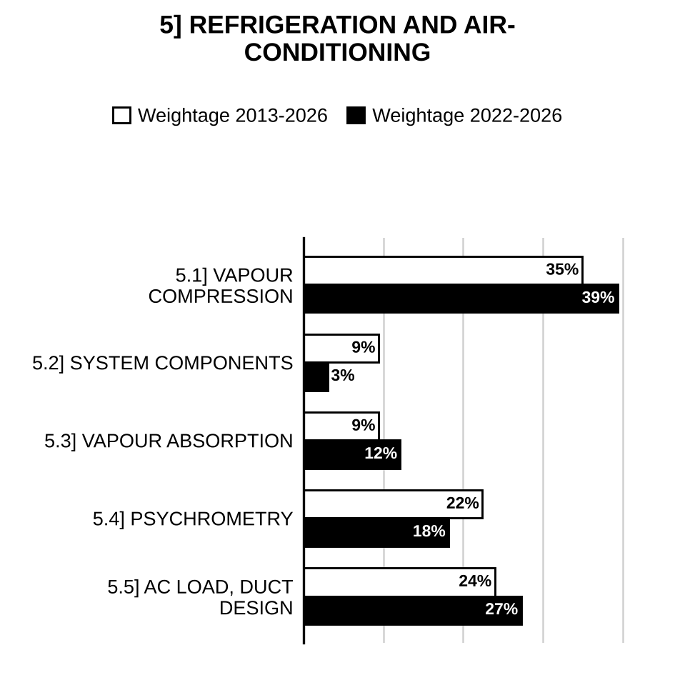
Here are all 127 Refrigeration and Air-Conditioning questions asked in UPSC Mechanical Engineering Optional Paper II from 1995 to 2026, arranged under the 5 topics of the official syllabus. Within each topic the latest questions come first.
Each question ends with a code such as [2024/15m/3b] – the year, the marks, the word limit (where UPSC set one) and the question number in the paper.
5.1] Vapour compression refrigeration
46 questions
List the deviations that occur in a compression process in actual vapour compression refrigeration cycle in comparison to simple saturated vapour compression refrigeration cycle. Also, specify the reasons for these deviations. [2026/10m/5d]
An R717 simple saturation cycle refrigerator operates at 40 °C condenser and −16 °C evaporator temperatures. Determine COP and power per TR. If a liquid-vapour regenerative heat exchanger is installed in the system, with the suction vapour at 15 °C, what will be the effect on COP and power per TR? Assume specific heat of vapour at condenser temperature as 3.1 kJ/kg-K, when no heat exchanger is used, and 2.9 kJ/kg-K, when heat exchanger is used. The properties of R717 are given in the table below:
| Temperature (°C) | Enthalpy (kJ/kg) Liquid () | Enthalpy (kJ/kg) Vapour () | Entropy (kJ/kg-K) Liquid () | Entropy (kJ/kg-K) Vapour () |
| −16 | 126.73 | 1442.60 | 0.72511 | 5.8420 |
| 40 | 390.59 | 1490.42 | 1.64377 | 5.1558 |
Draw the P-h diagram also. The specific heat of vapour corresponding to evaporator temperature may be assumed as 2.38 kJ/kg-K. [2026/20m/7b]
What is the chemical name of R134a? Is R134a an ecofriendly refrigerant? Clarify. [2025/10m/5e]
The following data refers to a single-stage vapour compression refrigeration system: Refrigerant = R134a Condenser temperature = 35 °C Evaporator temperature = – 10 °C Compressor motor speed = 2800 r.p.m. Clearance ratio = 0.03 Swept volume = Expansion index = 1.12 Compression isentropic efficiency = 75% Condensate subcooling in condenser = 5 °C Draw P-h diagram and determine the following: (i) The capacity of the plant in TR (ii) The power required in kW (iii) The COP (iv) The heat rejection to condenser (v) The second law efficiency The properties of R134a are given in the table:
| T (°C) | P (bar) | Specific volume of saturated vapour () | Enthalpy (kJ/kg) | Enthalpy (kJ/kg) | Entropy (kJ/kg-K) | Entropy (kJ/kg-K) |
| – 10 | 2.014 | 0.0994 | 186.7 | 392.4 | 0.9512 | 1.733 |
| 35 | 8.870 | – | 249.1 | 417.6 | 1.1680 | 1.715 |
Assume specific heat of liquid and vapour at 8.87 bar as 1.458 kJ/kg-K and 1.1 kJ/kg-K, respectively. The refrigerant at entry to compressor is in dry saturated state. [2025/20m/8a]
A refrigerator in a laboratory uses R-134a as the working substance. The high pressure is 1200 kPa, the low pressure is 101.3 kPa and the compressor is reversible. It should remove 500 W from a specimen currently at – 20°C (not equal to in the cycle), that is inside the refrigerated space. Find the cycle COP and the electrical power required. The enthalpy of superheated R-134a at 1200 kPa may be taken as 430 kJ/kg at compressor outlet. Use the R-134a property table attached. The refrigerant enters the compressor as saturated vapour. [2024/10m/5c]
A heat pump that operates on ideal vapour compression cycle with R-134a is used to heat a house and maintain it at 20°C, using underground water at 10°C as the heat source. The house is losing heat at a rate of 75 MJ/h. The evaporator and condenser pressure are 320 kPa and 800 kPa respectively. Determine the power input to the heat pump and the electric power saved by the heat pump instead of using a resistance heater. The enthalpy of superheated R-134a at 800 kPa at compressor outlet may be taken as 420 kJ/kg. Use the R-134a property table attached at the end. The inlet to the compressor may be taken as saturated vapour. [2024/20m/6b]
A 1 TR refrigeration plant works on R134a simple saturated vapour compression refrigeration cycle. The evaporator and condenser temperatures are –10 °C and 44 °C respectively. Determine the (i) mass flow rate of the refrigerant, (ii) compressor power, (iii) volumetric cooling capacity and (iv) COP. Also, calculate the (v) increase in the specific compressor work due to superheat horn and (vi) throttling loss, in comparison to reversed Carnot cycle operating between the same temperature limits. Consider the entry to compressor as saturated vapour and saturated liquid refrigerant is leaving the condenser in the reversed Carnot cycle. The properties of R134a are given in the table:
| (°C) | (bar) | Density of saturated liquid () | Specific volume of saturated vapour () | Enthalpy (kJ/kg): Liquid | Enthalpy (kJ/kg): Vapour | Entropy (kJ/kg-K): Liquid | Entropy (kJ/kg-K): Vapour |
| –10 | 2.005 | 1326 | 0.09963 | 186.78 | 392.75 | 0.951 | 1.734 |
| 44 | 11.3 | 1129 | 0.01786 | 262.38 | 421.28 | 1.209 | 1.71 |
Take specific heat of vapour refrigerant as 1.26 kJ/kg-K. [2023/20m/7b]
Discuss the effect of the following parameters on the performance of a vapor compression refrigeration system with the help of p-h diagram: (i) Suction pressure (ii) Delivery pressure (iii) Subcooling of liquid (iv) Superheating of vapors. [2022/10m/5d]
A VCR cycle refrigerator driven by a 60 kW compressor has a COP of 6.0. The enthalpies of saturated liquid and saturated vapor refrigerant at condenser temperature of 35 °C are 114.95 kJ/kg and 283.89 kJ/kg, respectively. The saturated refrigerant vapor leaving evaporator has an enthalpy of 275.76 kJ/kg. Find the temperature of refrigerant at the exit of compressor. The of refrigerant is 0.62 kJ/kg-K. [2022/20m/8a]
An ammonia vapour compression refrigeration system works between temperature limits of –6.7°C and 26.7°C. The vapour is dry at the end of compression and there is no under cooling of the liquid which is further throttled to the lower temperature. Find the COP of the machine. Use the above properties of ammonia.
| Temperature °C | Enthalpy (kJ/kg) | Enthalpy (kJ/kg) | Enthalpy (kJ/kg) | Entropy kJ/kg K | Entropy kJ/kg K |
| –6.7 | –29.3 | 1293.8 | 1264.5 | –0.113 | 4.752 |
| 26.7 | 125.6 | 1172.4 | 1297.9 | 0.427 | 4.334 |
[2021/20m/8a]
A food storage chamber requires a refrigeration system of 12 TR capacity with an evaporator saturation temperature of –8 °C and condenser temperature of 30 °C. The refrigerant R-12 is sub-cooled by 5 °C before entering the throttle valve, and the vapour is superheated inside the evaporator by 6 °C before entering the compressor. If the liquid and vapour specific heats are 1.235 kJ/kg-K and 0.733 kJ/kg-K respectively, find the (i) refrigerating effect per kg, (ii) mass of refrigerant circulated per minute and (iii) COP. The relevant properties of the refrigerant R-12 are given below:
| Saturation temperature (°C) | Enthalpy (kJ/kg) Liquid | Enthalpy (kJ/kg) Vapour | Entropy (kJ/kg-K) Liquid | Entropy (kJ/kg-K) Vapour |
| –8 | 28.70 | 184.06 | 0.1148 | 0.7007 |
| 30 | 64.59 | 199.62 | 0.2400 | 0.6853 |
[2020/20m/6b]
What are the environmental and safety properties of an ideal refrigerant? [2020/10m/8c]
A simple vapour compression refrigeration cycle using Freon 22 is designed for a load of 100 TR. The saturation temperatures in the evaporator and condenser are 5 °C and 40 °C respectively. The refrigerant leaves the evaporator and enters the compressor as saturated vapour. The refrigerant leaves the condenser and enters the expansion device as subcooled liquid with a subcooling of 5 °C. The specific heat of the vapour is 0.65 kJ/kg-K and the specific heat of the liquid is 1.1 kJ/kg-K for the refrigerant. Calculate (i) the mass flow rate (kg/s) of the refrigerant, (ii) the COP and isentropic compressor power and (iii) the heat rejected in the condenser. Use the following data:
| (°C) | (bar) | (kJ/kg) | (kJ/kg) | (kJ/kg-K) | (kJ/kg-K) | (m/kg) |
| 5 | 5.836 | 205.9 | 407.1 | 1.02115 | 1.7447 | 0.0404 |
| 40 | 15.331 | 249.53 | 416.4 | 1.16659 | 1.69953 | — |
[2019/20m/8a]
A Freon-12 refrigerator producing a cooling effect of 20 kJ/s operates on a simple cycle with pressure limits of 1.509 bar and 9.607 bar. The vapour leaves the evaporator dry saturated and there is no undercooling. Determine the power required by the machine. If the compressor operates at 300 r.p.m. and has a clearance volume of 3% of stroke volume, determine the piston displacement of the compressor. For compressor, assume that the expansion is following the law . Specific heat of vapour at condenser pressure is 0.747 kJ/kg-K:
Table: Properties of Refrigerant R-12
| Pressure (bar) | t (°C) | (m³/kg) | Enthalpy (kJ/kg) | Enthalpy (kJ/kg) | Entropy (kJ/kg-K), |
| 1.509 | −20 | 0.1088 | 54.23 | 178.61 | 0.7082 |
| 9.607 | 40 | — | 74.53 | 203.05 | 0.682 |
[2018/20m/8a]
Show processes of saturated vapour compression refrigeration cycle on p-v, t-s and p-h diagram and mark graphically on t-s diagram refrigerating effect, heat rejection by condenser and compressor work. [2017/10m/1b]
Explain harmful effects of R-12 and R-22 refrigerant. Write their chemical formula and NBP temperature. Also suggest new ecofriendly substitutes of these two with chemical composition. [2017/10m/5b]
A single stage, single acting vapour compression refrigeration system uses R-134a. Condenser and evaporator temperatures are 35°C and −10°C and refrigerant is undercooled by 5°C. Clearance volume per swept volume is 0.03 and swept volume is 269.4 cm³. Compressor speed and efficiency are 2800 rpm and 80% respectively. Expansion index is 1.12. Determine (i) Compressor exit temperature (ii) Enthalpy of refrigerant at compressor exit (iii) Enthalpy at the exit of the subcooler (iv) Volumetric efficiency of compressor (v) Refrigerant mass flow rate. Specific heat of vapour and liquid at condenser pressure are 1.1 kJ/kg-K and 1.458 kJ/kg-K respectively. Assume suction vapour dry saturated and isentropic compression.
Table: Properties of Refrigerant R-134a
| Pressure (bar) | t°C | , (m³/kg) | Enthalpy (kJ/kg) | Enthalpy (kJ/kg) | Entropy (kJ/kg-K) | Entropy (kJ/kg-K) |
| 2.104 | −10 | 0.0994 | 186.7 | 392.4 | 0.9512 | 1.733 |
| 8.870 | 35 | – | 249.1 | 417.6 | 1.1680 | 1.715 |
[2017/20m/6a]
Discuss any four thermodynamic desirable properties of an ideal refrigerant. [2016/10m/5d]
A vapour compression refrigeration cycle works between pressure limits 10 bar and 3 bar. The working fluid is dry at the end of compression and there is no undercooling before the expansion valve. If refrigerant flow rate is 10 kg/min, determine– (i) the COP; (ii) the capacity of the refrigerator. Table for properties of the refrigerant is as under:
| Pressure (bar) | Saturation temperature (°C) | Liquid heat (kJ/kg) | Latent heat (kJ/kg) | Liquid entropy (kJ/kg K) | Vapour entropy (kJ/kg K) |
| 10 | 25 | 298.9 | 1166.94 | 1.1242 | 5.0391 |
| 3 | –10 | 135.37 | 1297.68 | 0.5443 | 5.4770 |
[2016/20m/7b]
A refrigerating machine, rated to produce 40 tons of refrigeration, is used for air conditioning between the operative temperatures of 42° and 6°C of condenser and evaporator respectively. The refrigerant is dry saturated at the end of compressor. Find the capacity of the plant, power and capacities of compressor and condenser. Properties of refrigerant.
| Temp. (°C) | Pressure bar | Enthalpy (kJ/kg) | Enthalpy (kJ/kg) | Entropy (kJ/kg-K) | Entropy (kJ/kg-K) | Volume () |
| 42 | 1.957 | 249.7 | 410.7 | 1.125 | 1.6712 | 0.6975 |
| 6 | 0.5160 | – | 407.15 | 1.018 | 1.687 | 0.04035 |
| –32 | 0.0875 | – | 390.85 | 0.9178 | 1.715 | 0.1665 |
If the evaporator’s temperature is reduced to –32°C, what will be effect on capacity of plant, power and capacities of compressor and condenser? [2015/20m/7a]
An simple saturation cycle operates at temperatures of 35 °C and −15 °C. Determine the COP and HP per ton of refrigeration of the system:
| t (°C) | (kJ/kg) | (kJ/kg) | (kJ/kg K) | Superheated 20 K: h (kJ/kg) | Superheated 20 K: s (kJ/kg K) | Superheated 40 K: h (kJ/kg) | Superheated 40 K: s (kJ/kg K) |
| 35 | 69.5 | 201.5 | 0.6839 | 216.4 | 0.731 | 231.0 | 0.7741 |
| −15 | 181.0 | 0.7052 | 193.2 | 0.751 | 205.7 | 0.7942 |
[2014/10m/8a(i)]
In a standard vapour compression refrigeration cycle, the specific enthalpies of refrigerant at the end states of different processes in ascending order are 74.6 kJ/kg, 185.4 kJ/kg and 208.0 kJ/kg. If the mass flow rate of refrigerant is 30 kg/min, calculate power consumption and COP of the cycle. [2013/10m/1e]
An air refrigerator used for food storage provides 50 tons of refrigeration. The temperature of air entering the compressor is 7 °C and the temperature of air before entering into the expander is 27 °C. Assuming 30% more power is required than theoretical, find (i) actual COP of the cycle and (ii) kW capacity required to run the compressor. The quantity of air circulated in the system is 100 kg/min. The compression and expansion follow the law . Take and for air. [2013/25m/8b]
A commercial refrigerator with refrigerant 134a as the working fluid keeps a space cooled at – 30°C. It rejects heat to cooling water that enters the condenser at 18°C and at the rate of 0.25 kg/s and it leaves at 26°C. The refrigerant enters the condenser at 1.2 MPa and 65°C and it leaves at 42°C. The inlet state of compressor is 60 kPa and – 34°C. It gains a net heat of 450 W from the surroundings. Sketch T – S diagram and determine, (i) refrigeration load (ii) COP (iii) theoretical maximum refrigerant load for the same power input to the compressor. Given properties: [2012/20m/7c]
A saturated vapour compression refrigeration system is extracting heat from a thermal reservoir at −10 °C and rejecting heat to another thermal reservoir at 36 °C. The saturation temperature of evaporator is −20 °C and that of condenser is 46 °C. The mass flow rate of refrigerant (R–134 a) is 0.1 kg/s. Assume environment temperature equal to 36 °C. Find: (i) Refrigerating capacity in Tons (ii) Power input in kW (iii) COP (iv) COP of Carnot refrigeration cycle (v) Second law efficiency of the cycle. Compare with the help of T-s diagram, the vapour compression cycle and Carnot refrigeration cycle and show the deviation between the two cycles by shaded areas. Properties of refrigerant (Saturated)
| Temp (°C) | Saturation Pressure (MPa) | Enthalpy (kJ/kg) Sat liquid | Enthalpy (kJ/kg) Sat vapour | Entropy (kJ/kg-K) Sat liquid | Entropy (kJ/kg-K) Sat vapour |
| −20 | 0.13273 | 173.64 | 386.55 | 0.9002 | 1.7413 |
| −10 | 0.20060 | 186.70 | 392.66 | 0.9506 | 1.7334 |
| 36 | 0.91185 | 250.48 | 417.65 | 1.1717 | 1.7124 |
| 46 | 1.1903 | 265.47 | 421.92 | 1.2186 | 1.7089 |
Super heated
| Pressure (MPa) | (kJ/kg) | (kJ/kg-K) |
| 1 | 428.91 | 1.7413 |
| 1.2 | 436.12 | 1.7413 |
[2010/20m/6b]
A customer complained of poor cooling for an air-conditioning system of 100 TR capacity. The supplier carried out test on condenser which is water cooled and noted power input to the motor. The observations made are as under: Cooling water flow rate: 10 liter/sec; Inlet water temperature: 30°C; Outlet water temperature: 41.12°C; Power input to motor: 120 kW (94.92 % efficiency). Determine the actual refrigerating capacity and state whether the cooling capacity is lower, higher or as per specifications. [2008/20m/5d]
Discuss the importance of liquid-vapour heat exchanger (LVHE) in the vapour compression refrigeration system. Clearly mention advantages and disadvantages of using such heat exchangers. Represent the cycle on T-s and P-h diagrams and illustrate the influence of LVHE. [2008/15m/7b]
A refrigeration system operates using simple saturated cycle with a certain refrigerant. The condensing and evaporating temperatures for the refrigerant are 35°C and −15°C respectively. Determine the COP of the system. If a liquid vapour heat exchanger is installed in the system, with the temperature of the vapour leaving the heat exchanger at 15°C, what will be the change in the COP? Use the following data for the refrigerant used:
| t (°C) | (kJ/kg) | (kJ/kg) | (kJ/kg-K) | Superheated 20 K: h (kJ/kg) | Superheated 20 K: s (kJ/kg-K) | Superheated 40 K: h (kJ/kg) | Superheated 40 K: s (kJ/kg-K) |
| 35 | 69.5 | 201.5 | 0.6839 | 216.4 | 0.731 | 231.0 | 0.7741 |
| −15 | – | 181.0 | 0.7052 | 193.2 | 0.751 | 205.7 | 0.7942 |
[2007/30m/3a]
An ammonia ice plant operates on simple saturation cycle at the following temperatures: Condensing temperature = 40°C; Evaporation temperature = −15°C. It produces 10 tonnes of ice per day at −5°C from water at 30 °C. If the COP of the system is 5, determine: (i) Capacity of the refrigeration plant in tonnes of refrigeration (ii) Mass flow rate of the refrigerant, kg/min (iii) Isentropic discharge enthalpy, kJ/kg. Take: = 4.187 kJ/kg-K for water = 2.000 kJ/kg-K for ice; Latent heat of fusion of ice = 335 kJ/kg; Sensible enthalpy at 40°C = 600 kJ/kg; Enthalpy of sat. vapour at −15°C = 1675 kJ/kg. [2006/20m/5b]
A VCC refrigerating machine using R-12 refrigerant produces 10 tonnes of refrigeration at 10 °C when the ambient is at 35°C. A temperature difference of minimum 5°C is required at the evaporator and condenser for spontaneous heat transfer. The refrigerant is dry saturated at the outlet and to the inlet of compressor. The adiabatic efficiency of the compressor is 90%. The enthalpy at the end of isentropic compression is estimated to be 370 kJ/kg. Determine: (i) COP (ii) Power of the compressor (iii) Capacity of the condenser. Represent the cycle on hand drawn T-S plane and show the refrigerating effect, compressor work and condenser capacity on the same. Properties of R-12 are:
| Temperature (°C) | Pressure (bar) | Specific Enthalpy, kJ/kg: Sensible | Specific Enthalpy, kJ/kg: Evaporation |
| 5 | 3.62 | 204.64 | 148.97 |
| 10 | 4.23 | 209.32 | 146.37 |
| 15 | 4.91 | 214.10 | 143.69 |
| 30 | 7.45 | 228.54 | 135.04 |
| 35 | 8.47 | 233.50 | 131.90 |
| 40 | 9.60 | 238.53 | 128.62 |
[2006/30m/6a]
Show that the COP of a cascade refrigeration system is where , and and COP’s of low temperature and high temperature side respectively. [2005/20m/5b]
A vapour compression refrigerator operates between the pressure limits of 462.47 and 1785.90 . At entry to the compressor the refrigerant is dry saturated and after compression it has a temperature of 59°C. The compressor has a bore and stroke of 75 mm and runs at 8 rev/s with a volumetric efficiency of 80 percent. The temperature of the liquid refrigerant as it leaves the condenser is 32°C and the specific heat capacity of the superheated vapour may be assumed constant. Determine: (i) The coefficient of performance of the refrigerator (ii) The mass flow of the refrigerant in kg/h. (iii) The cooling water required by the condenser in kg/h if the cooling water temperature rise is limited to 12°C. Take the specific heat capacity of water as 4.187 kJ/kg K and the specific heat of liquid refrigerant as 1.32 kJ/kg K. The relevance properties of the refrigerant are given in the table below:
| Pressure | Sat. temp. °C | Sp. enthalpy | Sp. enthalpy | Sp. vol. () | Sp. vol. () | Sp. entropy | Sp. entropy |
| 462.47 | –10 | 35.732 | 231.40 | 0.0008079 | 0.04573 | 0.1418 | 0.8614 |
| 1785.90 | 40 | 99.270 | 246.40 | 0.0009487 | 0.01105 | 0.3537 | 0.8093 |
[2004/40m/7a]
In a refrigeration system of 10 TR cooling capacity using , the evaporator and condenser temperatures are -10°C and 45°C respectively. Properties of at saturation are.
| Temperature °C | Sp. volume | Enthalpy kJ/kg | Enthalpy kJ/kg | Entropy kJ/kg-K | Entropy kJ/kg-K |
| –10 | 0.0654 | 34.25 | 247.37 | 0.1374 | 0.9473 |
| 45 | 0.0133 | 101.76 | 261.95 | 0.3662 | 0.8697 |
Consider standard vapour compression cycle with inlet to compressor as saturated vapour and inlet to expansion valve as saturated liquid. Assume that vapour may be treated as perfect gas in desuperheating process with average specific heat of 0.9335 kJ/kg-K. Show the cycle on T-s and p-h diagrams. Find (i) compressor outlet temperature and enthalpy, (ii) mass flow rate of refrigerant, (iii) work requirement, (iv) condenser heat rejection (v) COP and (vi) swept volume of compressor in assuming 100% volumetric efficiency. [2003/30m/7a]
A vapour compression refrigerator works between pressure limits of 10 bar and 3 bar. The working fluid is dry at the end of compression and there is no undercooling before the expansion valve. If refrigerant flow rate is 10 kg/min, determine (i) COP and (ii) the capacity of the refrigerant. Table for properties of the refrigerant is as under.
| Pressure bar | Saturation temperature °C | Liquid heat kJ/kg | Latent heat kJ/kg | Liquid entropy kJ/kg K |
| 10 | 25 | 298.90 | 1166.94 | 1.1242 |
| 3 | -10 | 135.37 | 1297.68 | 0.5443 |
[2002/30m/7a]
Calculate the (i) cop. (ii) power requirement and (iii) cooling capacity of a compressor working between 22.68 bar and 64.32 bar pressures. The liquid in the condenser gets cooled, by another system, to 15°C before entering the expansion valve. The system is assumed to work on wet-compression with x = 0.9. The compressor data stroke volume = 500 c.c.; r.p.m. = 500 and . Property values are: sp. heat of vapour = 2.4 kJ/kg°C and.
| p (bar) | enthalpy (kJ/kg) liq. | enthalpy (kJ/kg) vap. | v () liq. | v () vap. | S (kJ/kg°C) liq. | S (kJ/kg°C) vap. | t (°C) |
| 22.68 | 49.62 | 322.86 | 0.00101 | 0.0166 | 0.1976 | 1.2567 | -15 |
| 50.92 | 127.75 | 308.08 | 0.00130 | 0.0066 | 0.4697 | 1.0959 | 15 |
| 64.32 | 164.17 | 283.63 | 0.00147 | 0.0042 | 0.5903 | 0.9912 | 25 |
[2001/30m/6a]
What are the harmful environmental effects of conventional refrigerants? Name any one eco-friendly refrigerant which is being commercially used and discuss its important characteristics. [2000/20m/200w/5b]
A refrigerating plant of 10 kW capacities operates in the quasideal vapour compression cycle. The refrigerant is R 134 a. The saturation temperatures in the evaporator and condenser are respectively -20°C and 40°C. The plant includes a heat exchanger in which the saturated liquid leaving the condenser is subcooled to 30°C by the saturated vapour leaving the evaporator. The subcooled liquid is then throttled to -20 °C before entering the evaporator and the vapour leaving the heat exchanger is compressed isentropically to the condenser pressure. Sketch the schematic diagram and the cycle on p-h and T-s diagrams, numbering the important point. Calculate the mass flow rate of the refrigerant and power to be supplied to the compressor. The mechanical efficiency of the compressor may be assumed 80%. The compressor used by the plant is a single-stage single-acting reciprocating compressor having stroke-diameter ratio of 1.2 and a speed of 240 rev/min. Assuming compressor volumetric efficiency to be 80% determine the diameter and stroke of the compressor. Properties of refrigerant may be obtained from table below:
| t (°C) | (bar) | () | Enthalpy kJ/kg Liquid | Enthalpy kJ/kg Vapour | Entropy kJ/kg-K Liquid | Entropy kJ/kg-K Vapour | Specific heat kJ/kg-K Liquid | Specific heat kJ/kg-K Vapour |
| -20 | 1.3268 | 0.1474 | 173.82 | 386.66 | 0.9009 | 1.7417 | 1.282 | 0.805 |
| 40 | 10.165 | 0.0199 | 256.35 | 419.58 | 1.1905 [?] | 1.7115 | 1.5 | 1.12 |
[2000/35m/6b]
What are the essential properties of a good refrigerant? What refrigerants are used and what factors are considered in selecting a refrigerant for (i) Ice production factory and (ii) Domestic refrigerators? What are the recent trends in refrigerants to avoid ozone depletion in the stratosphere? [1999/20m/200w/5a]
An ammonia vapour compression refrigeration plant has two stages of compression and one evaporator. After leaving the condenser at 11.666 bar as saturated liquid without under-cooling it passes the first throttle valve from which it emerges at 4.975 bar to enter a flash chamber. The liquid from flash chamber is then throttled to 2.909 bar and passes to the evaporator while the dry saturated vapour is passed to a receiver connecting the L.P and H.P cylinders. Determine (i) the amount of vapour bled off at the flash chamber. (ii) the coefficient of performance. Properties of ammonia:
| Pressure bar | Temperature °C | Enthalpy kJ/kg: | Enthalpy kJ/kg: | Entropy kJ/kg K: | Entropy kJ/kg K: | kJ/kg K |
| 11.665 | 30 | 332.9 | 1467.9 | 1.2028 | 4.9805 | 2.958 |
| 4.975 | 4 | 199.6 | 1447.6 | 0.7815 | 5.2852 | 2.958 |
| 2.909 | – 10 | 135.2 | 1432.0 | 0.5440 | 5.4730 | 2.958 |
[1999/40m/7b]
A refrigerator with evaporator and condenser temperatures of −10 °C and 32 °C uses R11. The vapour is superheated by 8 °C at entry to the compressor and the superheating is obtained by undercooling the liquid before entry to evaporator. Assuming isentropic compression, determine the power required for a cooling load of 350 kJ/s, the overall efficiency for power use being 75%. Discuss about the choice of the type of compressor for this plant. Properties values are tabulated below.
| Temp. °C | Specific Volume of vapour | Enthalpy kJ/kg: liquid | Enthalpy kJ/kg: vapour | Entropy of vapour kJ/kg K | Specific heat of kJ/kg K |
| – 10 | 0.61141 | 191.44 | 384.64 | 1.7023 | 0.562 |
| 32 | 0.13104 | 227.96 | 406.23 | 1.6807 | 0.620 |
[1998/40m/7b]
State the factors considered in selection of a refrigerant and compare the two commonly used refrigerants viz, ammonia and freon. [1997/20m/200w/5d]
An ammonia ice plant operates between a condenser temperature of 35°C and evaporator temperature of -15°C. It produces 10 tons of ice per day from water at 30°C to ice at -5°C. Assuming simple saturation cycle, determine (i) the capacity of the refrigerating plant (ii) the mass flow rate of refrigerant (iii) the discharge temperature (iv) the compressor cylinder diameter and stroke (v) the power of compressor motor and (vi) the theoretical and actual COP. Take volumetric efficiency of compressor = 0.65; speed of compressor = 1200 rpm; Stroke/ Bore ratio of compressor = 1.2; adiabatic efficiency of compressor = 0.85; mechanical efficiency of compressor = 0.95. Use the properties of Ammonia as given below:
| Saturation temp. t (°C) | Saturation pressure p (bar) | Saturated liquid & vapour (m/kg) | (m/kg) | (kJ/kg) | (kJ/kg) | (kJ/kgK) | (kJ/kgK) | Vapour superheated 50° C: h (kJ/kgK) | 50° C: s (kJ/kgK) | 100° C: h (kJ/kgK) | 100° C: s (kJ/kgK) |
| -15 | 2.36 | 1.52 | 0.509 | 112.3 | 1426 | 0.457 | 5.549 | 1543 | 5.963 | 1656 | 6.3 |
| 35 | 13.5 | 1.7 | 0.096 | 3417.5 [?] | 1476 | 1.282 | 4.93 | 1616 | 5.368 | 1744 | 5.7 |
[1997/60m/6]
Explain why freon refrigerants are being phased out. Name any proposed substitute refrigerant and give its relevant properties as compared to freon-12. [1996/20m/6a]
A 15 ton Freon refrigeration plant has twin cylinder single acting compressor having bore 1.5 times stroke and operating at 960 rpm. The temperature of the refrigerant sub-cooled as liquid in the condenser is 248 K while the temperature of the refrigerant superheated as gas in the evaporator is 268 K. The condenser temperature is 303 K. Using the refrigerant properties tabulated below, determine. (i) Mass of refrigerant circulated per minute (ii) Theoretical kilo-watt power required to operate the plant (iii) the theoretical COP of the plant (iv) Heat removed in the condenser (v) The compressor bore and stroke. Assume average liquid specific heat as 0.963 kJ/kg K and average vapour specific heat as 0.615 kJ/kg K.
| Saturation Temp. t, K | Absolute pressure P (bar) | Specific volume () | Enthalpy of liquid (kJ/kg) | Enthalpy of vapour (kJ/kg) | Entropy of liquid (kJ/kgK) | Entropy of vapour (kJ/kg K) |
| 263 | 2.19 | 0.0767 | 26.9 | 183.2 | 0.1080 | 0.7020 |
| 303 | 7.45 | 0.0235 | 64.6 | 199.6 | 0.2399 | 0.6854 |
[1996/40m/6b]
With reference to the refrigeration and air-conditioning practice explain why.
(i) ammonia which is a very good refrigerant, is not used in domestic vapour compression refrigerators. [1995/10m/200w/5b(i)]
(ii) Hydrocarbons such as propane and butane are being tried as substitutes for freon refrigerants. [1995/10m/200w/5b(ii)]
A vapour compression ice plant has a twin-cylinder single-acting compressor with a bore and stroke of 90 cm and 70 cm respectively. It works between pressure limits 10.587 bar and 1.826 bar and has mean effective pressure of 334 kN per sq meter. It runs at 500 rev/min, temperature of refrigerant at entry and exit from condenser 65°C and 32°C respectively; rate of flow of cooling water 13 kg per minute with a rise of 8°C and produces at 27°C, 360 kg of ice in 8 hours from water; latent heat of ice is 335 kJ. Find (a) the theoretical coefficient of performance (b) the actual coefficient of performance and (c) the mass flow of refrigerant per minute. Draw up an energy balance of the plant. The relevant properties of the refrigerant used are:
| Pressure bar | Sat temp. C | Enthalpy kJ/kg K Liquid | Enthalpy kJ/kg K Vapour | Entropy kJ/kg K |
| 10.587 | 44 | 78.679 | 204.544 | 0.6814 |
| 1.826 | -15 | 22.23 | 180.973 | 0.7051 |
The average specific heat of liquid refrigerant is 1.256 and for superheated vapour it is 0.645 kJ/kg K. [1995/40m/6b]
5.2] Refrigeration system components
13 questions
The following data refers to a single-stage vapour compression refrigeration system: Refrigerant = R134a Condenser temperature = 35 °C Evaporator temperature = – 10 °C Compressor motor speed = 2800 r.p.m. Clearance ratio = 0.03 Swept volume = Expansion index = 1.12 Compression isentropic efficiency = 75% Condensate subcooling in condenser = 5 °C Draw P-h diagram and determine the following: (i) The capacity of the plant in TR (ii) The power required in kW (iii) The COP (iv) The heat rejection to condenser (v) The second law efficiency The properties of R134a are given in the table:
| T (°C) | P (bar) | Specific volume of saturated vapour () | Enthalpy (kJ/kg) | Enthalpy (kJ/kg) | Entropy (kJ/kg-K) | Entropy (kJ/kg-K) |
| – 10 | 2.014 | 0.0994 | 186.7 | 392.4 | 0.9512 | 1.733 |
| 35 | 8.870 | – | 249.1 | 417.6 | 1.1680 | 1.715 |
Assume specific heat of liquid and vapour at 8.87 bar as 1.458 kJ/kg-K and 1.1 kJ/kg-K, respectively. The refrigerant at entry to compressor is in dry saturated state. [2025/20m/8a]
Explain the concept of balance point between the compressor and the capillary tube in refrigeration systems. [2021/10m/5d]
Explain in brief as to why capillary tube is preferred to other throttling devices in household refrigerator. [2020/10m/5e]
Explain how a simple capillary tube works as an expansion device in vapour compression refrigeration system. What are the advantages and disadvantages of capillary tube as an expansion device? [2019/10m/6c]
Explain briefly the different types of compressors used in refrigeration. [2018/10m/5c]
A Freon-12 refrigerator producing a cooling effect of 20 kJ/s operates on a simple cycle with pressure limits of 1.509 bar and 9.607 bar. The vapour leaves the evaporator dry saturated and there is no undercooling. Determine the power required by the machine. If the compressor operates at 300 r.p.m. and has a clearance volume of 3% of stroke volume, determine the piston displacement of the compressor. For compressor, assume that the expansion is following the law . Specific heat of vapour at condenser pressure is 0.747 kJ/kg-K:
Table: Properties of Refrigerant R-12
| Pressure (bar) | t (°C) | (m³/kg) | Enthalpy (kJ/kg) | Enthalpy (kJ/kg) | Entropy (kJ/kg-K), |
| 1.509 | −20 | 0.1088 | 54.23 | 178.61 | 0.7082 |
| 9.607 | 40 | — | 74.53 | 203.05 | 0.682 |
[2018/20m/8a]
A single stage, single acting vapour compression refrigeration system uses R-134a. Condenser and evaporator temperatures are 35°C and −10°C and refrigerant is undercooled by 5°C. Clearance volume per swept volume is 0.03 and swept volume is 269.4 cm³. Compressor speed and efficiency are 2800 rpm and 80% respectively. Expansion index is 1.12. Determine (i) Compressor exit temperature (ii) Enthalpy of refrigerant at compressor exit (iii) Enthalpy at the exit of the subcooler (iv) Volumetric efficiency of compressor (v) Refrigerant mass flow rate. Specific heat of vapour and liquid at condenser pressure are 1.1 kJ/kg-K and 1.458 kJ/kg-K respectively. Assume suction vapour dry saturated and isentropic compression.
Table: Properties of Refrigerant R-134a
| Pressure (bar) | t°C | , (m³/kg) | Enthalpy (kJ/kg) | Enthalpy (kJ/kg) | Entropy (kJ/kg-K) | Entropy (kJ/kg-K) |
| 2.104 | −10 | 0.0994 | 186.7 | 392.4 | 0.9512 | 1.733 |
| 8.870 | 35 | – | 249.1 | 417.6 | 1.1680 | 1.715 |
[2017/20m/6a]
Justify the suitability of thermostatic expansion valve in comparison to automatic expansion valve. [2015/10m/5a]
What are the functions of condenser in a refrigerating machine? Name different types of condensers. Describe with neat sketch the evaporative condenser. [2015/10m/6c]
A thermostatic expansion valve using R- in the power assembly is designed to produce 10°C superheat at an evaporator temperature of 0°C. What will be the superheat that it will maintain when the evaporator temperature is –30°C? Given for R-, the saturation pressure temperature data:
| Temp (°C) | –30 | –25 | –20 | –15 | –10 |
| Pressure (bar) | .8438 | 1.065 | 1.327 | 1.64 | 2.006 |
| Temp (°C) | –5 | 0 | 5 | 10 | |
| Pressure (bar) | 2.43 | 2.928 | 3.5 | 4.146 |
[2011/15m/5a]
Why do some thermostatic expansion valves have an ‘external equalizer’? How does it improve its performance? [2011/20m/6c]
Comment on the following (Be brief) with the help of schematic diagram, if required (i) In the reciprocating compressors used in vapour compression system, the mass of refrigerant discharged by the compressor reduces as the pressure ratio is increased. (ii) Thermostatic expansion valve is preferred over automatic expansion valve as throttling device. (iii) COP of refrigeration system increases when water cooled condenser is used in place of air cooled condenser. (iv) Vapour at suction to the hermetically sealed compressor is always superheated vapour. (v) For low sensible heat factor applications, re-heat is necessary. [2010/20m/5d]
Explain how would you find whether a refrigerator is undercharged or overcharged. How would you detect leaking of refrigerant from a refrigerator? Name and describe any equipment/instrument available for this purpose. [1995/20m/6a]

Preparing for Prelims too?
Our UPSC Prelims Topic-wise PYQ eBook covers every Prelims question with detailed explanations, so you can see exactly where UPSC asks from.
View the BookDownload Free Sample5.3] Vapour absorption refrigeration
13 questions
“The COP of a simple vapour absorption refrigeration system is lower than the COP of a simple vapour compression refrigeration system under identical temperature conditions.” Is this statement correct thermodynamically? Justify your answer. [2026/10m/6c]
Why is vapour absorption refrigeration system considered to be a better option in comparison to vapour compression refrigeration system for large capacity refrigeration and air-conditioning plants? [2025/10m/6c]
Compare vapour compression and vapour absorption refrigeration systems. [2023/10m/5d]
Explain -water vapor absorption refrigeration system with a neat diagram. What are the desired properties of refrigerant-absorber combination? [2022/10m/6c]
The operating temperatures of a simple vapour absorption refrigeration system are–generator 100 °C; condenser and absorber 45 °C; evaporator 2 °C. The system has refrigeration capacity of 125 kW and heat input to the system is 180 kW. The solution pump work is negligible. (i) Find the COP of the system and total heat rejection rate from the system. (ii) An inventor claims that by improving the design of all the components of the above system, he could reduce the heat input to the system by 90 kW, while keeping the refrigeration capacity and operating temperature same as before. Examine the validity of the claim. [2020/10m/5b]
Enumerate the desirable properties of refrigerant-absorbent pairs for vapour absorption refrigeration system. [2019/5m/5c(i)]
What are the drawbacks of presence of water vapour in the evaporator and condenser of an aqua-ammonia absorption refrigeration system? [2019/5m/5c(ii)]
Explain the working of practical -water vapour absorption refrigeration system with a diagram. [2018/10m/8c]
Explain, with the help of neat sketches, vapour absorption cycle for refrigeration and also derive an expression to calculate ideal COP of it. [2016/20m/6c]
Draw a neat sketch of aqua-ammonia vapour absorption system. On this sketch: (i) Indicate thermodynamic state points with (1) at the inlet of pump. (ii) Show the direction of the following energy transfers to various components: – energy transfer to absorber; – energy transfer to pump; – energy transfer to generator; – energy transfer to dephlegmator; – energy transfer to condenser; – energy transfer to evaporator. (iii) Mention for each of the energy transfers in (ii) above whether it is in the form of work or heat. (iv) With heat sink temperature of 27 °C, heat source temperature of 127 °C and refrigeration temperature of −13 °C, find max COP of the vapour absorption system and mention the assumptions made. [2010/20m/7b]
How, in a refrigeration system using ammonia, the compressor could be replaced by another suitable set of equipments? [2001/20m/200w/5c]
Describe giving the layout, a refrigeration system that can use solar heat as the input. [1998/20m/200w/5b]
Compare vapour compression and vapour absorption systems for the following applications (i) Household use (ii) Ice plant (iii) Central air-conditioning (iv) Process cooling, and (v) Process air-conditioning. [1998/20m/7a]
5.4] Psychrometry and air-conditioning processes
30 questions
What is meant by effective temperature? List and explain briefly the factors which affect optimum effective temperature in air-conditioning. [2025/10m/7b(i)]
Explain psychrometric process of adiabatic mixing of two air streams. [2025/10m/7b(ii)]
Draw the schematic arrangement diagram of an air washer. Describe the various air-conditioning processes it can perform. [2024/10m/5e]
In a cooling tower used in a thermal power plant, 26,000 kg/s of air enters at DBT = 20°C and relative humidity at 20%. It leaves the cooling tower at 35°C DBT and 80% relative humidity. I. Find the following: (i) Total heat added to the air (ii) Evaporation loss of water (iii) WBT of the air at inlet and exit (iv) Change in the volume flow rate of the air in the cooling tower II. Explain the process on the Psychrometric chart. Use Psychrometric chart attached at the end. [2024/20m/7a]
Without using psychrometric chart, calculate (i) relative humidity, (ii) humidity ratio, (iii) dew point temperature and (iv) enthalpy of moist air, when DBT is 35 °C and WBT is 23 °C. The barometer reads 755 mm of Hg. Use modified Apjohn equation (take values of pressure in bar) where, = = partial pressure of water vapour (w.v.) corresponding to DPT = partial pressure of w.v. corresponding to WBT = DBT = WBT = barometric pressure Use the properties of water vapour given below:
| (°C) | Vapour pressure (bar) |
| 10 | 0.012272 |
| 12 | 0.014017 |
| 14 | 0.015977 |
| 16 | 0.018173 |
| 18 | 0.020630 |
| 20 | 0.023373 |
| 22 | 0.026431 |
| 24 | 0.029832 |
| 32 | 0.047552 |
| 34 | 0.053201 |
| 36 | 0.059423 |
[2023/10m/5e]
A moist air sample has dry bulb temperature of 30°C and specific humidity of 11.5 gm of water vapour per kg dry air. If the saturation vapour pressure of water at 30°C is 4.24 kPa and the total pressure is 90 kPa then what is the relative humidity of the air sample? [2021/10m/6c]
Atmospheric air at 1.033 bar and 35 °C DBT and 60% RH is undergoing a psychrometric process. During the process, the specific humidity of air is reduced by 5 gm/kg of dry air and the DBT of air is reduced to 25 °C, while the pressure is maintained constant. Determine the relative humidity and dew-point temperature of air in the final condition. Solve the problem using only psychrometric relations.
Saturated Water-Temperature Table
| Temperature T (°C) | Saturated Pressure (kPa) |
| 0.01 | 0.6117 |
| 5 | 0.8725 |
| 10 | 1.2281 |
| 15 | 1.7057 |
| 20 | 2.3392 |
| 25 | 3.1698 |
| 30 | 4.2469 |
| 35 | 5.6291 |
| 40 | 7.3851 |
| 45 | 9.5953 |
[2019/10m/5e]
What are human comfort and effective temperature? Sketch comfort zone on psychrometric chart. [2018/10m/5e]
In a laboratory test, a psychrometer recorded dry-bulb temperature as 35 °C and wet-bulb temperature as 28 °C. Calculate (i) vapour pressure, (ii) relative humidity, (iii) specific humidity, (iv) vapour density in air, (v) dew point temperature and (vi) enthalpy of mixture. Barometric pressure is 1.01325 bar. Do not use psychrometric chart. Saturation pressures of water vapour at 35 °C and 28 °C are 0.05628 bar and 0.03782 bar respectively. Saturation temperature at partial pressure of water vapour is 25.6 °C. [2018/20m/6b]
What is an adiabatic saturation process? Why does the enthalpy of an air-vapour mixture remain constant during this process? [2016/10m/5e]
Air at dry-bulb temperature of 30 °C and 60% relative humidity enters a cooling coil at the rate of . (i) Determine the refrigeration in ton needed to bring the temperature of the air to the coil temperature of 23 °C and also the relative humidity at that condition. (ii) If the effective surface temperature of the cooling coil or ADP is 12 °C and the by-pass factor is 0.1, determine the refrigeration in ton needed and the mass of water condensed out at the cooling coil per minute. Determine also the sensible heat factor for the process through the coil. [2016/20m/8a]
In a drier operating at steady state atmospheric air at 30°C and 101.325 kPa with a relative humidity of 40% is first heated to 110°C at constant pressure. The heated air is then allowed to pass over the material to be dried and the air leaves the drier at 70°C with a relative humidity of 0.5. If it is required to remove 60 kg/min of moisture from the material, determine the mass flow rate of dry air required in kg/min and the rate of heat transfer to the air as it passes through the heating unit. Use .
[Figure: Psychrometric chart (barometric pressure 1.01325 bar, sea level) printed below the question on the same page; marked “Do not write your Roll No. on this Sheet”] [2015/20m/6a]
Mechanical air-conditioning can be used in all geographical locations, whereas desert air-coolers can be used only in some geographical locations. Explain why. Show the processes involved in both these equipments. [2014/10m/5d]
Show that the enthalpy of humid air per kg of dry air is given by where = humid air specific heat = , w = specific humidity kg/kg of dry air, at 0 °C for water and DBT = dry-bulb temperature. [2014/10m/6c]
What is the significance of by-pass factor? For a heating coil, derive an expression of by-pass factor. Find the expression for efficiency also for heating coil. [2013/10m/5d]
of air per minute at 15 °C DBT and 80% relative humidity is sensibly heated until its temperature becomes 22 °C. Saturation pressures of water vapour at 15 °C and 22 °C are 0.017 bar and 0.02645 bar respectively. Find heat added to air per minute. Take atmospheric pressure = 1.013 bar. [2013/25m/8a]
An air-conditioning system (see figure) operates at a total pressure of 1 atm. It consists of a heating section and a humidifier that supplies wet steam (saturated) at 100°C. Air enters the heating section at 10°C and 70 percent relative humidity at the rate of 35 . It leaves at 20°C and 60% relative humidity. Determine (i) temperature and relative humidity of air when it leaves the heating section, (ii) the rate of heat transfer to the heating section, and (iii) the rate at which water is added to the air in the humidifying section.
[Figure: Duct with air at 1 atm flowing left to right; state ① at inlet: 10°C, 70%, 35 ; a heater (heating coil) in the duct, followed by state ②; then a humidifier – a vertical pipe supplying “Sat. steam 100°C, h = 2675 kJ/kg” and spraying it into the air (three arrows) – followed by state ③ at exit: 20°C, 60%]
Also draw skeleton Psychrometric chart represention showing the process. [2012/20m/3c]
Cold water bottles kept in a room often start condensing atmospheric moisture. What is the minimum temperature to which water bottle can be cooled without any dripping of moisture from its surface when kept in a room at 25°C DBT and 60% RH? If it is desired that a water bottle at 10°C should also not condense moisture on its surface, what should be the RH in the room, keeping the DBT the same? [2011/15m/5b]
In a winter heating air-conditioning system 1 kg/s of ambient air at 7°C DBT, 80% RH is sensibly heated, then adiabatically saturated to a high humidity of RH = 90%, and then further sensibly heated to the desired outlet state of 25°C DBT and 50% RH. Determine the temperature of air at various state points and show all the processes on a psychrometric chart. Also determine the amount of moisture added per hour in the adiabatic saturator. [2011/30m/7b]
Illustrate the following processes on psychrometric chart with initial state of moist air as dry bulb temperature equal to 20 °C and relative humidity of 50%: (i) Cooling and humidification (ii) Heating and humidification (iii) Humidification at constant dry bulb temperature. Mention one application each for above humidification processes. If the moist air leaves the system for the case (iii) above, at 90% relative humidity, determine per unit mass of dry air: (i) increase in humidity ratio, (ii) increase in enthalpy, (iii) increase in dry bulb temperature, (iv) Determine Sensible Heat Factor (SHF) for this process. [2010/20m/8c]
20 of air per minute at 30° C DBT and 60% RH is sensibly cooled to 22° C DBT. Take saturation pressure of water vapour at 30° C and 22° C temperatures to be 0.425 bar and 0.0265 bar respectively. Find heat removed from air. Take atmospheric air pressure bar. [2009/20m/8b]
Develop an expression for enthalpy of moist air per unit mass of dry air as under: kJ/kg where t is DBT and w is humidity ratio. [2008/15m/7a]
Moist air enters a chamber at 5°C DBT and 2.5°C WBT at a rate of . The barometric pressure is 1.01325 bar. While passing through the chamber, the air absorbs sensible heat at the rate of 40.7 kW and picks up 40 kg/hr of saturated steam at 110°C. Determine the dry and wet bulb temperatures of leaving air. Properties of steam are given below: Enthalpy of saturated steam at 110°C is 2691.3 kJ/kg. [2008/30m/7c]
10 cu m of atmospheric air at 25°C DBT and 12°C WBT is flowing per minute through a duct. Dry saturated steam at 100°C is injected through the duct. Dry saturated steam at 100°C is injected into the air stream with a rate of 1.2 kg/min. (i) What is the temperature of air after mixing the steam? (ii) What is the relative humidity of air after mixing the steam? [2007/30m/3b]
Explain the concept of effective temperature (ET) used in air-conditioning practice. Discuss the parameters on which it depends. [2006/20m/5c]
What is the role of a cooling tower in a power plant? What is meant by range and approach and what purpose does the fill serve in a cooling tower? [2003/20m/200w/5c]
Show the following processes on the psychrometric chart: (i) Heating and humidification (ii) Cooling and dehumidification (iii) Cooling and humidification (iv) Heating and dehumidification (v) Adiabatic saturation. [2002/20m/200w/5a]
Discuss and show on the skeleton psychrometric chart, the process for the air passing through air washers with three types of spray (i) recirculated (ii) chilled and (iii) heated water. [2001/20m/200w/5b]
With reference to air-conditioning practice, explain the difference between human comforts and industrial air-conditioning pointing out the various parameters in each of these applications. Give suitable examples. Sketch and discuss a comfort chart. [2000/20m/200w/5c]
A mixture of air and water vapour at 1.01325 bar. 16°C has dew point of 5°C. Calculate the relative humidity and specific humidity. [2000/20m/6a]
5.5] Air-conditioning load and duct design
25 questions
What is the difference between room ADP and coil ADP? Under which condition, both will have the same value? [2026/10m/5e]
An air-conditioned space is maintained at 25 °C DBT and 50% RH. The outside conditions are 40 °C DBT and 27 °C WBT. The space has a sensible heat gain of 24.5 kW. Conditioned air is supplied to the space as saturated air at 10 °C. The equipment consists of an air washer. The air entering the air washer comprises 25% of outside air, the remainder being recirculated room air. Calculate the– (i) volume flow rate of air supplied to space; (ii) room sensible heat factor; (iii) cooling load (in TR) of air washer. Psychrometric chart is given at the end. Also, draw the schematic diagram and show the various processes on a skeleton psychrometric chart.
[Attached: Psychrometric chart supplied at the end of the paper (page 16), headed “For Question No. 8(a)”: “Psychrometric Chart, Barometric Pressure 1.01325 bar, Sea Level” (printed rotated), with dry bulb temperature (°C), wet bulb or saturation temperature, specific enthalpy at saturation (kJ/kg air), relative humidity curves, specific volume lines ( dry air), enthalpy deviation lines (kJ/kg dry air), moisture content scale (kg/kg dry air) and a sensible heat factor scale.] [2026/20m/8a]
Explain briefly the various methods of air-conditioning duct design. [2023/10m/6c]
Air flowing at the rate of at 40 °C DBT and 50% RH is mixed with another stream of air flowing at the rate of at 26 °C DBT and 50% RH. The mixture flows over a cooling coil whose ADP temperature is 10 °C and bypass factor is 0.2. Find the DBT and RH of air leaving the coil. If this air is supplied to an air-conditioned room, where DBT of 26 °C and RH of 50% are maintained, then calculate the (i) room sensible heat factor and (ii) coil cooling capacity in tons of refrigeration. Draw a schematic diagram of the system and show all the processes on a skeleton psychrometric chart. Psychrometric chart is given. [2023/20m/8b]
The room air is recirculated at the rate of per minute and the outdoor air enters a cooling coil of an air conditioner at 32 °C DBT and 18 °C WBT. The effective surface temperature of the coil is 4.5 °C. The surface area of the coil is such as would give 12 kW of refrigeration with the given entering conditions of air. Determine the DBT and WBT of the air leaving the coil and the coil bypass factor. [Psychrometric chart is given at the end of this Paper]. [2022/10m/5e]
A food processing room has a very high latent heat load and is required to be air conditioned as per the following data: Room design conditions: 20 °C DBT, 60% RH Outside conditions: 45 °C DBT, 30 °C WBT Room sensible heat: 35 kW Room latent heat: 20 kW The ventilation air requirement is 90 cmm Determine the (i) ventilation load, (ii) room and effective sensible heat factors and (iii) ADP and amount of reheat for economical design. Assume bypass factor of the coil as 0.05. [Psychrometric chart is given at the end of this Paper].
Table for Properties of Air
| T (K) | () | (kJ/kg-K) | () | () | k (W/m-K) | () | Pr |
| 100 | 3.9010 | 1.0266 | 0.6924 | 1.923 | 0.009246 | 0.02501 | 0.770 |
| 150 | 2.3675 | 1.0099 | 1.0283 | 4.343 | 0.013735 | 0.05745 | 0.753 |
| 200 | 1.7687 | 1.0061 | 1.3289 | 7.49 | 0.01809 | 0.10165 | 0.739 |
| 250 | 1.4128 | 1.0053 | 1.488 | 9.49 | 0.02227 | 0.13161 | 0.722 |
| 300 | 1.1774 | 1.0057 | 1.983 | 15.68 | 0.02624 | 0.2216 | 0.708 |
| 350 | 0.9980 | 1.0090 | 2.075 | 20.76 | 0.03003 | 0.2983 | 0.697 |
| 400 | 0.8826 | 1.0140 | 2.286 | 25.90 | 0.03365 | 0.3760 | 0.689 |
| 450 | 0.7833 | 1.0207 | 2.284 | 28.86 | 0.03707 | 0.4222 | 0.683 |
| 500 | 0.7048 | 1.0295 | 2.671 | 37.90 | 0.04038 | 0.5564 | 0.680 |
| 550 | 0.6423 | 1.0392 | 2.848 | 44.34 | 0.04360 | 0.6532 | 0.680 |
| 600 | 0.5879 | 1.0551 | 3.018 | 51.34 | 0.04649 | 0.7512 | 0.680 |
| 650 | 0.5430 | 1.0635 | 3.177 | 58.51 | 0.04953 | 0.8578 | 0.682 |
| 700 | 0.5030 | 1.0752 | 3.322 | 66.25 | 0.05230 | 0.9672 | 0.684 |
| 750 | 0.4709 | 1.0856 | 3.481 | 73.91 | 0.05509 | 1.0774 | 0.686 |
| 800 | 0.4405 | 1.0978 | 3.625 | 82.29 | 0.05779 | 1.1951 | 0.689 |
| 850 | 0.4149 | 1.1095 | 3.765 | 90.75 | 0.06028 | 1.3097 | 0.692 |
| 900 | 0.3925 | 1.1212 | 3.899 | 99.3 | 0.06269 | 1.4271 | 0.696 |
| 950 | 0.3716 | 1.1321 | 4.023 | 108.2 | 0.06525 | 1.5610 | 0.699 |
| 1000 | 0.3524 | 1.1417 | 4.152 | 117.8 | 0.06752 | 1.6779 | 0.702 |
| 1100 | 0.3204 | 1.160 | 4.44 | 136.6 | 0.0732 | 1.969 | 0.704 |
| 1200 | 0.2947 | 1.179 | 4.92 | 159.1 | 0.0782 | 2.251 | 0.707 |
| 1300 | 0.2707 | 1.197 | 4.93 | 182.1 | 0.0837 | 2.583 | 0.705 |
| 1400 | 0.2515 | 1.214 | 5.17 | 205.5 | 0.0891 | 2.920 | 0.705 |
| 1500 | 0.2355 | 1.230 | 5.40 | 229.1 | 0.0946 | 3.262 | 0.705 |
| 1600 | 0.2211 | 1.248 | 5.63 | 254.5 | 0.100 | 3.609 | 0.705 |
[2022/20m/7b]
Briefly explain the ‘Equal Friction Method’ of air-conditioning duct design procedure. [2021/10m/5e]
An air-conditioned space is maintained at 27°C DBT and 50% relative humidity. The ambient conditions are 40°C DBT and 27°C WBT. The space has a sensible heat gain of 14 kW. Air is supplied to the space at 7°C saturated. Determine the following: (i) Mass of moist air supplied to the space (ii) Latent heat gain of space (iii) Cooling load of air washer if 30% of the air supplied to the space is fresh, the remainder being recirculated. Assume humid specific heat = 1.022 kJ/kg K. Psychrometric chart is given. [2021/20m/7b]
39.6 m/min of a mixture of recirculated room air and outdoor air enters a cooling coil at 31 °C dry-bulb temperature and 18.5 °C wet-bulb temperature. The apparatus dew-point temperature of the coil is 4.4 °C. The surface area of the coil is such that it would give 12.5 kW of refrigeration with the given entering air state. Determine the dry-bulb and wet-bulb temperatures of air leaving the coil, and the bypass factor. (Psychrometric Chart is given in Page No. 10)
[Figure: Psychrometric chart (printed on page 10 of the paper), barometric pressure 1.01325 bar, sea level: dry bulb temperature –10 to 55 °C, moisture content 0.000 to 0.033 kg/kg dry air, wet bulb or saturation temperature lines, relative humidity curves 10% to 90%, specific enthalpy at saturation scale –5 to 145 kJ/kg air, specific volume lines 0.75 to 0.90 m/kg dry air, enthalpy deviation lines –0.05 to –1.2 kJ/kg dry air, sensible heat factor scale 1.00 to 0.35 (reference point for SHF is 25 °C, 50% RH); below 0 °C properties and enthalpy deviation lines are for ice] [2020/20m/7a]
A hall is to be maintained at 24 °C DBT and 60% RH, when the following data are given: Outdoor conditions: 38 °C DBT and 28 °C WBT Sensible heat load in the room: 160000 kJ/hr Latent heat load in the room: 40000 kJ/hr Total infiltrated air: 1200 m/hr Apparatus dew-point temperature: 10 °C The quantity of recirculated air from the hall is 60% of total. If the recirculated air is mixed with the conditioned air after the cooling coil, then find the following: (i) The condition of air leaving the cooling coil and before mixing with the recirculated air (ii) Condition of air before entering the hall (iii) The mass of air entering the cooling coil (iv) Bypass factor of the cooling coil (v) The total mass of air supplied to the hall (vi) The refrigeration load on the cooling coil in TR Draw a sketch of the layout and show the process on a typical psychrometric plot. Use of psychrometirc chart data is permitted.
[Figure: Psychrometric chart (printed on page 12 of the paper), barometric pressure 1.01325 bar, sea level: dry bulb temperature –10 to 55 °C, moisture content 0.000 to 0.033 kg/kg dry air, wet bulb or saturation temperature lines, relative humidity curves 10% to 90%, specific enthalpy at saturation scale up to 145 kJ/kg air, specific volume lines 0.75 to 0.90 m/kg dry air, enthalpy deviation lines –0.05 to –1.2 kJ/kg dry air, sensible heat factor scale 1.00 to 0.35 (reference point for SHF is 25 °C, 50% RH); below 0 °C properties and enthalpy deviation lines are for ice] [2019/20m/7a]
Draw a neat sketch of summer air-conditioning system and show the process on psychrometric chart. [2018/10m/7c]
Differentiate clearly between ventilation and infiltration. Discuss the methods of estimation of infiltrated air. [2017/10m/7c]
In an air-conditioning plant, an air handling unit supplies a total of 4000 m³/min of dry air which comprises by mass 20% of fresh air at 39°C DBT and 26°C WBT and 80% re-circulated air at 24°C DBT and 50% RH. The air leaves the cooling coil at 12°C saturated: Using Psychrometric chart calculate (i) Total cooling load and (ii) Room heat gain. Also show the process on Psychrometric chart. [2017/20m/8b]
The air handling unit in an AC plant supplies a total of 4500 cmm of dry air which comprises by weight 20% fresh air at 40 °C DBT, 27 °C WBT and 80% recirculated air at 25 °C DBT and 50% RH. Air leaves the cooling coil at 13 °C saturated. Calculate total cooling load and room heat gain:
| Condition | DBT (°C) | WBT (°C) | RH (%) | Sp. humidity (kg/kg of dry air) | Enthalpy (kJ/kg of dry air) |
| Outside air | 40 | 27 | 17.2 | 85 | |
| Room air | 25 | 50 | 10.0 | 50.8 | |
| ADP | 13 | 100 | 9.4 | 37.0 |
[2014/20m/7b]
Differentiate between summer and winter air-conditioning processes. [2014/10m/8a(ii)]
What are the components to be considered for estimating (i) cooling load, (ii) heating load for an air-conditioning system? How do you calculate heat gain through ducts for an air-conditioning system? [2009/20m/5d]
The outdoor summer condition for a Bank for one hundred persons is , and . The required inside conditions are and . The room sensible heat is 4,00,000 kJ/hr. The room latent heat is 2,00,000 kJ/hr. Ventilation requirement per person is 0.0047 . The By-pass factor is 0.15. Evaluate: (i) Grand total heat (ii) Effective sensible heat factor (ESHF) (iii) Apparatus dew point (iv) Volume flow rate of dehumidified air. [2009/40m/8a]
Explain the procedure for cooling load estimation for comfort air-conditioning in the summer. Also explain the concept of different Sensible Heat Factors (SHFs) and importance in designing an air-conditioning system. [2006/30m/6b]
An air conditioning plant is designed to maintain a room at a condition of 20° C dry bulb temperature and specific humidity 0.0079 kg/kg dry air when the outside condition is 30° C dry bulb temperature and 40% saturation. The corresponding heat gains are 18000W (sensible) and 3600W (latent). The supply air contains one-third outside air by mass and the supply temperature is to be 15° C dry bulb temperature. The plant consists of mixing chamber for fresh and re-circulated air, an air washer with chilled spray water with an efficiency of 80%, an after heater battery and a supply fan. Neglecting temperature changes in fan and ducting, calculate: (i) the mass flow rate of supply air necessary; (ii) the specific humidity of the supply air; (iii) the cooling load on the washer; (iv) the heating load on the after heater. [2005/40m/7a]
The air handling unit of an air conditioning plant supplies a total 4500 cubic metre/min of dry air which comprises 20 percent fresh air at 40° C DBT and 27° C WBT and 80 percent of recirculated air at 25° C DBT and 50% RH. The air leaves the cooling coil at 13° C saturated state. Determine the total cooling load and the room heat gain. Take specific volume of air entering the cooling coil as 0.869 da.
| Condition | DBT °C | WBT °C | RH % | Sp. humidity gwv/kg da | Enthalpy kJ/kg da |
| Outside | 40 | 27 | – | 17.2 | 85.0 |
| Inside | 25 | – | 50 | 10.0 | 50.8 |
| ADP | 13 | – | 100 | 9.4 | 37.0 |
Note: ADP – Apparatus dew point wv – water vapour da – dry air. [2004/20m/5b]
In an air-conditioning system 30 of fresh outdoor air is introduced at 43°C dry-bulb temperature and 30% relative humidity. The remaining air is re-circulated from the room maintained at 25°C dry-bulb temperature and 50% RH. The by-pass factor of the cooling coil is 0.15 and apparatus dew point is 11.8°C. RSH = 100 kW and RLH = 15 kW. Determine (i) humidity ratios for outdoor and room condition, (ii) OASH and OALH, (iii) ERSH and ERLH, (iv) supply air temperature, (v) supply air volume flow rate using ERSH and (vi) temperature at inlet to cooling coil by assuming the density of outdoor air and re-circulated air to be the same. Given that saturation pressures of water at 25°C and 43°C are 3.1693 kPa and 8.6495 kPa respectively. Show that process on psychrometric chart schematically. Standard atmospheric pressure = 1.01325 bar. [2003/30m/7b]
In an air-conditioning plant equipment exists for reheating the air before supply to a room to be maintained at 25° dbt with 55% R.H. The RSHL = 150,000 W and RLHL = 122,000 W. The discharge from cooling coil is 12°C dbt, 95% R.H. Calculate: (i) the supply air state and rate (ii) reheating, if any. [2001/30m/6b]
A central air-conditioning plant is to be installed at Delhi for cooling an office building during the summer season. Give a layout of the plant and explain the various processes on a skeleton psychrometric chart. [2000/15m/6c]
Discuss the various components of heating and cooling loads in air conditioning giving their classification. [1999/15m/3b]
Discuss the essential differences in working principles of heat pump refrigerating machine and heat engine. Describe a summer air conditioning system with ventilation. [1996/20m/200w/5c]

Strengthen your GS papers
Our UPSC Mains Topic-wise & Year-wise PYQ eBook (2013–2026) maps every GS question to the syllabus, so you know what UPSC asks and how often.
View the BookDownload Free Sample« Previous: Steam Engineering | Next: Other Questions »
Back to: Mechanical Engineering Optional PYQs – Topic-wise
Last updated: 30 October 2026