
Here are all 154 Steam Engineering questions asked in UPSC Mechanical Engineering Optional Paper II from 1995 to 2026, arranged under the 6 topics of the official syllabus. Within each topic the latest questions come first.
Each question ends with a code such as [2024/15m/3b] – the year, the marks, the word limit (where UPSC set one) and the question number in the paper.
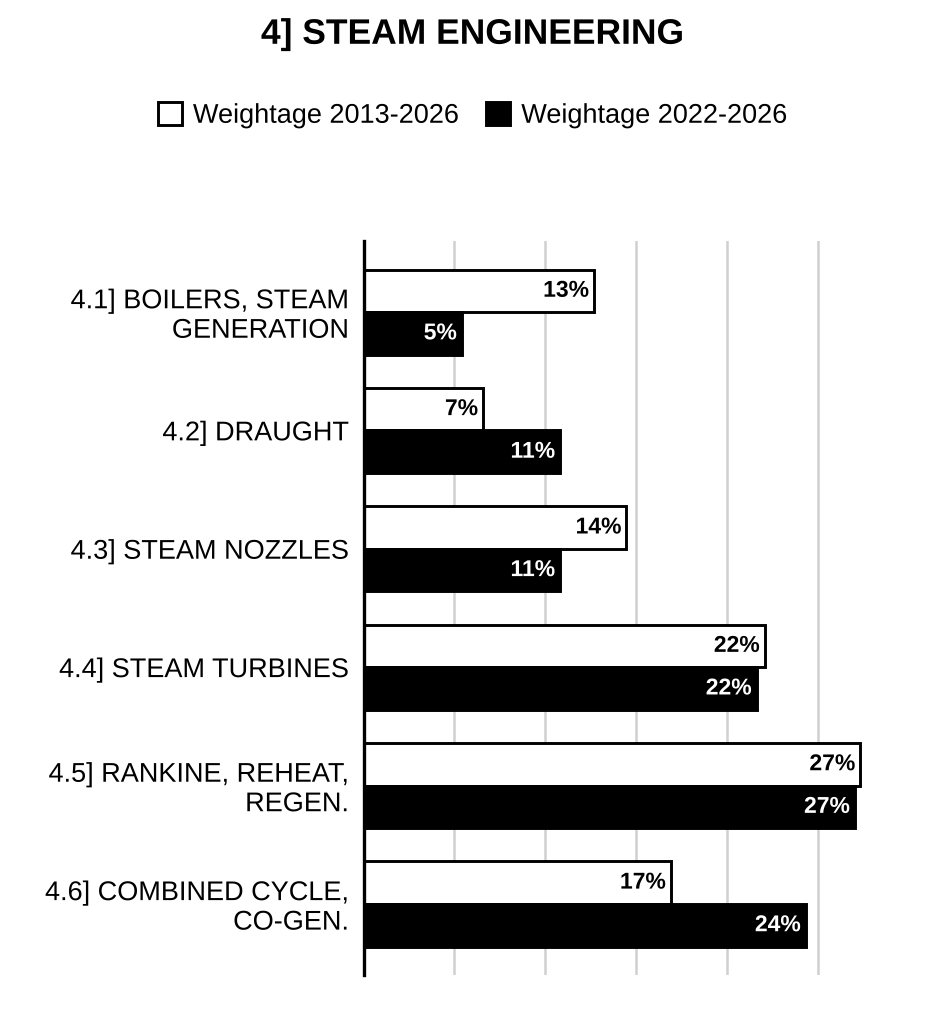
4.1] Steam generation and boilers
36 questions
What are the advantages and disadvantages of supercritical pressure boilers as compared to that of subcritical boilers? Also, draw the Rankine cycle (T-s diagram) for a steam power plant employing supercritical boiler with single stage of reheating. [2025/10m/5c]
Explain the functions of three types of superheaters used in power boilers. Sketch the heat addition process in them on a T-s chart. Also mention the function of desuperheater (or attemperator). [2024/10m/5a]
The flue gas composition measured by Orsat apparatus for a boiler burning a fuel of unknown hydrocarbon is given as follows: : 8.0%, CO: 0.9%, : 8.8% and : 82.3% Determine (i) the composition of the fuel (ii) the air fuel ratio on mole and mass basis (iii) the percentage of excess air used. [2021/10m/5b]
Compare the thermal efficiencies of two boilers having the following data: Boiler 1 (Coal-fired): Steam pressure–1.4 MPa Steam produced/kg of coal fired–10 kg Quality of steam–0.9 Feed water temperature–27 °C Calorific value of coal–34000 kJ/kg Boiler 2 (Oil-fired): Steam pressure–1.4 MPa Steam produced/kg of oil fired–14 kg Condition of steam (superheated)–240 °C Feed water temperature–27 °C Calorific value of oil–46000 kJ/kg Use the following data: At 1.4 MPa for steam– kJ/kg at 240 °C kJ/kg kJ/kg Specific heat of feed water = 4.1868 kJ/kg-K. [2019/10m/7b(ii)]
Define steam, quality and derive expression for specific volume of steam in terms of steam quality. [2017/10m/1e]
Classify different types of boilers and discuss factors important for the boiler selection. [2017/10m/2c]
Discuss experimental determination of calorific value of solid fuel with a neat diagram. [2017/10m/5c]
A sample of fuel was found to have the following percentage analysis by weight: C 80; 16; and ash etc. 4. Determine the minimum weight and volume of air required to burn 1 kg of this fuel. Density of is 1.429 kg/m³. [2017/10m/5e]
What is the function of an economiser in a thermal power plant? Why are the economiser tubes often provided with fins on the gas side? Explain. [2016/10m/5b]
Propane () is burned with 100% excess air in an adiabatic burner. Both the fuel and air enter the burner at 25°C and 1 bar. Estimate the maximum temperature that can be attained in the flame. The molar heat capacities of the product gases are as follows: Here is in J/mol. K and T is in K. Assume standard heat of this reaction as . [2015/10m/1e]
What is an Orsat apparatus? Draw a neat diagram of Orsat apparatus and explain its functioning. [2015/10m/5e]
Explain with a sketch how heat is absorbed at various stages from feed water to steam generation in water tube boilers. [2015/15m/8c]
The products of combustion of an unknown fuel have the following composition as measured by an Orsat apparatus: Determine the values of x and y, the air-fuel ratio and % of excess air used. [2014/10m/5a]
A boiler receives a flow of 5000 kg/hr liquid water at 5 MPa, 20°C and it adds energy to the flow to exit state of 450°C, 4.5 MPa. Determine the necessary minimum pipe flow area for inlet and outlet pipes. The velocity of water is maintained under 20 m/s. If this boiler is to operate on Moon, discuss two major design changes in this type of boiler. Given properties of water: [2012/12m/1d]
(i) Mention the unique features of modern high pressure boiler and describe the operation of Lamont boiler with a sketch. (ii) Representing on h- diagram, explain supersaturated expansion of steam in a nozzle. Indicate Wilson line on diagram and state effects of supersaturation. [2011/10m/4c]
(i) With the help of a sketch discuss the working principle of a high pressure Benson boiler with advantages. (ii) Discuss the purpose of drum used in boiler and show internal details for mechanism of separation of moisture in drum. [2010/20m/5b]
In what way is Velox boiler different from La Mont boiler? Describe the working of the Velox boiler with a schematic. [2009/20m/5c]
Draw a schematic of a Benson boiler and explain its working principle, pointing out its speciality. [2009/20m/6b]
Draw a schematic diagram of bubbling bed fluidized boiler and explain its working. [2009/15m/7b]
Explain with a neat diagram the working of a supercharged boiler. What are its advantages over conventional boilers? Why economizers are essentially used irrespective of the fuel used in boiler furnace? [2008/20m/5b]
A superheater is to be designed using metallic coils (heat flux ) of inside diameter 50 mm and wall thickness 5 mm. The steam leaving the superheater coils is at 60 bars, 500°C and flows at a velocity of 10 m/s. If the steam mass flow rate is 90 kg/s, find the number and length of coils. For steam at 60 bars, take the following values-dry saturated steam h = 2784.3 kJ/kg, at 500°C superheated steam temperature = 3422.2 kJ/kg and specific volume . The steam enters the superheater as dry and saturated. [2006/20m/5d]
Discuss the trends in the design of modern power plant boilers. Explain the zones of heat transfer and location of evaporators, super heaters and reheater. [2003/20m/200w/5d]
The actual amount of air supplied per kg of a fuel can be ascertained from the measured composition by volume of combustion products. Describe an apparatus to do the needful. [2002/20m/200w/1c]
Discuss the difference between natural circulation, forced circulation and once-through boilers. Explain, with the help of a sketch, the working of a La Mont boiler. [2002/30m/7b]
Clearly explain as to how the circulation is maintained in modern boilers having operating pressures 100 bar, 180 bar and 240 bar respectively? What is circulation ratio? What is the normal range of circulation ratio in case of utility boilers and industrial boilers? [2001/30m/8b]
Explain what is meant by Higher and Lower Calorific Value of a fuel. Describe with the help of a neat sketch the principle and working of an apparatus used for determining the calorific value of a gaseous fuel. [2000/20m/3a]
An oil fired boiler uses 52 kg/hr of oil having a higher calorific value of 44900 kJ/kg and composition/kg C = 0.847, = 0.13, S = 0.0125 and generates 635 kg of steam/hr at 10.5 bar pressure from feed water supplied at 338 K. The flue gases having dry gas analysis/unit volume = 0.043. = 0.124, = 0.833 and specific heat 1.005 kJ/kg-K, leave the boiler at 635 K. The pressure and temperature of steam after throttling in a throttling calorimeter is 1.15 bar and 398 K respectively. Taking the partial pressure of steam in flue gases as 0.07 bar and the specific heat of superheated steam = 2.1 kJ/kg-K determine – (i) the equivalent evaporation / kg of fuel; (ii) boiler efficiency. Draw up a complete heat balance sheet. Take boiler room temperature = 234 K. [2000/40m/8b]
Give a schematic diagram of a modern large capacity high pressure boiler and discuss its special features. What is the advantage of providing both convective and radiative superheaters in the boiler plant? [1999/20m/6a]
Show that the mass of air, , supplied for the combustion of 1 kg of fuel of known carbon content, C%, can be determined from the volumetric analysis of dry products of combustion using where , and CO are the percentages by volume of gases nitrogen, carbon dioxide and carbon monoxide respectively. [1998/30m/4a]
Coal having the following composition is burnt in a furnace: Carbon 86.1%, Hydrogen 3.9%, Oxygen 14% rest ash. The volumetric analysis of dry products was: = 12.7%, CO = 1.4%, = 4.1%, = 81.8%. Determine the percentage of excess air. Also determine the loss due to incomplete combustion, if CO burning to will release 24000 kJ/kg of carbon in CO. [1998/30m/4b]
During a boiler trial, steam was produced at a pressure of 20 bar and superheat temperature of 360 °C using feed water at 30 °C at the rate of 90,000 kg/hr. Coal with 3% moisture having calorific value of 34,000 kJ/kg of dry coal was burnt at the rate of 1000 kg/hr. The temperature of flue gases at the exit was 200 °C while inlet air was at 30 °C. Coal contains 80% carbon, 6% hydrogen and rest ash. Volumetric analysis of dry flue gases is: = 12%, = 10% and = 78%. Enthalpy of steam at 20 bar, 360 °C = 3159.3 kJ/kg, enthalpy of water at 30 °C = 126 kJ/kg. In the flue gas, the enthalpy of steam at exit condition is 2879.7 kJ/kg. Specific heat of gas = 1.01 kJ/kg. Draw the heat balance sheet. [1998/30m/8b]
Describe the method of determining calorific value of a solid fuel using a Bomb calorimeter, the following results were recorded during evaluation of a coal sample: Mass of coal 1 gm; Mass of water in calorimeter 2500 gm; Water equivalent of apparatus 744 gm; Initial temperature of water 17.48° C; Maximum observed temperature of water 20.07° C; Specific heat of water 4.187 J/g°C. What are the calorific values of this fuel? [1997/20m/200w/1d]
What are the special features in the design of high pressure high duty boilers? Discuss the advantages and disadvantages of forced circulation boilers as compared to natural circulation boilers. [1996/20m/200w/5a]
During the trial of coal fired boiler plant producing steam at 40 bar pressure and 350°C temperature, the steam produced per kg of coal fired was found to be 9.18 kg. The dry coal analysis gave 84% carbon, 4% hydrogen, 7% oxygen and 5% ash. Moisture is coal used was 1.5%, carbon in ash was nil. The calorific value of dry coal was 32700 kJ/kg. The volumetric analysis of dry flue gases gave 12.3% carbon dioxide, 7.7% oxygen and 80% nitrogen. The feed water temperature at entry to economiser was 27° C and that at exit 150°C. The temperatures of flue gas entering and leaving air pre-heater were 280°C and 160°C respectively while temperature of air leaving preheater was 110°C and at entry 15°C. Determine (i) boiler efficiency, (ii) efficiency of heat transmission in air heater. Draw up a heat balance for the complete boiler plant in kJ/kg of dry coal using a datum of 15°C. Take for air and dry flue gas as 1.005 kJ/kg°C, partial pressure of steam vapour and its specific heat as 0.07 bar and 2.01 kJ/kg°C respectively. [1996/60m/8]
The volumetric percentages of , CO and in the dry flue gas from a boiler using fuel containing C per cent of carbon are X, Y and Z respectively. Show that the quantity of excess air R per kg of fuel burnt can be expressed in the form. Determine the value of the numerical constant K. [1995/20m/8a]
A boiler with economiser uses coal having the following gravimetric composition: C = 84% = 4.5% = 3.5%, Moisture = 1% Ash = 7%. The percentage volumetric composition of the flue gas when entering and leaving the economiser was found to be.
| CO | ||||
| Entering | 8.28 | 0.42 | 11.40 | 79.90 |
| Leaving | 6.95 | 0.35 | 12.95 | 79.75 |
Determine per 100kg of fuel fired: (a) the mass of the flue gas (including moisture) entering the economiser; (b) the leakage of air into the economiser; (c) the loss of heat due to imperfect combustion. Calorific value of carbon when burnt to is 8100 kcal/kg and when burnt to CO is 2430 kcal/kg. Air contains 23 per cent by weight of . [1995/40m/8b]
4.2] Draught
14 questions
A chimney of 35 m height is discharging the flue gases at 300 °C, when the ambient temperature is 25 °C. The quantity of air supplied is 16 kg per kg of fuel burnt. Determine the– (i) draught produced in mm of water; (ii) equivalent draught in metres of hot gas column; (iii) efficiency of the chimney, if the minimum temperature of artificial draught is 120 °C and the mean specific heat of hot flue gases is 1.005 kJ/kg-K; (iv) percentage of heat spent in natural draught system, if the net calorific value of the fuel is 33000 kJ/kg. [2026/10m/8c]
Derive the expression as given below for draught h in mm of water column being created by a chimney of height H metre: where is mass of air supplied per kg of fuel, and and are ambient air and hot gas temperatures in Kelvin, respectively. [2025/10m/5d]
A process industry employs a medium pressure boiler to produce steam. The mass flow rate of fuel consumed is 0.847 kg/s and c.v. of the fuel is 44 MJ/kg. For efficient combustion, 16 kg of air per kg of fuel is required, for which a draught of 30 mm of the water column is required at the base of the chimney. The flue gases leave the boiler at 350 °C. The average temperature of gases in the stack may be taken as 300 °C. The atmosphere is at 20 °C. Assuming the velocity of gases at the stack exit to be negligible, determine the height of the stack and the diameter at its base. Also, calculate the mass flow rate of the gases. Take kPa, kJ/kg-K, , . [2023/10m/8c]
Prove mathematically that for maximum discharge through a chimney of a certain height and cross-section, the absolute temperature of gases bears a certain ratio to the absolute temperature of the outside atmosphere, in case of natural draught of a boiler. [2022/10m/7c]
Determine the height of a chimney to produce a static draught of 20 mm of water. The mean hot gas temperature in the chimney is 270 °C and the atmospheric air temperature is 20 °C. Take atmospheric pressure as 0.101325 MPa. The characteristic gas constant for air is 287 J/kg-K and for chimney gas, it is 255 J/kg-K. [2019/10m/5b]
Determine the expression for the ratio of chimney gas temperature to outside air temperature in terms of mass flow rate. [2014/10m/5b]
Hot gases inside a chimney are at 430 °C and the chimney height is 32 metres. The temperature of outside air is 28 °C. The furnace is supplied with 17 kg of air per kg of coal burnt. Calculate– (i) draught in mm of water; (ii) draught height in metres of hot gases. [2013/10m/5c]
State the factors affecting the amount of draught produced in the boiler and discuss merits and demerits of induced draught system with reference to: (i) boiler efficiency, (ii) fan maintenance, (iii) power to drive the fan, (iv) leakages. [2011/10m/3c]
The following data relate to a boiler using induced draught system: Length of the duct carrying flue gases 150 m Mean size of the square duct 75 Mean flue gas velocity in the duct 900 m/min Mean temperature of gases passing through duct 227°C Plenum pressure 15 cm of water Atmospheric pressure 75 cm of Hg Number of 90° bends 4 Number of 45° bends 4 Loss of draft in every 90° bend 0.1 cm of water Draft available from chimney 1.5 cm of water Fuel bed resistance for underfired stoker 10 cm of water Fan efficiency 60% Motor efficiency driving fan 92.5% Characteristic gas constant for gases 294 kJ/kg-K Friction factor, f, corresponding to round section duct 0.006 Assuming that a 45° bend equal one-half of 90° bend and that the resistance offered by square duct is 20% greater than a similar round duct, determine: (i) Draft to be produced due to friction in square cross-section duct in mm of water. (ii) Draft due to velocity head of flue gases in mm of water. (iii) Total draft for the boiler. (iv) Draft to be produced by induced fan. (v) Power required to drive fan. [2011/30m/8a]
In a steam power plant, the steam generator generates steam at the rate of 120 t/h at a pressure of 100 bar and temperature of 500 °C. The calorific value of fuel used by steam generator is 41 MJ/kg with an overall efficiency of 85%. In order to have efficient combustion, 17 kg of air per kg of fuel is used for which a draught of 25 mm of water gauge is required at the base of stack. The flue gases leave the steam generator at 240 °C. The average temperature of gases in the stack may be taken as 200 °C and the atmospheric temperature is 30 °C. Work out the following: (i) The height of stack required. (ii) The diameter of stack at its base. (iii) Draw the draught distribution considering balanced draught system in a steam generator and mention the advantages of balanced draught. Take the following steam properties for solution: , . [2010/20m/7a]
How do you classify draught? What are the advantages of the forced draught over the induced draught? What are the limitations of chimney draught? What are the different losses taken into consideration in designing the draught system? [2008/20m/5a]
From the following data for the underfeed stoker boiler, find draft required in mm of water column and power required to drive the fan:
| Mean temperatures of flue gases passing through duct | 227 °C |
| Plenum pressure | 15 cm of water |
| Atmospheric pressure | 75 cm of Hg |
| Mean velocity of flue gases in duct | 900 m/min |
| Length of the duct | 150 m |
| Mean size of the non-circular duct | |
| Number of 90° bends | 4 |
| Number of 45° bends | 4 |
| Loss of draft in every 90° bend | 0.1 cm of water |
| Draft available from chimney | 1.5 cm of water |
| Fuel bed resistance for underfeed stoker | 10 cm of water |
| Fan efficiency | 60% |
| Motor efficiency | 92.5% |
Assuming that 45° bend is equivalent to one-half of 90° bend, resistance offered by non-circular duct is 20% higher than a similar circular duct, friction factor for circular duct is 0.006, find draft required to be produced by fan and the fan power for flue gases. Take R = 294.35 J/kg-K. [2007/40m/7b]
A forced draught fan discharges 1200 of air per minute through the outlet of 2 area and maintains a steady pressure of 110 mm of water. The temperature of air is 27°C. Calculate the power of the motor to drive the fan if the efficiency of the fan is 85%. Take the density of air at 27°C as 1.25 [?]. [2002/20m/200w/5d]
Explain the terms forced draft, induced draft and balanced draft, and discuss their relative merits and demerits. What is the role of a chimney in a boiler? Why no chimney is provided in a locomotive boiler? [2000/20m/8a]
4.3] Steam nozzles
15 questions
Describe the behaviour of steam flow in a convergent nozzle when it is operated at– (i) design pressure ratio; (ii) pressure ratio higher than the design value; (iii) pressure ratio lower than the design value. [2026/10m/5c]
Calculate the critical pressure and throat area per unit mass flow rate of a convergent-divergent nozzle, expanding steam from 10 bar and dry saturated, down to atmospheric pressure of 1 bar. Assume that the inlet velocity is negligible and that the expansion is isentropic. Use Steam tables given at the end to get the steam data. The value of isentropic expansion index may be taken as 1.135. [2025/10m/8c]
A convergent-divergent nozzle receives steam at 5 bar, 250 °C and expands it isentropically into a space at 1 bar. Neglecting the inlet velocity, calculate the exit area required for a mass flow of 0.5 kg/s for the following cases: (i) When the flow is in equilibrium (ii) When the flow is supersaturated with = constant Given, at 5 bar, 250 °C , kJ/kg-K, kJ/kg and at 1 bar , kJ/kg, kJ/kg kJ/kg-K, kJ/kg-K. [2023/20m/7a]
Describe the following terms with reference to stream nozzle: (i) Efficiency () (ii) Velocity coefficient () [2021/10m/5c]
(i) A single stage impulse steam turbine rotor has a diameter of 1.2 m and runs at 3000 rpm. The nozzle angle is 18°. The blade speed ratio is 0.42. The relative velocity at the outlet to the relative velocity at inlet is 0.9. The outlet angle of the blade is 3° smaller than the inlet angle. For a steam flow rate of 10 kg/s find Blade angles at inlet and outlet, Axial thrust on the bearing and Power developed. (ii) Describe the phenomenon of super saturated flow observed in steam nozzle using T-s diagram. How does it influence the mass flow rate through the nozzle? [2021/20m/7a]
The mass flow rate of steam flowing in a pipeline is measured with the help of a well-insulated Venturi meter. Dry saturated steam at 7.0 bar enters the Venturi. The pressure at the throat of the Venturi is measured to be 3.6 bar. The inlet and throat diameters of the Venturi are 538.5 mm and 75 mm respectively. The velocity of steam at the inlet to the Venturi is 10 m/s. Calculate the mass flow rate of steam neglecting friction. (The properties of steam are to be taken from the steam table as given below): Properties of Saturated Steam.
| Pressure, P (bar) | (°C) | Specific volume (m/kg) | Specific volume (m/kg) | Specific enthalpy (kJ/kg) | Specific enthalpy (kJ/kg) | Specific entropy (kJ/kg-K) | Specific entropy (kJ/kg-K) |
| 3.6 | 140.0 | 0.00108 | 0.511 | 588.6 | 2733.7 | 1.738 | 6.931 |
| 7.0 | 165.0 | 0.001108 | 0.273 | 697.2 | 2763.5 | 1.992 | 6.708 |
[2020/20m/2b]
(i) Discuss the effect of variation of back pressure on mass flow rate and pressure distribution in a convergent-divergent nozzle. (ii) What do you mean by supersaturated flow of steam in nozzles? [2018/20m/7b]
A convergent-divergent nozzle receives steam at 5.0 bar, 200 °C and expands isentropically into a space at 2.0 bar. Neglecting the inlet velocity, calculate the exit area required for a mass flow of 0.3 kg/s in the following cases: (i) When the flow is in equilibrium throughout (ii) When the flow is supersaturated with = constant Calculate also for this supersaturated flow, the degree of supercooling and the degree of supersaturation. Properties of steam: At 5.0 bar and 200 °C, , , At 2.0 bar and , , , , , , [2016/20m/6b]
Which are the factors effecting Nozzle efficiency? [2015/4m/5c(ii)]
Dry saturated steam at 5 bar enters a convergent-divergent nozzle at a velocity of 100 m/s. The exit pressure is 1.5 bar. The throat and exit areas are and respectively. Assuming isentropic flow upto the throat and taking the critical pressure ratio as 0.58, estimate the mass flow rate. If the nozzle efficiency is 0.973, determine the exit condition of steam dryness fraction. Show the process on T-s and h-s diagrams. Properties of Steam.
| P (bar) | Enthalpy (kJ/kg) | Enthalpy (kJ/kg) | Entropy (kJ/kg K) | Entropy (kJ/kg K) | Volume () | Volume () |
| 5.0 | 640.23 | 2108.5 | 1.8607 | 4.9606 | 0.00109 | 0.3708 |
| 2.9 | 556 | 2168 | 1.660 | 5.344 | 0.00107 | 0.6253 |
| 1.5 | 467.11 | 2226.5 | 1.4336 | 5.7897 | 0.00105 | 1.158 |
[2015/20m/7c]
Derive an expression for critical pressure ratio of a nozzle. Explain the phenomenon of choking in the nozzle. [2014/10m/7a(i)]
Steam enters a nozzle operating at steady state at 40 bars, and 400°C and 10 m/s. Steam flows through this nozzle with negligible heat transfer and change in potential energy. Steam exits at 15 bars and 665 m/s. Mass flow rate is 2 kg/s. Compute exit area of the nozzle. Given data for steam at 15 bar:
| T(°C) | h(kJ/kg) | V() |
| 250 | 2923.9 | 0.15201 |
| 300 | 3038.2 | 0.16971 |
and Enthalpy of steam at inlet 3214.5 kJ/kg. [2011/20m/2b]
(i) Mention the unique features of modern high pressure boiler and describe the operation of Lamont boiler with a sketch. (ii) Representing on h- diagram, explain supersaturated expansion of steam in a nozzle. Indicate Wilson line on diagram and state effects of supersaturation. [2011/10m/4c]
(i) Derive the following expression for the critical pressure ratio () in a steam nozzle where steam enters with initial velocity and the flow is accompanied with friction: where: = initial steam velocity, = initial steam pressure, = small stage expansion efficiency , = actual exponent of expansion, = initial steam specific volume. (ii) Show the effect of variation of back pressure on distribution of pressure and velocity all along in a convergent-divergent nozzle. [2010/20m/6c]
Explain supersaturated flow in steam nozzles with the help of skeleton Mollier diagram inserting nomenclatures like dry saturated line, Wilson line and supersaturated zone. List also the five effects of supersaturation in the steam nozzles. [2009/20m/6c]

Preparing for Prelims too?
Our UPSC Prelims Topic-wise PYQ eBook covers every Prelims question with detailed explanations, so you can see exactly where UPSC asks from.
View the BookDownload Free Sample4.4] Steam turbines
27 questions
A single-row impulse steam turbine with a blade speed of 200 m/s and mass flow rate of 4 kg/s develops 300 kW of power. Steam leaves the nozzle at 500 m/s and the blade velocity coefficient is 0.92. If the steam leaves the turbine at such an angle that the exit absolute velocity is kept minimum, determine all the angles and diagram efficiency. Draw compound velocity triangles. [2026/20m/6b]
For special cases of axial flow reaction turbines with degree of reaction in the form , where k is an integer, a special relationship exists between the blade velocity ‘u’ and fluid inlet velocity or velocity for maximum utilization. Show that this relationship is given by ‘’. Here ‘’ is angle between inlet velocity ‘’ and blade velocity ‘u’. [2024/10m/1d]
Explain using neat sketches any two types of governing used in steam turbines. [2024/10m/6c]
(i) Draw typical velocity triangles of a stage of a reaction turbine, clearly showing the various velocities. (ii) Derive an expression to show that the optimum value of , the blade-to-steam speed ratio for a Parsons reaction turbine is given by , where is the inlet angle of the fixed blades. (iii) Also, show that the maximum efficiency of the Parsons reaction turbine is given by (iv) Draw the velocity triangles of the Parsons reaction turbine operating at . [2023/20m/6b]
A single-stage impulse turbine rotor has a mean blade ring diameter of 500 mm and rotates at a speed of 10000 r.p.m. The nozzle angle is 20° and the steam leaves the nozzles with a velocity of 900 m/s. The blades are equiangular and the blade friction factor is 0.85. Construct velocity diagrams for the blades and determine the inlet angle of the blades for shockless entry of steam. Also, determine (i) the diagram power for a steam flow of 750 kg/hr, (ii) the diagram efficiency, (iii) the axial thrust and (iv) the loss of kinetic energy due to friction. [2022/20m/4a]
(i) A single stage impulse steam turbine rotor has a diameter of 1.2 m and runs at 3000 rpm. The nozzle angle is 18°. The blade speed ratio is 0.42. The relative velocity at the outlet to the relative velocity at inlet is 0.9. The outlet angle of the blade is 3° smaller than the inlet angle. For a steam flow rate of 10 kg/s find Blade angles at inlet and outlet, Axial thrust on the bearing and Power developed. (ii) Describe the phenomenon of super saturated flow observed in steam nozzle using T-s diagram. How does it influence the mass flow rate through the nozzle? [2021/20m/7a]
Compare the throttling processes happening at the following two locations in the steam power plant and using T-s diagrams contrast the observed phenomena: (i) throttling of steam at inlet to turbine for governing. (ii) throttling of condensate in closed feed heater trap exit. [2021/10m/8c]
One stage comprising a pair of blade rings of a 50 percent reaction axial flow steam turbine has a mean ring diameter of 140 cm. The blade to steam speed ratio is 0.7. The speed of rotation is 3000 r.p.m. Determine the required entrance angle for the blading if the exit angle is 20°. Also, determine the work done per kg of steam flowing per second and the diagram efficiency. Calculate the percentage increase in diagram efficiency if the blades are designed for, and run at the best theoretical speed corresponding to the optimum operating condition, for the given steam speed and the exit angle. [2020/20m/3a]
A Parson’s turbine runs at 400 r.p.m. and it develops 75 kW of power per unit mass of steam flow per second. The exit angle of the blades is 20° and the steam velocity is 1.4 times the blade velocity. Find the blade velocity and the inlet angle of the blades. [2019/20m/6a]
Discuss the principle of bypass governing in a steam turbine with neat sketches. [2019/10m/8b(ii)]
The data pertaining to an impulse turbine are as follows: Blade speed = 300 m/s Isentropic enthalpy drop in nozzles = 450 kJ/kg Nozzle efficiency = 0.9 Nozzle angle = 20° Blade velocity coefficient = 0.85 Blade exit angle = 25° Sketch the velocity diagrams and calculate for a mass flow rate of 1 kg/s the following: (i) The inlet angle of moving blade (ii) The axial thrust (iii) The driving force on the wheel (iv) The diagram power (v) The energy lost in the blades due to friction. [2018/20m/6a]
The mean diameter of the blades of an impulse turbine with a single row wheel is 105 cm and the speed is 3000 rpm. The nozzle angle is 18°, the ratio of blade speed to steam speed is 0.42 and the ratio of the relative velocity at outlet from the blades to that at inlet is 0.84. The outlet angle of the blade is to be made 3° less than the inlet angle. The steam flow is 8 kg per sec. Draw the velocity diagram for the blades and estimate the (i) resultant thrust on the blades (ii) tangential thrust on the blades (iii) axial-thrust on the blades (iv) power developed in blades and (v) blade efficiency. [2017/20m/7a]
What is the function of a governor in a steam turbine? With the help of a neat sketch, explain the working of throttle governing. Show the process on h-s diagram. [2016/10m/7c]
The angles at inlet and discharge of the blading of a 50% reaction steam turbine are 35° and 20° respectively. The speed of rotation is 1500 rpm and at a particular stage, the mean ring diameter is 0.67 m, and the steam condition is 1.5 bar, 0.96 dry. Estimate (i) the required height of blading to pass 3.6 kg/s of steam, and (ii) the power developed by the ring. Assume, at 1.5 bar pressure, and . [2015/20m/6b]
At a stage in a reaction turbine, the pressure of steam is 34 kPa () and dryness fraction is 0.95. For a flow rate of 36000 kg/hr, the stage develops 950 kW. The turbine runs at 3600 r.p.m. and velocity of flow is 0.72 times the blade velocity. The outlet angles of both stator and rotor blades are 20°. Determine at this stage the mean rotor diameter and height of blades. [2014/10m/5c]
Even though velocity-compounded impulse turbines are less efficient, in the initial stages of high pressure turbines are normally velocity-compounded. Why? Plot the variation of pressure and velocities in velocity-compounded and pressure-compounded impulse turbines. [2014/10m/8b]
What do you understand by governing of steam turbine? Explain the principle and working of throttle governing with the aid of a neat sketch. Compare the throttle governing with nozzle control governing with following aspects: (i) losses, (ii) use. Sketch the efficiency against load with throttle governing. [2011/10m/2c]
(i) Derive the expression for optimum ratio for blade velocity to steam velocity in the case of Parson’s reaction steam turbine with the sketch of blade shape of a stage and velocity triangles. (ii) Give a cylinder layout of a 500 MW steam turbine and explain the reasons of double flow cylinders used. [2010/20m/5c]
(i) Give a practical feed heating arrangement of a 660 MW steam power plant by showing steam and feed flow paths. Mention its special features. (ii) In low pressure steam turbine, steam is wet. With the help of velocity diagrams show the direction of flow of steam and water particles on moving blades and guide vanes so that the causes of erosion of blades get established. [2010/20m/8b]
Draw a schematic of a pass-out turbine and explain its working. Represent the relevant process on Enthalpy – Entropy coordinates. [2009/20m/5a]
The following observations refer to a surface condenser: Mass flow rate of condensate = 20 kg/min; Mass flow rate of cooling water = 800 kg/min; Mean temperature of condensation = 35° C; Condenser vacuum = 0.95 ; Barometer reading = 1.03 ; Inlet cooling water temperature = 20° C; Outlet cooling water temperature = 30° C; Temperature of the hot well = 29° C. Calculate: (i) Weight of air per unit volume of condenser. (ii) Entering condition of steam to the condenser. (iii) Vacuum efficiency of the condenser. Properties of saturated steam:
| T (°C) | P (MPa) | Sp. Vol. () | Sp. Vol. () | Enthalpy (kJ/kg) | Enthalpy (kJ/kg) | Entropy (kJ/kg.K) | Entropy (kJ/kg.K) |
| 35 | 0.0056 | 0.001 | 25.245 | 146.56 | 2565.4 | 0.5049 | 8.3543 |
(Use ) [2009/25m/7c]
A reaction turbine having identical blading delivers dry saturated steam at 3 bar. The velocity of steam is 100 m/sec. The mean blade height is 40 mm and the exit angle of the moving blade is 20°. At the mean radius, the axial flow velocity equals 3/4th of blade speed. For a steam flow rate of 10,000 kg/hr, determine: (a) the rotor speed in rev/min, (b) the power output of stage, (c) the diagram efficiency, (d) the percentage increase in relative velocity in the moving blade due to expansion in these blades and (e) The enthalpy drop of steam in the stage. Specific volume of dry saturated steam at 3 bar is . [2008/35m/8c]
Derive an expression for the blade efficiency of a single row impulse steam turbine assuming equiangular blades in terms of nozzle angle , blade velocity coefficient K and blade speed ratio. If and K = 0.9, what is the maximum blade efficiency and corresponding blade angles? If the blade efficiency is 85% of the maximum value, what are the possible blade speed ratios for the same nozzle angle , blade velocity coefficient, K and equiangular blades? Also, find the corresponding blade angles. [2003/30m/8b]
Steam expands in a steam turbine isentropically from inlet to exhaust having an enthalpy drop = 1200 kJ/kg. Assuming ideal conditions, determine the mean diameter of the wheel if the turbine were of (i) single impulse stage, (ii) single 50% reaction stage, (iii) one two-row Curtis stage and (iv) ten 50% reaction stages. Take the nozzle angle as 18° and blade speed as 4000 rpm. [2002/30m/8a]
Show that in a 50% reaction turbine stage, the maximum stage efficiency is given by, where, α is the nozzle angle. [2001/20m/200w/1d]
The velocity of steam entering a simple impulse turbine is 1000 m/s and the nozzle angle is 20°. The mean peripheral velocity of blades is 400 m/s. The blades are asymmetrical. If the steam is to enter the blades without shock, that will be the blade angles? Neglecting the friction effects on the blades, calculate the tangential force on the blades and the diagram power for a mass flow of 0.75 kg/s. Calculate the axial thrust and diagram efficiency. [2001/30m/8a]
At a particular stage of a reaction turbine the mean blade speed is 140 m/s and the steam is at a pressure of 20 bar with a temperature of 250° C. Fixed and moving blades at this stage have inlet angles 30° and exit angles 20°. The stage efficiency is 80%. Determine (i) the specific enthalpy drop across the stage in kJ/kg. (ii) the drum diameter and blade height of the blade height is one-twelfth of the drum diameter and the steam flow is 120 kg/s. (iii) the percentage increase in relative velocity across the bladings as a result of the pressure drop across the blading. [1999/30m/8b]
4.5] Rankine cycle, reheat and regeneration
33 questions
An ideal regenerative steam power cycle operates so that steam enters the turbine at 30 bar and 350 °C, and exhausts at 0.1 bar. A single open feedwater heater is employed which operates at 5 bar. Compute the thermal efficiency of the cycle. The steam properties at 30 bar and 350 °C are kJ/kg and kJ/kg-K. Use Steam tables given at the end to get other properties.
[Attached: Steam tables supplied at the end of the paper (not transcribed), headed “For Question Nos. 6(b), 7(a) and 8(c)”: “Steam Table [Saturated Water : Pressure]” on page 21, continued on pages 22–23 (printed rotated), giving pressure, saturation temperature, specific volume, internal energy, enthalpy and entropy of saturated liquid, evaporation and saturated vapour.] [2025/20m/6b]
A steam power plant operates with a boiler output of 20 kg/s steam at 2 MPa and 600°C. The condenser operates at 50°C, dumping energy into a river that has an average temperature of 20°C. There is an open feed heater with extraction from the turbine at 600 kPa, at its exit is saturated liquid. Find the mass flow rate of the extracted flow (liquid). If the river water should not be heated more than 5°C, how much water should be pumped from the river to the heat exchanger (condenser)? The steam properties at 2 MPa, 600°C are: h = 3690.14 kJ/kg s = 7.7023 kJ/kg K At 600 kPa and for s = 7.7023 kJ/kg K, take h = 3270.25 kJ/kg. Use the Steam Tables given at the end to get other properties. [2024/20m/7b]
What are the desirable characteristics of an ideal working fluid for vapour power cycle? [2023/10m/5b]
What is reheat factor of a steam turbine? Derive an expression to show that the reheat factor is always greater than unity. [2023/10m/5c]
Using a schematic and T-s diagram, explain how with perfect regeneration for a simple steam power plant (Rankine) cycle, thermal efficiency can approach Carnot efficiency. [2022/10m/5c]
A power plant operates on a regenerative steam cycle with one closed feedwater heater. Steam enters the first turbine stage at 125 bar, 500 °C and expands to 10 bar, where some of the steam is extracted and diverted to the closed feedwater heater. Condensate exiting the feedwater heater as saturated liquid at 10 bar passes through a trap into the condenser. The feedwater exits the heater at 120 bar with a temperature of 170 °C. The condenser pressure is 0.06 bar. Assuming isentropic turbine and pump work, determine the thermal efficiency of the cycle. At 125 bar, 500 °C for steam, kJ/kg and kJ/kg-K. [Use steam tables provided at the end of this Paper]. [2022/20m/6b]
Two vapor power cycles are coupled in series where heat lost by one is absorbed by the other completely. If is the thermal efficiency of the topping cycle and is the thermal efficiency of the bottom cycle, determine the efficiency of the combined cycle in terms of these efficiencies. Assume cycles to be reversible. [2022/10m/8c]
In a single-heater regenerative cycle the steam enters the turbine at 30 bar, 400°C and the exhaust pressure is 0.1 bar. The feed water heater is a direct-contact type which operates at 0.3 MPa. Find the efficiency of the cycle neglecting pump work. (At 30 bar, 400°C: h = 3230.9 kJ/kg and s = 6.9212 kJ/kg K. Also use steam tables given towards the end of booklet for steam/water properties). [2021/20m/6b]
Compare the throttling processes happening at the following two locations in the steam power plant and using T-s diagrams contrast the observed phenomena: (i) throttling of steam at inlet to turbine for governing. (ii) throttling of condensate in closed feed heater trap exit. [2021/10m/8c]
When does reheating of steam become necessary in Rankine cycle? With the help of T-s diagram, explain the effect of reheating on the Rankine cycle output and efficiency. [2020/10m/1e]
Mention the desirable characteristics of the working fluid in a steam power plant. [2018/10m/5b]
Explain how the ideal regenerative cycle may approach to Carnot cycle efficiency. Also, mention the reason as why ideal regenerative cycle cannot be achieved in practice. [2018/20m/8b]
Define overall efficiency, boiler efficiency, cycle efficiency, mechanical efficiency and generator efficiency of a Rankine cycle based power plant and also prove that: [2017/10m/6b(ii)]
What are the desirable properties of a fluid for use as a working substance in Rankine cycle based heat engine plant? Discuss with the help of T-s diagram. [2016/10m/5c]
A cyclic steam power plant is to be designed for a steam temperature at turbine inlet of 360 °C and an exhaust pressure of 0.08 bar. After isentropic expansion of steam in the turbine, the moisture content at the turbine exhaust is not to exceed 15%. Determine the greatest allowable steam pressure at the turbine inlet, and calculate the Rankine cycle efficiency for these steam conditions. Estimate also the mean temperature of heat addition. Compare the Rankine cycle efficiency with the Carnot cycle efficiency operating between the mean temperature of heat addition and the condenser temperature. Neglect the pump work input. Properties of steam: At bar and , , , , [2016/20m/8c]
A steam power plant, working on Rankine cycle has constant steam temperature. The condenser pressures are 25, 50 and 75 mm of Hg and inlet steam pressure varies from 20 to 160 bar. Explain with the help of performance curve and reason how the thermal efficiency will vary. [2015/6m/5c(i)]
A steam power station uses the following cycle: Steam boiler outlet 150 bar, 550 °C (, ); Reheat at 40 bar to 550 °C (, ); Condenser at 0.1 bar (, , , ) Assuming ideal processes, find quality of steam at turbine exhaust, cycle efficiency and steam flow rate per kWh. [2014/10m/7a(ii)]
A steam power plant operates on ideal regenerative Rankine cycle. Steam enters the turbine at 6 MPa, 450 °C (, ) and is condensed in the condenser at 20 kPa (, , , , ). Steam is extracted from the turbine at 0.4 MPa (, , , , ) to heat feedwater heater. Water leaves feedwater heater as saturated liquid. Show the cycle on T-s diagram and find net work output/kg of steam, the boiler and thermal efficiencies of the cycle. [2014/20m/8c]
With the help of T-s diagrams, differentiate between Carnot and Rankine vapour cycles. State the advantages of Rankine cycle and derive the expression for its thermal efficiency. [2013/15m/7a]
A combined cycle power plant operates with mercury and steam cycles. Mercury cycle is superimposed over the steam cycle operating between boiler outlet condition of 40 bar and 400 °C ( and ) and condenser temperature of 40 °C. The heat released by mercury condensing at 0.2 bar is used to impart the latent heat of vaporization to the water in steam cycle. Mercury turbine receives mercury as saturated vapour at 10 bar. Calculate the mass of mercury circulated per unit mass of water and the efficiency of this binary cycle. Properties of saturated mercury and steam are:
| Fluid | P (bar) | T (°C) | Enthalpy (kJ/kg) | Enthalpy (kJ/kg) | Entropy (kJ/kg-K) | Entropy (kJ/kg-K) | Sp. vol. () | Sp. vol. () |
| Mercury | 10 | 515.5 | 72.23 | 363 | 0.1478 | 0.5167 | 0.0333 | |
| Mercury | 0.2 | 277.3 | 38.35 | 336.55 | 0.0967 | 0.6385 | 1.163 | |
| Steam | 0.074 | 40 | 167.5 | 2574.4 | 0.572 | 8.258 | 0.001 | 19.546 |
[2013/35m/7b]
A small power plant produces 25 kg/s steam at 3 MPa, 600°C in the boiler. It cools the condenser with ocean water coming in at 12°C and returned at 15°C. Condenser exit is 45°C. Find (i) net power output. (ii) required mass of ocean flow water. Given: [2012/20m/3a]
A designer is given the job of designing a steam based power plant to compete with a nuclear power plant. Sketch five cycles (all versions of Rankine cycle) that may qualify for such a job. Justify your answer with the notion that nuclear power is cheaper under the given steam-water conditions. [2012/20m/4b]
A low temperature power plant operates with a refrigerant maintaining – 20°C in the condenser, a pressure of 3 MPa and superheat of 80°C. There is one open feedwater heater operating at 800 kPa with an exit as saturated liquid at 0°C. (i) Sketch the schematic of this plant. (ii) Sketch the corresponding T – S diagram. (iii) Set up equations only to compute extraction fraction of the flow out of turbine and the turbine work per unit mass flowing through boiler. (iv) Indicate in your answer which refrigerant properties are needed. [2012/20m/8b]
A steam power plant runs on an ideal reheat-regenerative Rankine cycle. Details are given in Figure. Steam at turbine inlet is at 150 bars and 600°C. Condensor pressure is 0.10 bar. Steam exiting the HPT is at 40 bars. This steam is split in two parts, y and x. Part x is reheated at the same pressure to 600°C and sent to LPT. Part y is condensed completely in CFWH and it is pumped to 150 bars before it mixes with the flow at same pressure. A fraction of steam, z, is extracted from LPT at 5 bars. Assume steam output of boiler as 1 kg/s for ease of computations. Determine: (i) fraction y (ii) fraction z (iii) thermal efficiency of the cycle. Given data is: kJ/kg kJ/kg kJ/kg kJ/kg kJ/kg kJ/kg kJ/kg kJ/kg kJ/kg kJ/kg kJ/kg kJ/kg kJ/kg kJ/kg kJ/kg kJ/kg.
[Figure: Fig.: Schematic of steam power plant – Boiler B delivers steam (state ⑨) to the high pressure turbine HPT; the HPT exhaust (⑩) divides: one branch passes through the reheater R inside the boiler and goes (⑪) to the low pressure turbine LPT, the other branch goes down to the closed feedwater heater CFWH as heating steam; HPT and LPT are on a common shaft driving a generator; steam extracted from the LPT (⑫) goes to the open feedwater heater OFWH; the LPT exhaust (⑬) goes to the condensor C; condensate from C (①) is pumped by pump P1 (②) into the OFWH; the OFWH outlet (③) is pumped by P2 (④) through the tube coil of the CFWH, leaving as ⑤ to the mixing chamber MC; the condensed heating steam drained from the CFWH (⑥) is pumped by P3 (⑦) into the MC; the MC outlet (⑧) returns to the boiler B. Key: R – Reheater; B – Boiler; HPT – High pressure turbine; LPT – Low pressure turbine; C – Condensor; OFWH – Open feedwater heater; CFWH – Closed feedwater heater; MC – Mixing chamber; P1 – Pump 1; P2 – Pump 2; P3 – Pump 3] [2011/30m/4a]
A Rankine cycle based power plant is designed with superheat and reheat: (i) Sketch T-s diagram. (ii) Explain the effect of lowering/raising condensor pressure. (iii) Explain the effect of lowering/raising boiler pressure. [2011/15m/5c]
(i) Give a practical feed heating arrangement of a 660 MW steam power plant by showing steam and feed flow paths. Mention its special features. (ii) In low pressure steam turbine, steam is wet. With the help of velocity diagrams show the direction of flow of steam and water particles on moving blades and guide vanes so that the causes of erosion of blades get established. [2010/20m/8b]
With the help of schematic and T – s diagrams explain a reheating Rankine cycle. State its advantages over ordinary Rankine cycle and define the reheat factor. [2009/20m/7a]
For a Rankine cycle, using usual notations, show that the thermal efficiency can be expressed as: and the second law efficiency can be expressed as: where is the highest temperature in the entire system and is the condensation temperature. [2008/15m/8a]
“The boiler efficiency is very high as against the thermal efficiency of Rankine cycle.” Comment on this statement with the help of laws of thermodynamics and schematic diagrams. [2008/10m/8b]
To avoid having additional inlet and outlet pipes through the wall of the pressure vessel of pressurised water nuclear reactors, it is usual to employ a steam – heated reheat cycle. Steam is bled from the boiler delivery main to reheat the steam leaving the high-pressure turbine before it enters the low-pressure turbine. The data for the cycle are as follows:
| Boiler outlet condition | Saturated steam at 60 bar |
| LP turbine inlet pressure | 5 bar |
| Condenser pressure | 0.05 bar |
| HP turbine isentropic efficiency | 0.80 bar |
| LP turbine isentropic efficiency | 0.87 bar |
| Reheat temperature | 270 °C |
The feed pump terms can be neglected, and it may be assumed that the bled steam leaves the reheater at a temperature equal to that at the high-pressure turbine exit. Determine the dryness fractions at the high- and low-pressure turbine exit and the cycle efficiency. Also determine these quantities if no reheating were used. Comment briefly on the result. [2007/60m/8]
Discuss the desirable thermodynamic properties of a working fluid for a power plant operating on Rankine cycle. [1997/20m/200w/5a]
Discuss the influence of modification used in Rankine cycle on the operational performance of power plants. [1997/20m/200w/5b]
What do you understand by the term “binary vapour cycle”? Discuss its advantages and limitations. [1997/20m/200w/5c]
4.6] Steam power plants, combined cycle and co-generation
29 questions
In a cogeneration plant, the net power output is 6 MW and the heating load is 1.5 MW. Steam is generated at 40 bar and 500 °C, and is expanded isentropically through a turbine to a condenser at 0.1 bar. The heating load is supplied by extracting steam from the turbine at 2 bar, which is condensed in a process heater to saturated liquid at 2 bar and then pumped back to the boiler. Draw the schematic and T-s diagram. Determine (i) the steam generation capacity (in kg/s) of the boiler and (ii) mass flow rate (in kg/s) of the steam through the heating load. The steam properties at 40 bar, 500 °C are , . Use steam tables given at the end to get other properties.
[Attached: Steam tables supplied at the end of the paper (pages 14–15), headed “For Question No. 7(a)”: Saturated Water Pressure Entry – page 14: Press. (kPa), Temp. (°C), Specific Volume (: Sat. Liquid , Evap. , Sat. Vapour ) and Internal Energy (kJ/kg: Sat. Liquid , Evap. , Sat. Vapour ); page 15: Press. (kPa), Temp. (°C), Enthalpy (kJ/kg: , , ) and Entropy (kJ/kg-K: , , ); pressures from 0.6113 kPa to 800 kPa. Numerical table not transcribed.] [2026/20m/7a]
A two-stage turbine receives steam at 50 bar and 350 °C. At 1.5 bar, the high-pressure stage exhausts and 12000 kg of steam per hour is taken at this stage for process heating purposes. The remainder steam is reheated to 250 °C at 1.5 bar and then expanded through the low-pressure turbine to a condensate pressure of 0.05 bar. The power output from the turbine unit is to be 3750 kW. The isentropic efficiency of high-pressure stage is 0.84 and that of the low-pressure stage is 0.81. Calculate the rate of steam being generated per hour by the boiler. Steam properties: 50 bar, 350 °C: kJ/kg, kJ/kg-K 1.5 bar, 250 °C: kJ/kg, kJ/kg-K Use Steam tables given at the end to get other properties. [2025/20m/7a]
Explain the principle of operation of cogeneration plants using a schematic diagram. [2024/10m/5b]
A cogenerating steam power plant operates with a boiler output of 25 kg/s steam at 7 MPa, 500°C. The condenser operates at 7.5 kPa and the process heat is extracted at 5 kg/s from the turbine at 500 kPa and after use is returned as saturated liquid at 100 kPa. Assuming all components are ideal, find: (i) temperature of water leaving the condenser pump (ii) total turbine output (iii) total process heat transfer At inlet to the turbine, assume h = 3410 kJ/kg and s = 6.802 kJ/kg K Also, use data from Steam Tables given at the end. [2024/20m/8a]
In a combined gas turbine-steam turbine power plant, the exhaust gas from the open-cycle gas turbine is the supply gas to the steam generator of the steam cycle at which additional fuel is burnt in the gas. The pressure ratio for the gas turbine is 7.5, the air inlet temperature is 15 °C and the maximum temperature is 750 °C. Combustion of additional fuel raises the gas temperature to 750 °C and the gas leaves the steam generator at 100 °C. The steam is supplied to the steam turbine at 50 bar and 600 °C and the condenser pressure is 0.1 bar. The total power output of the plant is 200 MW. The calorific value of the fuel burnt is 43.3 MJ/kg. Neglecting the effect of the mass flow rate of fuel on the air flow, determine (i) the flow rate of air and steam required, (ii) the power outputs of the gas turbine and steam turbine, (iii) the thermal efficiency of the combined plant and (iv) the air-fuel ratio. Take kJ/kg-K and for combustion gases; and kJ/kg-K and for air. Neglect pump work. Condensate enthalpy at 0.1 bar = 192 kJ/kg. [Mollier diagram is attached in Page No. 14].
[Figure: Page 14 – Mollier diagram for steam (‘h-s diagram for steam’): vertical axis Enthalpy h, kJ/kg; horizontal axis Entropy s, kJ/kg-K; scale note: Enthalpy 5 kJ/kg = 1 mm, Entropy 1 kJ/kg-K = 100 mm; shows the saturation line, constant-pressure lines, constant-temperature lines in the superheated region and constant-dryness lines in the wet region (standard printed chart, too dense to transcribe)] [2022/20m/8b]
In a cogeneration plant, steam enters the HP stage of a two-stage turbine at 1 MPa, 200°C and leaves it at 0.3 MPa. At this point some of the steam is bled off and passed through a heat exchanger which it leaves as saturated liquid at 0.3 MPa. The remaining steam expands in the LP stage of the turbine to 40 kPa. The turbine is required to produce a total power of 1 MW and the heat exchanger is required to provide a heating rate of 500 kW. Assuming all processes to be ideal, calculate the required mass flow rate of steam into the HP stage of the turbine. (At 1 MPa, 200°C: kJ/kg and kJ/kg K) Also use Steam Tables given at the end of the booklet. [2021/20m/8b]
State the major advantages and disadvantages of combined gas and steam turbine power plants. [2019/10m/7b(i)]
Make a typical layout of steam power plant. [2018/10m/5d]
Explain about (I) back pressure turbine (II) by-product power cycle (III) co-generation plant (IV) tri-generation plant. [2017/10m/6b(i)]
In a cogeneration plant, the power load is 5.6 MW and the heating load is 1.163 MW. Steam is generated at 40 bar and 500°C and is expanded isentropically through a turbine to a condenser at 0.06 bar. The heating load is supplied by extracting steam from the turbine at 2.0 bar, which is condensed in the processor device to saturated liquid at 2.0 bar and then pumped back to the boiler. Compute, (i) the steam generation capacity of the boiler in kg/hr, (ii) the heat input to the boiler in kW, (iii) the fuel burning rate of the boiler in t/h, if a coal of calorific value 25 MJ/kg is burned and the boiler efficiency is 88 , (iv) the heat rejected to the condenser (v) the rate of flow of cooling water in the condenser if the temperature rise of water is 6°C. Neglect pump works. Draw the T-s diagram. Properties of steam: At 40 bar 500°C. , , .
| (bar) | Volume () | Volume () | Enthalpy (kJ/kg) | Enthalpy (kJ/kg) | Entropy (kJ/kg K) | Entropy (kJ/kg K) |
| 2.0 | 0.00106 | 0.8857 | 520.72 | 2712.1 | 1.5706 | 7.0878 |
| 0.06 | 0.00101 | 25.22 | 149.79 | 2565.79 | 0.520 | 8.335 |
[2015/20m/8a]
In a combined gas turbine (GT)-steam turbine (ST) plant, the exhaust from GT is used to heat steam in boiler at which a further supply of fuel is burned in the gas. Pressure ratio of GT is 8, inlet air temperature is 15 °C, maximum cycle temperature is 800 °C. Combustion in boiler increases the gas temperature to 800 °C and gas leaves the boiler at 100 °C. The steam inlet in ST is at 60 bar and 600 °C (, ) and condenser pressure is 0.05 bar (, , , ). Calculate flow rate of air and steam required for a total power output of 190 MW and the overall of the combined plant. Assume that all processes are ideal. What is overall air-fuel ratio? Assume and , and for gas and air as 1.33 and 1.4 respectively. Neglect mass flow rate of fuel on the airflow. Calorific value of fuel is 43.3 MJ/kg. [2014/20m/6b]
(i) With the help of a neat sketch show a steam/gas combined cycle with two pressures heat recovery steam generator (HRSG). (ii) Show the processes of topping and bottoming cycle on one T-s diagram and also show T-Q diagram for process in HRSG. (iii) Discuss the advantages of combined cycles. [2010/20m/7c]
The input-output curve of a 60 MW power station is given by kJ/hr. where, I = Input in kJ/hr; L = Load in MW. Determine: (i) The heat input per day to the power station if it works for 20 hours at full load and remaining period at no load. (ii) Saving per kWh of energy produced if the plant works at full load for all 24 hours generating the same amount of energy. [2008/20m/5c]
Sketching ‘load curve’ and ‘load duration curve’ explain their purposes. Define also ‘demand factor’ and ‘plant-use factor’. The loads for certain industries are tabulated below for 24 hours. During load duration and load curve, find power required for 40% of the time of the day. If the capacity of the power plant is 35 MW, find the capacity factor of the power plant:
| Time | 6 AM to 8 AM | 8 AM to 9 AM | 9 AM to 11 AM | 11 AM to 2 AM | 2 AM to 5 AM |
| Load (in MW) | 18 | 26 | 30 | 22 | 24 |
| Time | 5 PM to 8 PM | 8 PM to 12 PM | 12 PM to 5 PM | 5 PM to 6 PM | |
| Load (in MW) | 30 | 20 | 15 | 16 |
If the load is supplied by two power plants, one is acting as a base load plant having capacity of 25 MW and other as peak load plant having capacity of 10 MW, find load factor, capacity factor and use factor for both power plants. [2007/20m/5a]
Why is the use of dust collector necessary in case of thermal power plant? Discuss the location of electrostatic precipitator with reference to sulphur content of coal and flue gas temperature. [2007/20m/7a]
A nuclear power plant is set up with a generating capacity of 10 MW, the capital cost being Rs 80,000 per kW. It meets the following demands: (i) Service sector: Total load 400 kW at 30% load factor (ii) Cottage industries: Total load 3.6 MW at 50% load factor (iii) Household: Total loads 6 MW at 20% load factor. The operative cost of the plant is Rs. 30,00,000 per annum and annual rate of interest and depreciation is 10%. If as per promotion policy of government, a flat rate is to be charged from all categories of consumers, calculate the overall production cost. If the power is sold at the rate of production cost estimate the loss/gain each sector consumer will get per kWh for power consumed. [2006/30m/8b]
A central power station has annual factors as follows: Load factor = 0.6, Capacity factor = 0.4 and Use factor = 0.45. The power station has a maximum demand of 15 MW. Determine: (i) Annual energy production (ii) Reserve capacity over and above peak load (iii) Hours per year the plant is not in service. [2005/20m/5d]
Explain the working principle of Electrostatic Precipitator (ESP). Discuss the factors which affect its efficiency. [2005/20m/7b]
A power plant of 210 MW installed capacity has the following particulars: Capital cost = Rs. 4 crores/MW installed Interest and depreciation = 12% Annual load factor = 60% Annual capacity factor = 54% Annual running charges = Rs. Energy consumed by power plant auxiliaries = 6% Calculate: (i) The cost of power generation per kWh (ii) The reserve capacity. [2004/20m/5d]
(i) Discuss the factors to be considered in the selection of a site for a hydroelectric power plant. (ii) Differentiate between a cogeneration and a combined cycle power plant. [2004/20m/7b]
A thermal power plant of 200 MW capacity has the maximum load of 160 MW and its annual load factor is 0.65. The coal consumption is [?] kg per kWh of energy generated and the cost of coal is Rs. 800 per ton. Other annual running expenses are Rs. . Calculate (i) the annual revenue earned if the energy is sold at Rs. 1.5 per kWh and (ii) the capacity factor of the plant. [2002/20m/200w/5c]
A power generating station has a maximum demand of 20 MW. The daily load on the station is as follows: (i) Draw the load curve and load duration curve for the plant. (ii) Decide the capacity and number of units, (iii) Prepare the operating schedule of the units. (iv) Determine the load factor, plant capacity factor and plant use factor of the station.
| Time | Load, MW |
| 6 AM to 8 AM | 7 |
| 8 AM to 12 NOON | 16 |
| 12 NOON to 1 PM | 6 |
| 1 PM to 5 PM | 15 |
| 5 PM to 7 PM | 17 |
| 7 PM to 9 PM | 20 |
| 9 PM to 11 PM | 9 |
| 11 PM to 6 AM | 4 |
[2001/30m/2a]
Explain the essential distinguishing and relative merits and demerits of Boiling Reactor and Pressurized Water Reactor used in nuclear power plants. How is nuclear waste disposed off? [2000/20m/200w/5d]
A power plant of 220 MW installed capacity has the following particulars:
| Capital cost | Rs. 40,000/kW installed |
| Interest and depreciation | 15% |
| Annual load factor | 70% |
| Annual capacity factor | 64% |
| Annual running charges | Rs. |
| Energy consumed by power plant auxiliaries | 6% |
Calculate: (i) the cost of power generation per kWh. (ii) the reserve capacity [1999/20m/200w/1d]
Discuss the considerations for the selection of sites for thermal, nuclear and hydel power plants. [1999/10m/7a(i)]
What do you understand by base load plant and peak load plant and what are the criteria for their selection? [1999/10m/7a(ii)]
Compare thermal, hydel and nuclear power plants from the point of view of (i) initial cost, (ii) operation cost, (iii) maintenance cost and (iv) environmental impact. What are their site selection considerations? [1996/20m/200w/1d]
What is a deaerator, why and where it is used in a thermal power plant? [1995/10m/200w/5d(i)]
With reference to an electrostatic Precipitator (ESP) explain the phenomena of Corona discharge and the effect of Sulphur present in fuel on ESP performance. [1995/10m/200w/5d(ii)]

Strengthen your GS papers
Our UPSC Mains Topic-wise & Year-wise PYQ eBook (2013–2026) maps every GS question to the syllabus, so you know what UPSC asks and how often.
View the BookDownload Free Sample« Previous: Engines | Next: Refrigeration and Air-Conditioning »
Back to: Mechanical Engineering Optional PYQs – Topic-wise
Last updated: 30 October 2026