
Here are all 198 Mechanics questions asked in UPSC Mechanical Engineering Optional Paper I from 1995 to 2026, arranged under the 10 topics of the official syllabus. Within each topic the latest questions come first.
Each question ends with a code such as [2024/15m/3b] – the year, the marks, the word limit (where UPSC set one) and the question number in the paper.
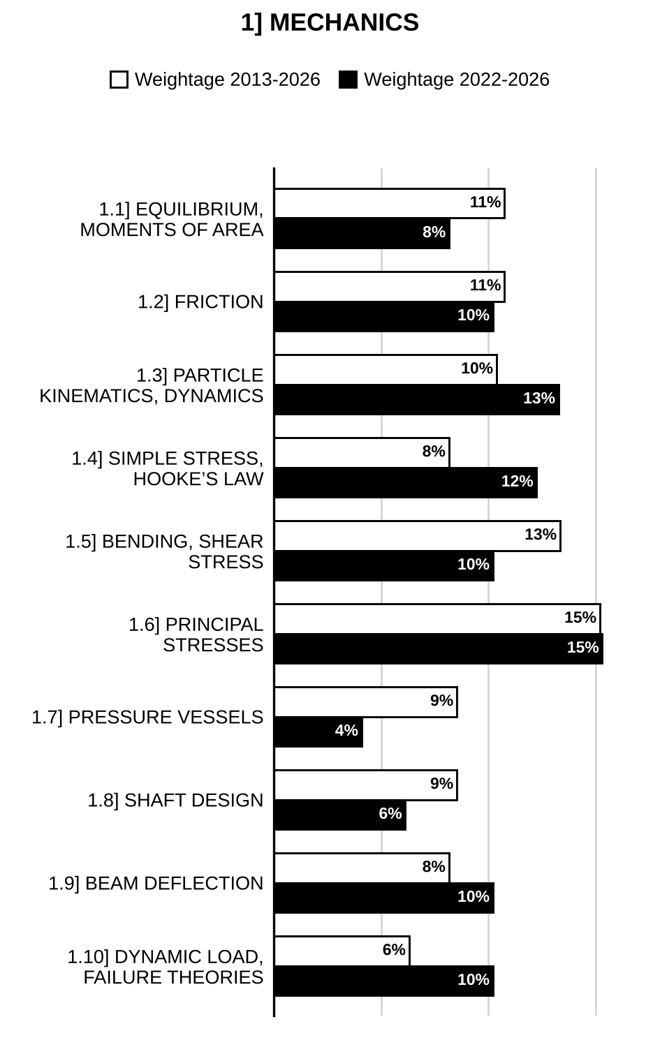
1.1] Equilibrium and moments of area
20 questions
A uniform beam has a mass of 50 kg per metre length. Compute the reactions at the support O. The force loads shown lie in a vertical plane.
[Figure: Bent cantilever beam OABC built in (fixed) at a wall at O on the left. Horizontal portion: O to A = 1.8 m, then A to the bend = 0.6 m; a 3 kN vertical downward load acts at A. From the bend the beam rises to the right as a straight inclined portion making 30° with the horizontal; along the inclined portion, bend to B = 0.6 m and B to C = 0.6 m (C is the free end). A couple of 4 kN-m (shown counterclockwise) acts at B. A force of 1.4 kN acts at C perpendicular to the inclined portion, directed downward to the right (towards the beam).] [2026/10m/1a]
A cylinder C weighing 1000 N is supported by two cylinders A and B weighing 500 N each as shown in the figure. Calculate the contact forces at P, Q and R.
[Figure: Two smaller cylinders A (left) and B (right), each with a diameter dimension (rim to rim through the centre) marked 1 m, rest on the horizontal floor of a rectangular channel with vertical side walls; the inside width of the channel is 3 m. Cylinder A touches the left wall at R and the floor at Q; cylinder B touches the right wall and the floor. A larger cylinder C, diameter dimension marked 2 m, rests on top of A and B; P is the contact point between C and A.] [2025/10m/2a(i)]
A heavy carriage wheel of weight W, and radius r is to be dragged over an obstacle of height h by a horizontal force P applied to the centre of the wheel. Show that P is slightly greater than . [2023/10m/1a]
A pipe with external forces is shown in Figure 1(c). The loads 300 N, 200 N, and 900 N are acting at the centres of pipe sections as shown in the figure. Find the resultant of force system at point A shown in the figure.
[Figure: Figure 1(c) – Bent pipe fixed to a vertical wall (the x-y plane) at point A, with axes x, y (vertically up) and z through A. From A the pipe runs 20 m along the z-axis, then bends and runs 8 m vertically downward (–y), then bends and runs 10 m parallel to the x-axis to its free end. Loads: 900 N acting vertically downward at the centre of the 20 m section; 200 N acting vertically downward (along the pipe) at the centre of the 8 m section; 300 N acting vertically downward at the centre of the 10 m section; at the free end: 500 N vertically downward, 600 N parallel to the z-axis (in the +z direction) and 400 N parallel to the x-axis (in the +x direction)] [2022/10m/1c]
What is the supporting force system at A for the cantilever beam shown in the figure? Neglect the weight of the beam.
[Figure: Horizontal cantilever beam AB, fixed into a wall at A (left end), total length 3 m. A triangular (linearly varying) distributed load acts downward on the first 1.5 m from A, increasing from zero at A to 400 N/m at 1.5 m from A. At 1.5 m from A a rigid bent bracket hangs below the beam, going down and then 0.5 m to the right, and carries a vertical downward load of 300 N at 2.0 m from A (dimensions 1.5 m, 0.5 m). The remaining 1 m extends to the free end B, where a force of 500 N acts downward to the right, inclined at 30° below the horizontal] [2021/10m/1a]
An inscribed circular hole is made in a triangular lamina with each side ‘a’. Find the area moment of inertia of this lamina about one of the sides. [2021/15m/4b]
A tower guy wire is anchored by means of a bolt at A. If the magnitude of the tension in the wire is 2500 N, determine the components of the force acting on the bolt in the x, y and z directions.
[Figure: Tower with its base at the origin O; y-axis vertical along the tower, x-axis horizontal to the right, z-axis horizontal towards the viewer. Top of tower B is 80 m above the base (on the y-axis). Guy wire runs from B down to the anchor bolt A on the ground, A being 40 m from the base measured parallel to the x-axis and 30 m measured parallel to the z-axis on the side away from the viewer (the 40 m dimension is drawn between two lines parallel to the z-axis, one through the base and one through A; the 30 m dimension runs from the x-axis back to A, i.e. in the negative z direction), so A = (40 m, 0, –30 m) and B = (0, 80 m, 0)] [2020/10m/1b]
Determine the moment of inertia of the shaded area with respect to the x-axis.
[Figure: Shaded rectangle 240 mm wide and 120 mm high with its bottom-left corner at the origin; the x-axis runs along the bottom edge and the y-axis along the left edge. A semicircle of radius r = 90 mm, centred at the mid-point of the top edge (120 mm from the y-axis), is cut out from the top edge downwards] [2020/10m/2c]
A 600 N cylinder is supported by the frame BCD as shown in the Figure 1(a). The frame is hinged at D. Determine the reactions at A, B, C and D.
[Figure 1(a): Vertical wall (hatched) on the right. Frame BCD: a horizontal top member from the hinge D on the wall extends 300 mm to the left, a vertical member runs down 600 mm, and a short horizontal bottom member returns to the right under the cylinder. Cylinder of radius r = 150 mm, centre O, rests on the bottom member (contact B, directly below O), touches the vertical member of the frame at C (left) and the wall at A (right), C, O and A lying on one horizontal line] [2019/10m/1a]
A cord ACB, 5 m long is attached at points A and B to the vertical walls, 3 m apart (Figure 1). A pulley of negligible radius carries a suspended load of 200 N and is free to roll without friction along the cord. Determine the position of equilibrium as defined by the distance X, that the pulley will assume and also the tensile force in the cord.
[Figure: Figure 1 – Two vertical walls 3 m apart. Cord end A is attached to the left wall and end B to the right wall, B being 1 m higher than the level of A (horizontal dashed line A–H–I through A meets the right wall at I; BI = 1 m). The pulley C hangs on the cord with a 200 N load suspended from it; X is the horizontal distance of C from the left wall. Both cord segments CA and CB carry tension T and make equal angles θ with the horizontal dashed line F–C–G through C (F on the left wall, G on the right wall); segment BC, extended as a dashed line, meets the left wall at D, where it also makes angle θ with the horizontal dashed line D–E; H is the point where BC crosses the dashed level A–I of A; a vertical dashed line through C marks X. A rectangle closes the bottom of the walls below D–E.] [2018/10m/1a]
A beam AB of length 2 m, hinged at A and supported at B by a cord which passes over two frictionless pulleys (P, Q), carries a 50 kN load as shown in Fig. 1(a). Determine the distance x, where 100 kN load is located on the beam, if the beam is to remain in equilibrium in horizontal position. Also determine the reaction at the hinged end.
[Figure: Fig. 1(a) – Horizontal beam AB, 2 m long, hinged to a wall at A; a 100 kN vertical downward load acts on the beam at distance x from A. A cord tied to end B runs vertically up and over a fixed pulley P hanging from the ceiling at C, then down and round under a movable pulley Q, and up again to a fixed point D on the ceiling; the 50 kN load hangs from pulley Q. Tension T is marked in every segment of the cord (B to P, P to Q, Q to D).] [2017/10m/1a]
Find the moment of inertia of the shaded area shown in the figure, about the edge AB.
[Figure: Rectangle ABCD with A bottom-left, B bottom-right, C top-left, D top-right; AB = 10 cm (width), height BD = 20 cm; a semi-circle of radius R = 5 cm is cut out from the top edge CD (its diameter lying along CD, bulging downwards into the rectangle); the remaining area is shaded (hatched)] [2016/10m/1a]
Find the centroid of the element shown in Figure 2(c).
[Figure: Figure 2(c) – Plane lamina: a rectangle 200 mm wide and 140 mm high from which a rectangular notch 40 mm wide is cut at the top-right corner, the remaining right edge being 80 mm high (i.e. the notch is 40 mm × 60 mm, shown by dashed lines); a circular hole, marked 100 mm across its diameter, has its centre 100 mm from the left edge and 70 mm above the bottom edge] [2015/10m/2c]
In the Figure shown, a plate is supported at three positions, A, B and C. A is the ball and socket support, B is the roller support and CD is the cord. Determine the components of reactions at A and B and tension in cord CD.
[Figure: Horizontal triangular plate ABC in the x–y plane with C at the origin; B on the x-axis 4 m from C (marked 2 m + 2 m) and A on the y-axis 3 m from C (marked 2 m + 1 m). A vertical load of 400 N acts downward on edge CB at 2 m from C (2 m from B); a vertical load of 300 N acts downward on edge CA at 2 m from C (1 m from A). Cord CD runs vertically upward along the z-axis from corner C to a fixed support D. Supports at A and B as stated in the text.] [2013/10m/1b]
A cylinder having mass 40 kg is hung by means of cables and which are attached to the top of the vertical wall. The distance of points and on the wall from a line along the wall parallel to the axis of cylinder are 8 m and 10 m respectively. A horizontal force along the line perpendicular to the wall has been applied at the cylinder which pulls it by a distance 1.2 m away from the wall. The point is on the cylinder and it is 10 m below . Determine tension in each cable and the force applied at the cylinder. [2012/20m/2b]
Compute second moment of area of the plane lamina shown in the above figure about an axis parallel to the base and passing through the centroid.
[Figure: Plane lamina (printed above the text of 3(a)) – a rectangle 22 cm high standing on the base, topped by a semicircle of radius 8 cm whose diameter is the top edge of the rectangle (so the rectangle is 16 cm wide); attached to the right side of the rectangle is a right-angled triangle whose vertical side is the 22 cm right edge of the rectangle (shown dashed) and whose base lies along the common base line; overall base length = 25 cm (so the triangle base is 9 cm), the hypotenuse running from the top-right corner of the rectangle down to the right end of the base] [2012/20m/3a]
The crane shown in Figure above is supported by cables BD and BE. The distances marked are in m. What are the tensions in the cables BC, BD and BE, when BC is parallel to the x-axis?
[Figure: Space crane with axes x (horizontal, to the right), y (vertical) and z (horizontal, towards the viewer) through A. Vertical mast AB of height 12 standing on a ball and socket joint at A (origin). A boom runs from A up to point C, from which a load of 50 kN hangs; cable BC runs from the top of the mast B to C, parallel to the x-axis, and the horizontal distance of C from the mast along x is 12. Cables BD and BE run from B down to ground anchors D and E. D and E lie on a dashed ground line parallel to the z-axis, which meets the negative x-axis (through A) at right angles at a point 10 from A; D is 8 from that point on one side and E is 8 on the other side. All distances in m.] [2010/8m/1e(ii)]
Define a general case of forces acting on a rigid body. State clearly and precisely the equations of equilibrium for this body. How do these equations change when applied to a particle? [2009/8m/1a(i)]
A smooth hollow cylinder of radius r open at both ends rests on a smooth horizontal plane. Two smooth spheres of weights and , and radii and respectively are placed inside the cylinder, with the larger sphere (radius ) resting on the horizontal plane as shown in Fig. 1. Determine the minimum weight W of the cylinder that will prevent the cylinder from tipping over.
[Figure: Fig. 1 – Vertical hollow cylinder (walls hatched, wall thickness t marked at the bottom right) standing on a hatched horizontal plane; inside width between the walls marked 2r. The larger sphere (radius , weight acting downward at its centre) rests on the horizontal plane touching the right wall; the smaller sphere (radius , weight acting downward at its centre) rests on top of the larger sphere, to its left, touching the left wall. Label “Hollow Cylinder” with arrow to the right wall.] [2009/12m/1a(ii)]
A homogeneous ball of weight Q and radius a as well as a weight P are suspended by cords from a point O as shown in Fig. 5. The distance OM is b. Find the inclination of OM with the vertical when the system is in equilibrium.
[Figure: Fig. 5 – Ball of radius a with centre M hangs from point O by a cord OM of length b inclined at angle to the vertical through O. A second cord from O passes down over the right side of the ball (in contact with its surface) and hangs vertically, carrying the weight P below the ball.] [2009/8m/3a(i)]
1.2] Friction
10 questions
Determine the magnitude P of the horizontal force required to initiate motion of the block of mass for the cases: (A) P is applied to the right, and (B) P is applied to the left. Compute a general solution in each case, and then evaluate your expression for the values , kg, , and .
[Figure: Block of mass resting on a horizontal floor (coefficient between block and floor). A uniform bar of mass m rests with its lower end A on the top of the block (coefficient at the contact A) and its upper end B pinned to a vertical wall on the right; the bar makes angle with the horizontal at A. Force P(B) is shown as a solid horizontal arrow acting on the left face of the block, pointing to the right; force P(A) is shown as a dashed horizontal arrow at the right face of the block, pointing to the left.] [2026/10m/4c]
A gripper is shown in the figure. A horizontal force N is applied to the handle of the lever at E. The mean diameter of the single square threaded screw at C and E is 25 mm and lead is 5 mm. Determine the clamping force developed at G. The coefficient of static friction is .
[Figure: Gripper (clamp) with an upper and a lower horizontal jaw; the jaw tips at G (left end) grip a workpiece of two stacked blocks. A vertical link AB is pinned to the upper jaw at A and to the lower jaw at B, at a horizontal distance of 200 mm from G. A vertical single square threaded screw passes through the upper jaw at C and the lower jaw at D, 200 mm to the right of AB. Below D the screw ends in a T-handle; the force is applied at E on the handle, at 125 mm from the screw axis.] [2025/10m/1a]
A rod of length 2 m and weight 450 N rests on ground at one end. The other end is supported by a cord through which a force of 200 N is applied. What is the minimum angle for which equilibrium is possible? The coefficient of static friction between the rod and the floor is 0.4:
[Figure: Uniform rod, 2 m long, with its lower end resting on the rough horizontal floor () and inclined at angle to the floor; its weight 450 N acts downwards at the midpoint (1 m from each end, lengths marked 1 m and 1 m). A cord attached to the upper end runs up and to the left at angle to the horizontal, passes over a small fixed pulley (mounted on a short post standing on a fixed base) and leaves the top of the pulley horizontally to the left, where a pull of 200 N is applied] [2024/10m/1a]
The coefficient of friction for all contacting surfaces in Figure 3(a) is 0.2. Does the 25 kg force move the block A up, hold it in equilibrium, or is it too small to prevent A from coming down and B from moving out? The 25 kg force is exerted at the mid-plane of the block so that we can consider this a coplanar problem.
[Figure: Figure 3(a) – Block A (100 kg), 0.6 m wide, rests with its left vertical face against a fixed vertical wall; its lower face is inclined at 15° to the horizontal (rising to the right) and rests on the sloping upper face of wedge B (50 kg). Wedge B lies on the horizontal floor, its horizontal base being 0.6 m long, with its vertical right face at the higher end of the slope; a horizontal force of 25 kg acts on the right face of B, pushing it to the left (towards the wall). A separate sketch indicates the 15° slope angle] [2023/20m/3a]
What is the value of P in the system as shown in Figure 2(b) to cause the motion to impend? Assume the pulley smooth and coefficient of friction, between the other contact surfaces.
[Figure 2(b): Block B (500 N) rests on a horizontal surface; force P is applied at its centre at 30° above the horizontal, pulling away (up and to the right). A string from block B runs horizontally to the left over a smooth pulley at the top corner of an inclined plane and then down parallel to the incline to block A (750 N), which rests on the incline; the incline makes 60° with the horizontal ground] [2019/15m/2b]
A block weighing 500 N just starts moving down a rough inclined plane when it is subjected to 200 N force acting up and parallel to the inclined plane and it is moving up the plane when pulled by a force of 300 N parallel to and up the plane. Find the inclination of the plane and the coefficient of friction between the inclined plane and the block. [2018/20m/2a]
Fig. 2(c) shows three flat blocks positioned on the 30° incline. A force P parallel to the incline is applied to the middle block. The movement of the upper block is prevented by attaching to a fixed support by a wire. The coefficient of static friction for each of the three pairs of mating surfaces is shown in the figure. Determine the maximum value which P may have before any slipping takes place.
[Figure: Fig. 2(c) – Incline at 30° to the horizontal carrying three stacked flat blocks: bottom block 35 kg on the incline, middle block 45 kg, upper block 25 kg. The upper block is tied by a wire, parallel to the incline, to a fixed support at the top of the incline. Force P, parallel to the incline and directed down the incline, is applied to the lower end of the middle block. Coefficients of static friction: between the 25 kg and 45 kg blocks, between the 45 kg and 35 kg blocks, between the 35 kg block and the incline.] [2017/20m/2c]
An effort of 250 N is required just to move a certain body up an inclined plane of angle 20°, the force acting parallel to the plane. If the angle of inclination of the plane is made 25°, the effort, required again, applied parallel to the plane, is found to be 280 N. Find the weight of the body and coefficient of friction. [2016/10m/1c]
An automobile with the distance between front and rear wheels 3.0 m and height of centre of gravity 300 mm is travelling over a roadway inclined at an angle with horizontal. The coefficient of static and dynamic friction are 0.6 and 0.5 respectively. The automobile is a rear wheel drive and has a load of 18 kN. What is the maximum inclination that the automobile can climb at uniform speed? [2015/20m/4a]
In the Figure shown below, block C has a mass of 50 kg and is confined between two walls by smooth rollers. If the block rests on the top of the 40 kg spool, determine the required coefficient of static friction at A and B so that the spool slips at A and B when the magnitude of applied force P is increased to 300 N.
[Figure: Block C (50 kg) held between two vertical walls by smooth rollers on both sides; it rests on top of a spool (40 kg) at point A (top of the spool’s outer rim). The spool, centre O, rests on the horizontal ground at B (bottom of the outer rim). Outer radius OE = 0.4 m, inner hub radius OD = 0.2 m. A cord wound on the inner hub leaves from the bottom of the hub horizontally to the right and carries the applied force P.] [2013/10m/1a]
1.3] Kinematics and dynamics of particles
22 questions
The acceleration of a particle along a straight line is defined by , where t is in seconds. At , m and m/s. When s, determine: (I) The particle’s position, (II) The total distance travelled, and (III) The velocity of the particle. [2026/10m/3a(i)]
A car is moving in a straight line with a velocity of m/s for a short duration, where t is in seconds. Take initial time , . Find: (i) distance travelled in 4 s, and (ii) acceleration at 4 s. [2025/10m/4a]
Bodies , and of weights 100 N, 200 N and 150 N, respectively are connected as shown. If released from rest, what would be their respective velocities after 1 s? The pulleys are massless:
[Figure: Two fixed pulleys hang side by side from a ceiling. Body hangs from the rope on the left side of the left fixed pulley; the rope passes over the left fixed pulley, down and under a movable pulley from which body hangs, up and over the right fixed pulley, then down to a small guide pulley fixed (by a bracket to an inclined support) at the top of a plane inclined at 30° to the horizontal, and then down along the incline to body , which rests on the inclined plane on rollers] [2024/20m/2a]
From a balloon ascending with a velocity of 25 m/s above the surface of a lake, a stone is let fall and the sound of the splash is heard 5 seconds later. Find the height of the balloon when the stone was dropped, assuming that the velocity of sound is 340 m/s. [2023/10m/1c]
An automobile weighing 15 kN is moving at a speed of 100 km per hour. The dynamic coefficient of friction between the rubber tyre and concrete road is 0.60. When the driver jams on his brakes, the car goes into skid in the direction of motion. What is the distance the car will move before it comes to rest when (i) the road is flat, (ii) the road is 7° upward inclination, (iii) the road is 7° downward inclination? [2022/15m/4a]
The velocity of a particle, moving in the x-y plane is given by m/s at time t = 3.65 s. Its average acceleration, during the next 0.02 s is . Determine the velocity v of the particle at t = 3.67 s, and the angle between the acceleration vector and the velocity vector at t = 3.67 s. [2021/10m/1b]
A car starts from rest with an acceleration of 6 m/s which decreases linearly with time to zero in 10 seconds after which the car continues at a constant speed. Determine the time required for the car to travel 400 m from start. [2020/10m/1a]
A pressure tank issues water at A with a horizontal velocity u as shown in Figure 4. For what range of values of u, will the water enter the opening BC?
[Figure: Figure 4 – A tank of water standing on the ground discharges a horizontal jet at A (at ground level at the right-hand corner of the tank) with velocity u. A vertical wall stands at a horizontal distance of 3 m from A. The wall has an opening BC: the upper edge B is 1 m below the level of A and the lower edge C is a further 1.5 m below B. The jet trajectory (dashed parabola) is shown from A towards B.] [2018/10m/4b]
The equation of motion of a particle is given, acceleration ‘a’ in terms of time ‘t’ as below: in which acceleration ‘a’ is in and time ‘t’ is in seconds. It is observed that the velocity of the particle is 10 m/s after 4 seconds; and the displacement of the particle is 6 m after 3 seconds. Determine: (i) Velocity after 6 seconds (ii) Displacement after 5 seconds. [2016/10m/2a]
A particle of mass m is resting at point B on a smooth semicircular cylinder of radius r, tied to a point A vertically above the centre of the cylinder at a height of 2 r, with a string of length 1.1 r as shown in Fig. 1(a). If the string is cut, find the angle defining the position C of the particle where it jumps off the cylinder.
[Figure: Fig. 1(a) – Smooth semicircular cylinder of radius r resting on a horizontal (hatched) ground, centre O on the ground line. Point A lies vertically above O at height 2 r; the vertical line OA is marked r (from O up to the top of the cylinder) and r (from the top of the cylinder up to A). A string of length 1.1 r runs from A to the particle at point B on the cylinder surface; OB makes angle with the vertical. Point C on the surface further along the same side; OC makes angle with the vertical.] [2014/10m/1a]
A compound pendulum of mass 27 kg is suspended from a pivot, such that the distance of pivot from the mass centre of pendulum is 380 mm. When the pendulum swings about its pivot with small oscillation, the period of oscillation is 1.60 second. If the pendulum is now made to swing with amplitude of 45° on each side of the vertical, find the force exerted on the pivot at the extremity of the swing. [2013/25m/2a]
A stuntman drives a motorcycle around a circular vertical wall 30 m in diameter. The coefficient of friction between the tyre and wall is 0.6. Determine the minimum speed that will prevent sliding down the wall. Determine the angle also by which the motorcycle is inclined to the horizontal. [2012/12m/1b]
A particle has initial velocity of 30 m/s towards the right at 30° with the horizontal. The retardation along horizontal axis is and along upward vertical axis is . Determine the horizontal distance covered until the particle reached a point 30 m below its original elevation. [2012/10m/4c]
An elevator starts from rest and raises vertically 40 m to attain its maximum velocity in T seconds, with acceleration record shown in the figure. Determine the time T and the maximum velocity reached by the elevator.
[Figure: Acceleration–time record: vertical axis a, horizontal axis time; the acceleration rises linearly from zero at t = 0 to a peak of 0.6 at t = T/3 (dashed lines mark the peak value on the a-axis and the time T/3), then decreases linearly to zero at t = T] [2011/10m/1a]
A model rocket of mass 0.1 kg is launched vertically from rest at time t = 0, with a constant thrust of 10 N for one second and no thrust for t > 1 second. Neglecting the air resistance and decrease in the mass of the rocket determine (i) maximum height reached by the rocket, (ii) time required to reach maximum height. [2011/15m/2a]
An automobile of mass 1225 kg starts from rest and travels a distance of 400 m. The co-efficient of static friction between tyre and road is 0.70, and air resistance is equivalent to , where D is in Newton and v is velocity in m/s. The automobile has front wheel drive and front wheel supports 62% of the total weight of vehicle. Determine the maximum speed reached by the automobile after travelling 400 m distance. [2011/15m/2b]
A solid cylinder of mass m and radius r starts rolling down an inclined plane. What will be the velocity of its centre of mass after it has come down by 3 m vertically? (Assume ) [2010/4m/1e(i)]
Figure shows a polyspast lifting a weight Q equalling 1000 N by another weight of P equalling 300 N. Neglecting friction and the masses of the pulleys and cables and the inclinations of cables, determine the distance moved by Q in 2 seconds from start.
[Figure: Polyspast (block and tackle): an upper block hung from the ceiling carries a large pulley and, below it on the same strap, a smaller pulley; a lower movable block carries a smaller pulley above a large pulley, with the weight Q hanging from the bottom of the lower block. A single cable, its end fixed to a hook under the upper block, passes alternately round the pulleys of the lower and upper blocks (four cable runs supporting the lower block); its free end comes down from the left side of the upper large pulley and carries the weight P. A hatched vertical wall is drawn at the left.] [2010/18m/3a(i)]
Small steel balls fall from rest through the opening at A at a steady rate of two per second. Find the vertical separation h of two consecutive balls when the lower one has dropped 5 m from A.
[Figure: A row of steel balls on a horizontal (hatched) shelf rolls to an opening at A at the end of the shelf; balls fall vertically one below the other through A, and the vertical distance between two consecutive falling balls is marked h.] [2010/12m/3a(ii)]
A body A weighing descends down an inclined plane D which makes an angle with the horizontal and pulls a load B that weighs by means of a weightless and inextensible string passing over a pulley C as shown in Figure. Determine the horizontal component of the pressure with which the inclined plane D acts on the floor rib E.
[Figure: Wedge-shaped inclined plane D resting on the horizontal (hatched) floor, with a vertical face on the left and the inclined face rising from the right at angle to the horizontal. Pulley C is mounted at the top corner of the wedge. Body A lies on the inclined face; the string from A runs parallel to the incline over pulley C and hangs vertically down beside the vertical face, carrying load B. E marks the floor rib at the foot of the vertical face of the wedge.] [2010/20m/3b(i)]
A satellite is orbiting around the Earth at an altitude of 320 km. Assuming the Earth radius as 6500 km and both the orbit and the Earth as circular, determine the speed of the satellite. [2010/10m/3b(ii)]
A body A of weight 10 kN is connected to an another body B of weight 50 kN, resting on a smooth table of weight 200 kN through an inextensible thread, passing over a freely rotating pulley mounted on a corner of the table. Find the vertical component of the reaction of the ground on the table when the bodies A and B are in motion. Does the reaction change with time? The system is shown in Fig. 6.
[Figure: Fig. 6 – Table standing on the hatched ground; body B rests on the smooth horizontal table top; a horizontal thread from B runs over pulley C mounted at the right-hand top corner of the table and hangs vertically down beside the table, carrying body A.] [2009/12m/3a(ii)]
1.4] Simple stresses and Hooke’s law
21 questions
The fixed-ended bar ABCD consists of three prismatic segments, as shown in the figure. The end segments have a cross-sectional area and length mm. The middle segment has a cross-sectional area and length mm. Loads and are equal to 25.5 kN and 17.0 kN, respectively. (i) Determine the reactions and at the fixed supports. (ii) Determine the compressive axial force in the middle segment of the bar.
[Figure: Horizontal bar ABCD fixed between two walls at A (left) and D (right). Segment AB (area , length ), segment BC (larger area , length ), segment CD (area , length ). Axial load acts at B pointing to the right; axial load acts at C pointing to the left.] [2026/10m/1b]
The aluminium rod ABC having Young’s modulus 70 GPa consisting of two cylindrical portions AB and BC, is to be replaced with a cylindrical steel rod DE with Young’s modulus 200 GPa of same overall length. Determine minimum required diameter, d, of the steel rod if its vertical deformation is not to exceed the deformation of aluminium rod under the same load and if the allowable stress in the steel rod is not to exceed 165 MPa.
[Figure: Left: vertical stepped aluminium rod ABC standing on a fixed base at C, with an axial compressive load of 125 kN applied downward at the top A; upper portion AB is 300 mm long and 38 mm in diameter, lower portion BC is 450 mm long and 56 mm in diameter. Right: vertical steel rod DE of uniform diameter d standing on a fixed base at E, with 125 kN applied downward at the top D.] [2025/10m/1b]
Two thick washers are placed on the two ends of a copper tube and a steel bolt of pitch 1.8 mm is made to pass through these washers as shown in the figure below. The nut is tightened first with hand so that there are no stresses in the tube. Now, the nut is further tightened with the spanner through one-fourth of a turn. Calculate the axial stresses developed in the tube and the bolt. Young’s modulus values for steel and copper are 200 GPa and 105 GPa, respectively:
[Figure: Steel bolt, 12 mm dia, with hexagonal head at the left and nut at the right, passing through a copper tube of length 120 mm (between the two washers); copper tube inside diameter 14 mm and outside diameter 20 mm; a washer at each end of the tube between the tube and the bolt head / nut] [2024/10m/1c]
A rectangular plate with a central circular hole of diameter 250 mm is subjected to two mutually perpendicular direct stresses of magnitudes and along the and directions, respectively. In addition, a shear stress of magnitude acts on all the four planes on which the direct stresses act (see the figure below). The circular hole is deformed into the shape of an ellipse. If the value of Young’s modulus of the material is and Poisson’s ratio is 0.3, find the lengths of the major and minor axes:
[Figure: Rectangular plate with a central circular hole of diameter 250 mm; tensile stress on the left and right faces (x-direction), tensile stress on the top and bottom faces (y-direction); shear stress acting leftwards on the top face, rightwards on the bottom face, upwards on the left face and downwards on the right face] [2024/20m/3b]
In Figure 2(a), AB is a rigid bar, CE is a steel rod of 20 mm diameter and DF is a copper rod of 20 mm diameter. If the end A is hinged and a load of 30 kN acts at the free end B, find the stresses in the steel and copper rods and the reaction at A. Given: and
[Figure: Figure 2(a) – Horizontal rigid bar AB, hinged at the left end A; point C at 1 m from A, point D at 2 m from C (3 m from A), free end B at 1 m beyond D (4 m from A). A vertical steel rod CE, 1 m long, runs upwards from C to a fixed support E above the bar; a vertical copper rod DF, 1 m long, runs downwards from D to a fixed support F below the bar. A vertical load of 30 kN acts downwards at B] [2023/20m/2a]
A steel wire of 8 mm diameter and length 50 m is used to lift a weight of 2000 N at its lowest end. Calculate the total elongation of the wire, if the density of the steel is and . [2021/10m/1e]
In a tensile test on a steel tube, outside diameter of 18 mm and inside diameter of 12 mm, an axial load of 12 kN produces a stretch of mm, on a length of 50 mm and a lateral contraction of outer diameter of mm. Calculate all the four elastic constants. [2019/10m/1d]
Draw the stress-strain diagram for mild steel and describe the salient points of the curve. [2017/10m/4b]
A bar of steel is 50 mm in diameter and 600 mm long. A tensile load of 150 kN is found to stretch the bar by 0.23 mm. The same bar, when subjected to a torque of 1.4 kN-m is found to twist through 1°. Find the values of the four elastic constants. [2016/10m/1b]
A circular punch, 20 mm in diameter, is used to punch a hole through a steel plate 10 mm thick. If the force necessary to drive the punch is 250 kN, determine the maximum shearing stress developed in the plate. [2015/10m/1c]
A close coiled spring has coil diameter to wire diameter ratio of 6. The spring deflects 30 mm under a load of 500 N and the maximum shear stress is not to exceed 350 MPa. Find the diameter and length of wire required. Modulus of rigidity of wire material = 80 GPa. [2012/10m/3b(ii)]
A plate is riveted to a channel section in a structure as shown in Fig. 4. An eccentric load of 12.5 kN acts as shown on the plate. Determine the rivet diameter so that the maximum shear stress in any rivet is not to exceed 40 MPa. Diameter of the rivet should be chosen from preferred series. Preferred rivet diameters (in mm): 12, 14, 16, 18, 20, 22, 24, 27, 30, 33, 36, 39, 42, 48.
[Figure: Fig. 4 – A vertical channel (shown with dashed hidden edges) carries a horizontal rectangular plate riveted to it by four rivets at the corners of a rectangle: horizontal pitch 200 mm between the two rivet columns and vertical pitch 200 mm between the two rivet rows. The centroid of the rivet group (marked ⊗) is shown 100 mm above the lower rivet row and 100 mm from the right rivet column. The right rivet column is 50 mm from the right edge of the channel; the plate projects to the right, and a vertical downward load of 12.5 kN acts on the plate at 400 mm to the right of the channel edge.] [2009/40m/2b]
(i) Under which condition of the state of stress at a point in the two dimensions, the Mohr’s circle will be reduced to a point? (ii) How much change in volume would a 100 mm side cube of steel will have when it is kept at a depth of 2 km in sea water? Assume specific gravity of sea water equal to 1.02, modulus of elasticity equal to 2.08 GPa and Poisson’s ratio equal to 0.29. [2007/20m/1c]
A steel bolt of diameter 1.8 cm passes coaxially through a copper tube of inner diameter 2 cm and outer diameter 3 cm. The length of the tube is 50 cm. Washers are placed at both ends of the tube. The bolt has threads at one end having pitch equal to 0.24 cm. The nut is turned on the bolt through 45° against the washer to tighten the assembly. Determine the stress developed in the bolt and the tube. Assume the modulus of elasticity of steel to be and modulus of elasticity of copper is half that of steel. [2007/20m/3a]
A compound tube is made by shrinking a thin steel tube on a thin brass tube. The areas of cross-section of these tubes are and , while the Young’s moduli are and , respectively. Show that for any tensile load, the extension of the compound tube is equal to that of a single tube of the same length and total cross- sectional area, but having a Young’s modulus of [2005/20m/1b]
A steel rod of square cross-section is loaded as shown in the figure.
[Figure: Stepped bar of three segments, each 2 m long, fixed to a wall at its left end. Segment 1 (next to the wall): solid square section 25 mm side; a force of 100 kN acts at its right end, directed to the left (towards the wall). Segment 2: solid square section 20 mm side (same outer size as segment 3); a force of 75 kN acts at its right end, directed to the left. Segment 3: hollow square section, 20 mm × 20 mm outside with a 10 mm square hole (cross-section sketch shows a hollow square, 20 mm wide and 20 mm high); a force of 25 kN acts at the free right end, directed to the right (away from the wall). Lengths marked 2 m, 2 m, 2 m.]
Find the section which is subjected to maximum stress, its magnitude and nature. What will be total change in its length? Take E = 200 GPa. [2005/20m/1c]
(i) For a closed coil helical spring under compression illustrate the stress distribution across wire diameter. (ii) Differentiate between compound and composite helical springs. (iii) The spring load against which a valve is opened is provided by an inner helical spring arranged within and concentric with an outer helical spring. The free length of inner spring is 6 mm longer than the outer. The outer spring has 12 coils of mean diameter 25 mm, wire diameter 3 mm, and initial compression 5 mm when the valve is closed. Find the stiffness of the outer spring if the greatest force required to open the valve by 10 mm is 150 N. If the radial clearance between the springs is 1.6 mm, find the wire diameter of the inner spring if it has 10 coils. For both springs, . [2002/30m/3b]
A copper tube, 22 mm internal diameter, 30 mm outer diameter and 150 mm long is compressed by a nut tightening over a steel bolt, 20 mm diameter with 1 mm pitch. (i) If the nut is tightened by a quarter of a turn beyond the just touching position, determine the stress in the bolt. (ii) What would be the final stress in the bolt if the temperature of the assembly in (i) is to increase by 10 °C? Assume ; ; ; [1999/30m/4a]
A close coiled helical spring is of 80 mm mean coil diameter. The spring extends by 37.75 mm when loaded axially by a weight of 500 N. There is an angular rotation of 45° when this spring is subjected to an axial couple of magnitude 20.0 Nm. Determine the poisson’s ratio for the material of the spring. [1996/20m/2b]
A steel bracket is bolted to a column by three similar bolts as shown in the figure. It is subjected to an eccentric load of 30 kN as indicated. Determine a suitable minimum diameter for the bolts using a factor of safety of 5.0. Assume the bracket and the attached plate to be rigid. Take the allowable stresses for the bolt material in tension as and in shear as .
[Figure: (a) Front view of the bracket plate bolted to the column: two upper bolts, both marked D, on a horizontal line, at 154 [?] mm to the left and 160 [?] mm to the right of the vertical centre line; a third bolt E below them on the centre line. The 30 kN vertical load acts at 150 [?] mm from the centre line, in line with the right-hand bolt. (b) Side view: bracket bolted to the vertical column, the 30 kN downward load applied at 500 mm from the face of the column; the bracket tilts about its lower edge A at the column face; upper bolt force at 400 mm above A and lower bolt force at 100 mm above A] [1996/30m/3a]
The steel belt shown in figure given below has a thread pitch of 1.6 mm. If the nut is initially tightened up by hand so as to cause no stress in the copper spacing tube calculate the stress inducted in the tube and in the bolt if a spanner is then used to turn the nut through 90°. Take and as 100 GPa and 209 GPa respectively.
[Figure: A “10 mm dia steel bolt” passes through a copper spacer tube (“Copper space[r] 12 mm inside dia”) held between two end washers/plates by the bolt head and the nut; overall outside dimension of the assembly marked 18 mm; length of the tube between the plates marked “0 m” [?]] [1995/30m/4b]
1.5] Bending and shear stresses in beams
25 questions
A beam AB under loading is shown in the figure. The rigid bar DEF is welded at a point D. The Young’s modulus of the beam material is 200 GPa and its moment of inertia is . (i) Draw shear force diagram. (ii) Draw bending moment diagram. (iii) Find the maximum bending moment and its location. (iv) Find deflection at C.
[Figure: Horizontal beam AB, roller support at A (left) and pin support at B (right), carrying a uniformly distributed load of 750 N/m over its whole length. A rigid bar DEF is welded to the underside of the beam at D: it runs vertically down from D to E and then horizontally to the left from E to F; a vertical downward load of 700 N acts at F. Point C on the beam lies directly above F. Horizontal dimensions: A to C (line of the 700 N load) = 2.4 m, C to D = 0.9 m, D to B = 1.5 m.] [2025/20m/3b]
Show the loading on the beams corresponding to the bending moment diagrams shown below. The beams are simply supported at and :
[Figure: (i) Bending moment diagram of a simply supported beam of span 6 m (3 m + 3 m). At the B.M. is –1600 N-m; it varies linearly, crossing zero before mid-span, to +800 N-m at 3 m from ; over the right 3 m it falls from +800 N-m to zero at along a curve marked “Parabolic”]
[Figure: (ii) Bending moment diagram of a simply supported beam of span 3 m: B.M. of –1500 N-m at varying linearly to –2300 N-m at (negative throughout)] [2024/20m/3a]
A beam carries a uniformly distributed load of 360 N/m over the entire span together with a concentrated load of 400 N at the extreme left. The beam is having a span of 10 m and is supported at two points 7 m apart. The supports are so chosen, that each support carries half the total load. Draw the shear force and bending moment diagrams after obtaining the maximum bending moment and points of contraflexure. [2022/20m/3b]
Write the equations for shearing force and bending moment for various sections and draw SFD and BMD for the beam supported at A and B as shown in the figure.
[Figure: Horizontal beam A–C–D–B–E, simply supported at A (left end) and at B, with an overhang BE; AC = 2 m, CD = 2 m, DB = 2 m, BE = 1 m. A counterclockwise couple of 2 kN-m acts at C; a vertical downward load of 1 kN acts at D; a vertical downward load of 1 kN acts at the free end E; upward reaction arrows are shown at A and B] [2021/20m/2c]
Draw the shear force and bending moment diagrams for the beam and loading shown. Also determine the maximum values of shear force and bending moment along with their respective locations.
[Figure: Beam ABCDE with a pin (hinge) support at the left end A and a roller support at D; AB = 1.8 m, BC = 2.4 m, CD = 3 m, DE = 2.4 m (overhang DE). Point load 90 kN downwards at B, point load 54 kN downwards at C, uniformly distributed load 22 kN/m over the overhang DE] [2020/20m/3a]
For the single overhanging beam as shown in Figure 2(a), draw the Shearing Force and Bending Moment diagram, if . Also find the maximum Bending Moment and its location. Also locate the point of contraflexure.
[Figure 2(a): Beam ABC with a pin (hinge) support at A (reaction ) and a roller support at B (reaction ); AB = 2L m, overhang BC = L m. Uniformly distributed load q kN/m (u.d.l.) over the whole span AB; point load P, kN acting downwards at the free end C] [2019/20m/2a]
A simply supported beam of rectangular section is 200 mm wide and 300 mm deep. It supports a uniformly distributed load of 6 kN/m over an effective span of 4 m as shown in Fig. 2 (a). Calculate the magnitude and direction of the principal stresses at a point located at 0.50 m from the left support and 50 mm above the neutral axis.
[Figure: Fig. 2(a) – Beam AB of span 4 m, supported at A (left) and B (right), carrying a uniformly distributed load of 6 kN/m over the whole span.] [2017/15m/2a]
The S.F. diagram of a beam with overhangs is shown in the figure. Determine the loading on the beam and draw the B.M. diagram.
[Figure: Shear force diagram of a beam with overhangs; lengths from left: 3 m, 5 m, 2 m. Over the left 3 m the S.F. is constant at 1 kN negative (–); at the end of the 3 m it jumps up to +5 (kN), then decreases linearly over the 5 m length from +5 (+) through zero to –5 (–) at the end of the 5 m; it then jumps up to +2 and stays constant at +2 kN (+) over the right 2 m length. Labels: 1 kN and 1 at the two ends of the left negative block, 5 at the top of the jump, 5 at the bottom of the sloping line, 2 and 2 kN over the right positive block] [2016/20m/2b]
For the beam shown in Figure 2(b), write the equations for the shear force and bending moment at any point. Also draw the shear force and bending moment diagrams.
[Figure: Figure 2(b) – Horizontal beam with x-axis pointing to the right from its right end; total length 0.6096 m + 4.2672 m + 0.6096 m. A clockwise couple of 5423 Nm (curved arrow round the left end, rising from below the beam to an arrowhead at the top pointing right) acts at the left (free, overhanging) end; a pin (hinge) support is at 0.6096 m from the left end; a downward point load of 15568 N acts 4.2672 m to the right of the pin support, i.e. 0.6096 m from the right end; a roller support is at the right end] [2015/20m/2b]
The bending moment diagram for a simply supported beam AB is shown in Fig. below. Sketch the loading diagram and S.F. diagram of the beam.
[Figure: Bending moment diagram for simply supported beam AB of span 5 m: the moment varies linearly from zero at A to 12 kN.m (negative, marked “–”) at a section 2 m from B, where it jumps to 8 kN.m (positive, marked “+”) and then varies linearly to zero at B.] [2013/10m/1c]
A simply supported beam of 3 m span is subjected to loads as shown below. The beam is of I-section and all its dimensions are shown in mm. Determine the principal stresses at point D in the web. This section is located at a distance of 1 m from the right hand support of the beam.
[Figure: Simply supported beam AB of span 3 m, hinged at A and on rollers at B, carrying a uniformly distributed load of 2 kN/m over the whole span and a concentrated load of 4 kN at C, 1 m from B. I-section (dimensions in mm): overall depth 200, flanges 75 wide and 10 thick, web 15 thick; point D in the web at 50 above the neutral axis N–A.] [2013/25m/2b]
An I-beam with the following dimensions is subjected to a shearing force of 20 kN. Flange: breadth = 50 mm, thickness = 5.5 mm Web: depth = 109 mm, thickness = 3.5 mm Area of cross-section = M.I. = . Calculate the value of the transverse shear stress at the neutral axis – and at the top of the web. [2012/12m/1d]
Compare the flexural strengths of the following three beams of equal weight. 1. I-section 300 mm × 150 mm with flanges 20 mm thick and web 12 mm thick. 2. Rectangular section having depth twice the width. 3. Solid circular section. [2012/15m/4a(i)]
A beam ABCD is loaded as shown in Fig. given below. The beam is of rectangular section 50 mm × 100 mm. (i) Sketch the S.F. and B.M. diagram for the beam. (ii) Determine the maximum bending stress at section B of the beam.
[Figure: Horizontal beam ABCD, total length 11 m: A at the left end on a pin (hinged) support; B at 3 m from A; C at 6 m from A (3 m from B) on a roller support; D the free right end, 5 m beyond C (overhang). A triangularly distributed load acts over AC, increasing linearly from zero at A to 60 N/m at C; a couple of 5000 N.m is applied at B (curved arrow, anticlockwise as drawn); a downward arrow (concentrated load) is drawn at the free end D, with no magnitude marked] [2011/25m/3c]
A beam is of square section with diagonals 60 mm long, vertical and horizontal, as shown in Fig. 2. Shear force at a particular section is 5 kN. What is the shear stress at layer AB as shown?
[Figure: Fig. 2 – Square cross-section placed with its diagonals vertical and horizontal; overall height 60 mm (vertical diagonal) and overall width 60 mm (horizontal diagonal). Layer AB is a horizontal line across the upper half of the section (A on the upper-left side, B on the upper-right side), located 15 mm above the horizontal diagonal (neutral axis).] [2009/15m/1b(i)]
A beam ABCD, 6 m long, hinged at both ends A and D, is subjected to moments 6 kN-m (cw) at B and 3 kN-m (ccw) at C as shown in Fig. 3. Sketch the bending moment diagram of the beam. How many points of contraflexure are there in the beam?
[Figure: Fig. 3 – Horizontal beam ABCD with hinged supports at A and D; AB = 2 m, BC = 2 m, CD = 2 m. A clockwise couple of 6 kN-m is applied at B and a counter-clockwise couple of 3 kN-m at C.] [2009/5m/1b(ii)]
The section of a beam is square of 10 cm side with one diagonal vertical. It is subjected to a transverse shear force of magnitude F. Determine the problem of the layer at which the transverse shear stress is maximum. [2007/20m/3b]
Construct the bending moment and shearing force diagram for the beam as shown in the figure given below:
[Figure: Horizontal beam ABCDEFG. Point A is the left end; hinged (pin) support at B; roller support at E; G is the free right end (overhang EFG). Distances: AB = 0.5 m, BC = 1 m, CD = 2 m, DE = 1.5 m, EF = 0.5 m, FG = 0.5 m. Loads: uniformly distributed load 20 kN/m over AB; a clockwise couple of 100 kN-m applied at C; a downward point load of 50 kN at D; a downward point load of 40 kN at F.] [2006/20m/1c]
A beam ABCD, 10 m long is supported at B, 1 m from end A and at C, x m from end D. The beam carries a point load of 10 kN at end A and a uniformly distributed load of 4 kN per metre run throughout its length. Determine the value of x if the centre of the beam is the point of contraflexure. Draw the bending moment diagram.
[Figure (printed above the text): Overhanging beam ABCD. Point load 10 kN acting downwards at the left end A; uniformly distributed load 4 kN/m over the whole length A to D. Supports (upward reactions) at B, 1 m from A, and at C, distance x from the right end D.] [2004/30m/3a]
Draw Shear Force and Bending Moment diagrams for the beam ACDB shown in figure where two couples are acting. Find the ratio of deflections in the beam at locations C and D where the couples are acting.
[Figure: Horizontal beam ACDB, 3 m long, with a hinged (pin) support at the left end A and a roller support at the right end B. Points C and D divide it into three equal spans: AC = 1 m, CD = 1 m, DB = 1 m. A clockwise couple is applied at C and a clockwise couple is applied at D (each drawn as a curved arrow over the beam with the arrowhead on the right-hand side pointing down). No other loads.] [2002/30m/3a]
A beam ABCD, 8 m long, hinged at end A and roller supported at end D carries the transverse loads as shown in the above figure. Determine the support reactions and draw the BM diagram for the beam.
[Figure (printed above the text): Horizontal beam ABCD, 8 m long, with a hinge (pin) support at the left end A and a roller support at the right end D; AB = BC = 2 m, and D is 4 m beyond C (the dimension line shows 2 m, 2 m, 2 m, 2 m from A to D, the third division ending at a point 2 m to the right of C). A vertical downward load of 20 kN acts directly on the beam at B. At C a rigid bracket is fixed to the beam: a vertical post rises from the beam at C and turns horizontally to the right; a vertical downward load of 20 kN acts at the end of the bracket arm, which lies 2 m to the right of C (above the point 6 m from A), without touching the beam there.] [2001/30m/3b]
An I-beam has flanges 10 cm wide and 1 cm thick, and the web 12 cm high and 1 cm thick. At a section of this beam acts a bending moment of 1000 kg m and a shear force of 10,000 kg. Find the normal and shear stresses at the following points on the vertical centre line: (i) Top of flange (ii) In web at the junction with flange (iii) At the neutral axis. [1999/20m/1a]
A beam of flexural rigidity is simply supported over a span of 6 m as shown in the figure. It carries a concentrated load of 24 kN, 2 m from the left-hand support, and a UDL of 6 kN/m on the central 2 m part. The beam has vertical members welded onto it 2 m from the right-hand support which carry two horizontal loads of 24 kN as shown in the figure. The distance between these loads is 1 m. (i) Draw the Bending Moment Diagram for this beam. (ii) Calculate the vertical deflection of the central point of the beam.
[Figure: Horizontal beam, 6 m span, simply supported at both ends (upward reaction arrows at the left and right ends). Marked distances: 2 m from the left support to the first load point and 2 m from the vertical member to the right support. A downward concentrated load of 24 kN acts at 2 m from the left support; a uniformly distributed load of 6 kN/m acts on the central 2 m (from 2 m to 4 m from the left support). At the end of the UDL (4 m from the left support, 2 m from the right support) a rigid vertical member is welded to the beam, extending above and below it: at its upper end a horizontal load of 24 kN acts towards the right; at its lower end a horizontal load of 24 kN acts towards the left; the vertical distance between the lines of action of the two horizontal loads is 1 m.] [1999/30m/4b]
A horizontal beam of square cross-section is so placed that the loading in the transverse plane is along one of its diagonals of length d. If the shear force at a section of the beam is S, draw the shear stress distribution diagram for the section and indicate the position and magnitude of the maximum shear stress on it. [1998/30m/4b]
The Shear Force diagram for rectangular cross-section beam AB is shown in the figure given below. Width of the beam is 100 mm and depth is 250 mm. determine the maximum bending stress in the beam.
[Figure: SF diagram for beam AB divided into three segments of 1m, 1m and 1 [?] m. At A the shear force jumps to 15 kN (drawn below the base line) and stays constant over the first 1 m; at 1 m from A it steps up (reduces in magnitude) by an amount marked with a small dimension arrow whose value is illegible [?] and stays constant over the second 1 m; at 2 m from A it steps up again by a second illegible amount [?]; over the last 1 m it varies linearly to zero at B] [1995/30m/3b]

Preparing for Prelims too?
Our UPSC Prelims Topic-wise PYQ eBook covers every Prelims question with detailed explanations, so you can see exactly where UPSC asks from.
View the BookDownload Free Sample1.6] Principal stresses and strains
30 questions
A turbine shaft of diameter d is under a thrust load P and torque T (as shown in the figure). Calculate the largest permissible value of the load P if the allowable normal stress is not to exceed . Given: mm, kN.m, MPa.
[Figure: Solid circular shaft of diameter d drawn in perspective; axial compressive thrust P applied at each end (arrows pointing into the end faces along the axis) and equal and opposite torques T applied at the two ends (curved arrows about the axis).] [2026/10m/1e]
A pressurized steel tank is constructed with a helical weld that makes an angle with the longitudinal axis (as shown in the figure). The tank has radius m, wall thickness mm, and internal pressure MPa. Also, the steel has modulus of elasticity GPa and Poisson’s ratio . Determine the following quantities for the cylindrical part of the tank: (I) The circumferential and longitudinal stresses. (II) The maximum in-plane and out-of-plane shear stresses. (III) The circumferential and longitudinal strains.
[Figure: Horizontal cylindrical pressure tank with rounded ends; helical weld lines run around the cylindrical part, labelled “Helical weld”; the angle is marked between the weld line and a horizontal line parallel to the longitudinal axis.] [2026/10m/3a(ii)]
The surface of an airplane wing is subjected to plane stress with normal stresses and and shear stress , as shown in the figure. At a counterclockwise angle from the x-axis, the normal stress is 37 MPa tension, and at an angle , it is 12 MPa compression. If the stress equals 110 MPa tension, what are the stresses and ?
[Figure: Square plane-stress element with origin O and axes x (to the right) and y (upwards); MPa tensile on the right and left faces (arrows pointing outward), tensile on the top and bottom faces (arrows pointing outward), and shear stress shown acting to the right on the top face, upward on the right face, to the left on the bottom face and downward on the left face.] [2026/10m/3b(i)]
A tank shown in the figure is filled with compressed air under pressure of 8 MPa. A torque of magnitude kNm is applied at the end. The tank has an inner diameter of 180 mm and thickness of wall 12 mm. Determine the maximum normal stress and maximum shearing stress in the tank considering the cylinder is thin.
[Figure: Vertical closed cylindrical tank fixed to a base plate at its bottom end; a torque T (curved arrow) is applied about the cylinder axis at the top end.] [2025/10m/1c]
A rectangular plate with a central circular hole of diameter 250 mm is subjected to two mutually perpendicular direct stresses of magnitudes and along the and directions, respectively. In addition, a shear stress of magnitude acts on all the four planes on which the direct stresses act (see the figure below). The circular hole is deformed into the shape of an ellipse. If the value of Young’s modulus of the material is and Poisson’s ratio is 0.3, find the lengths of the major and minor axes:
[Figure: Rectangular plate with a central circular hole of diameter 250 mm; tensile stress on the left and right faces (x-direction), tensile stress on the top and bottom faces (y-direction); shear stress acting leftwards on the top face, rightwards on the bottom face, upwards on the left face and downwards on the right face] [2024/20m/3b]
A plane stress condition exists at a point in a loaded structure. The stresses have the magnitude and directions shown on the stress element of Figure 3(b). Calculate the stress acting on the planes obtained by rotating the element clockwise through an angle of 15°.
[Figure: Figure 3(b) – Square stress element: normal stress on the left and right faces with arrows pointing into the faces (compressive); normal stress on the top and bottom faces with arrows pointing away from the faces (tensile); shear stress acting leftwards on the top face, rightwards on the bottom face, upwards on the left face and downwards on the right face] [2023/20m/3b]
A 20 mm diameter shaft is subjected to a torque of 80 Nm and a downward bending moment of 100 Nm at the centre. Draw the state of stress on the bottom surface of the shaft at the centre and find principal stresses and shear stress at the centre of the bottom surface. What is the angle of shear plane? [2022/15m/2a]
At a certain point in a piece of elastic material, there are normal tensile stresses of magnitude 120 MN/m, 60 MN/m acting orthogonally to each other. In addition, there is a shearing stress of 80 MN/m acting normal to the normal stresses. Determine: (i) the magnitude and direction of the principal stresses (ii) the magnitude and direction of the maximum shearing stress (iii) the normal and shearing stress on a plane inclined at 30° to the direction of 120 MN/m stress.
[Figure: Square element with tensile on the left and right faces (arrows pointing outwards), tensile on the top and bottom faces (arrows pointing outwards) and shear stress shown on all four faces: towards the left on the top face, towards the right on the bottom face, downwards on the right face and upwards on the left face] [2020/20m/2a]
Find the complementary shear stress for the element with stresses as shown in Figure 1(b) given below. The major principal stress is 120 MPa. What is the magnitude of maximum shear stress and minimum principal stress? Also, locate the principal planes and maximum shear stress planes.
[Figure 1(b): Square element with compressive normal stress 80 MPa on the left and right faces (arrows pointing into the faces), compressive normal stress 120 MPa on the top and bottom faces (arrows pointing into the faces); shear stress (magnitude not given) acting to the right on the top face, to the left on the bottom face, upwards on the right face and downwards on the left face] [2019/10m/1b]
An element with stresses acting on it at a point is shown in Figure 2. , , Determine: (i) Normal and shear stresses acting on a plane AB, whose normal is at an angle of 110° w.r.t. X-axis (ii) Principal stresses and their location (iii) Maximum shear stress and its location.
[Figure: Figure 2 – Square element with X-axis horizontal and Y-axis vertical. Normal stress 80 (tensile, arrows pointing outward on the left and right faces); normal stress 100 (compressive, arrows pointing into the top and bottom faces). Shear stress 50: on the top face acting to the left, on the bottom face acting to the right, on the right face acting downward, on the left face acting upward. Plane AB passes through the centre inclined at 20° to the X-axis (rising to the right); its normal (dashed line labelled “Normal”, with ) is at 110° from the X-axis; shear stress τ marked on the plane. All stresses in MPa.] [2018/10m/1b]
A state of plane stress is shown in Fig. 1(b). Determine the following: (i) Principal stresses (ii) Principal planes (iii) Maximum shear stress.
[Figure: Fig. 1(b) – Square element: 50 MPa tensile normal stress on the left and right faces (arrows pointing outward); 10 MPa compressive normal stress on the top and bottom faces (arrows pointing into the element); shear stress 40 MPa acting to the right on the top face, upward on the right face, to the left on the bottom face and downward on the left face.] [2017/10m/1b]
A simply supported beam of rectangular section is 200 mm wide and 300 mm deep. It supports a uniformly distributed load of 6 kN/m over an effective span of 4 m as shown in Fig. 2 (a). Calculate the magnitude and direction of the principal stresses at a point located at 0.50 m from the left support and 50 mm above the neutral axis.
[Figure: Fig. 2(a) – Beam AB of span 4 m, supported at A (left) and B (right), carrying a uniformly distributed load of 6 kN/m over the whole span.] [2017/15m/2a]
At a point in a material, the stresses on two mutually perpendicular planes are (tensile) and (tensile). The shear stress across these planes is . Find the magnitude and direction of the resultant stress on a plane making an angle of 40° with the plane of the first stress. Also find the normal and tangential stresses on this plane. [2016/10m/3a]
Consider a hollow circular shaft whose outside diameter is 0.0762 m and whose inside diameter is equal to one-half the outside diameter. The shaft is subjected to twisting moment of 2259.584 N-m as well as bending moment of 3389.376 N-m. Determine the principal stresses. Also determine the maximum shear stress. [2015/20m/2a]
Stresses at a point are shown in Fig. 1(b). What is the shear stress on plane AC, if on plane BC is 40 MPa? What is the magnitude of angle if AB is a principal plane? What is the maximum shear stress at the point?
[Figure: Fig. 1(b) – Right-angled triangular element ABC with the right angle at C: BC horizontal (bottom), AC vertical (right side), AB the inclined hypotenuse making angle with BC at B. A normal compressive stress of 60 MPa acts on face AC (arrow pointing into the face from the right); a normal stress of 100 MPa acts on face BC (arrow pointing downward, away from the face) together with a shear stress along BC (arrow pointing towards C).] [2014/10m/1b]
A simply supported beam of 3 m span is subjected to loads as shown below. The beam is of I-section and all its dimensions are shown in mm. Determine the principal stresses at point D in the web. This section is located at a distance of 1 m from the right hand support of the beam.
[Figure: Simply supported beam AB of span 3 m, hinged at A and on rollers at B, carrying a uniformly distributed load of 2 kN/m over the whole span and a concentrated load of 4 kN at C, 1 m from B. I-section (dimensions in mm): overall depth 200, flanges 75 wide and 10 thick, web 15 thick; point D in the web at 50 above the neutral axis N–A.] [2013/25m/2b]
In a loaded component principal stresses at a point are 130 MPa and 30 MPa. Using Mohr’s stress circle, determine the state of stress at the point with respect to axes x′ and y′ which are inclined to and (principal stress) axes at 30° each in anticlockwise direction. Also determine principal strains at the point. Take E = 200 GPa and G = 80 GPa. [2013/20m/3a]
A cast iron sample when tested in compression fails along approximately 45° plane from its axis while when tested in torsion also fails along a 45° (approx.) helical plane from its axis. Explain the reason for such failure and mention about the dominating stresses causing failure. [2011/10m/1e]
A 1 m × 1 m mild steel sheet of 1 mm thickness is stretched in its own plane by stresses and as shown in figure below. Point O is centre of the plate. OC and OD are two mutually perpendicular lines inclined at 45° each to x and y directions respectively before application of stress. Determine the change in angle (in degrees) between OC and OD after application of stresses. Take modulus of rigidity of plate material G = 80 GPa.
[Figure: Square plate with centre O, under tensile (arrows outward on the left and right edges, labelled on the left and = 20 MPa on the right) and tensile (arrows outward on the top and bottom edges, labelled at the top and = 30 MPa at the bottom); from O, line OC runs up to the right at 45° to the horizontal (dashed horizontal reference through O) and line OD runs up to the left at 45° to the vertical (dashed vertical reference through O); small x–y axes (x to the right, y upward) are drawn near the top right corner] [2011/20m/4a]
The state of stress at a given point in a loaded component is given by , and and the principal stresses at the point are and . If the new axes at the point are changed to x′ and y′ such that state of stress w.r.t. the new axes are , and .
(i) Show that: [2010/6m/1a(i)]
(ii) Sketch the Mohr’s stress circle for pure shear stress state and hydrostatic state of stress. [2010/3m/1a(ii)]
(iii) A cast iron bar of 30 mm diameter and 1 m length is subjected to equal and opposite torque T applied at its ends. If tensile strength of cast iron is 80 MPa, what is the maximum value of torque T? Show the plane of failure for the applied sense of torque T. [2010/3m/1a(iii)]
Stresses on two perpendicular planes, at a point, are given in Fig. 7. What are the directions of principal planes with respect to plane BC? What are the principal strains on principal planes, if , ?
[Figure: Fig. 7 – Right-angled triangular element ABC with the right angle at C: BC horizontal (bottom face), AC vertical (right face), AB the inclined face making angle with BC at B. On face AC: normal stress 100 MPa (arrow pointing to the right, away from the face) and shear stress 20 MPa (arrow pointing downward). On face BC: normal stress 100 MPa (arrow pointing downward, away from the face) and shear stress 20 MPa (arrow pointing to the right).] [2009/20m/3b]
(i) Under which condition of the state of stress at a point in the two dimensions, the Mohr’s circle will be reduced to a point? (ii) How much change in volume would a 100 mm side cube of steel will have when it is kept at a depth of 2 km in sea water? Assume specific gravity of sea water equal to 1.02, modulus of elasticity equal to 2.08 GPa and Poisson’s ratio equal to 0.29. [2007/20m/1c]
A circle of 100 mm diameter is inscribed on a steel plate before it is stressed. Then the plate is loaded so as to produce stresses as shown in the above figure and the circle is deformed into an ellipse. Determine the lengths of major and minor axes of the ellipse and their directions. Take modulus of elasticity of steel as 2.1 and Poisson’s ratio 0.28.
[Figure (printed above the text): Rectangular plate with a circle drawn at its centre (centre lines shown). Normal stress 12 tensile on the top and bottom faces (arrow up on the top face, arrow down on the bottom face). Normal stress 6 compressive on the left and right faces (arrows pointing into the plate). Shear stress 4 : on the top face directed to the left, on the bottom face directed to the right, on the left face directed upwards and on the right face directed downwards.] [2004/20m/1b]
At a point in a material under stress, the intensity of the resultant stress on a certain plane is 50 (tensile) inclined at 30° to the normal of that plane. (Refer fig. 2) The stress on a plane at right angles to this plane has a normal tensile component of intensity of 30 . Find (i) The resultant stress on the second plane (ii) The principal planes and stresses (iii) Maximum shear stress and the plane on which it occurs.
[Figure: Fig. 2 – Two mutually perpendicular planes through the point, shown as hatched lines: a vertical plane and a horizontal plane meeting at a corner. On the vertical plane the resultant stress of 50 acts outward at 30° to the horizontal normal of that plane. On the horizontal plane a normal (tensile) stress of 30 acts vertically upwards.] [2003/30m/3a]
For the following states of stress, show the stresses on two given planes at right angles of an element. Find the magnitude and directions of the principal stresses and the maximum shear stresses in each case. (i) Simple uniaxial tension. (ii) Pure equal normal stresses on given planes. (iii) Pure shear stresses on given planes. [2002/20m/1b]
A cantilever ABC, 200 mm long and 20 mm diameter is fixed at end A as shown in the above figure. A horizontal axial load of 10 kN, a vertical load of 1 kN acts at end C. Torque T applied it section C produces a maximum shear stress of intensity 50 MPa in cantilever. Determine principal stresses at point B of cantilever.
[Figure (printed above the text): Solid circular cantilever ABC of diameter 20 mm (marked “20 mm ϕ”), drawn horizontally in oblique view; end A on the left is built into a wall (hatched); B is the mid-section; C is the free right end; AB = 100 and BC = 100 mm. At end C: a vertical downward load of 1 kN, a horizontal axial load of 10 kN acting along the axis towards A (arrow pointing into the end face, i.e. compressive), and a torque T about the longitudinal axis (curved arrow round the end section).] [2001/20m/1c]
At a point A in a strained material, planes AB and AC pass through the point as shown in the above figure. Normal and shear stresses on plane AB are 30 MPa and 50 MPa respectively as shown. Normal and shear stresses on plane AC are 60 MPa and 20 MPa respectively as shown. By graphical or analytical method, determine angle between the planes AB and AC.
[Figure (printed above the text): Element at point A bounded by two planes through A: plane AC horizontal (A on the left, C on the right) and plane AB inclined upward to the right at angle θ to AC; the material lies between them (closed on the right by a wavy break line from B down to C), both planes hatched on the material side. On plane AB: a normal stress of 30 MPa drawn as an arrow perpendicular to AB pointing away from the material (up-left, tensile) and a shear stress of 50 (MPa) drawn as an arrow along AB pointing up-right towards B. On plane AC: a normal stress of 60 MPa drawn as an arrow pointing vertically downward, away from the material (tensile), and a shear stress of 20 (MPa) drawn as an arrow along AC pointing to the right towards C.] [2001/30m/3a]
The figure given below shows the state of stress at a point namely 30 tensile in X-direction. 20 tensile in Y-direction and a shear stress of 50 . Find the location of the principal planes, principal stresses and the maximum shear stress graphically or otherwise.
[Figure: Square element. Right face: normal stress arrow pointing right (outward) labelled 30 and shear arrow pointing up labelled 50 . Left face: normal stress arrow pointing left (outward) labelled 30 and shear arrow pointing down, labelled 30 [?]. Top face: normal stress arrow pointing up (outward) labelled 20 and shear arrow pointing right labelled 30 [?]. Bottom face: normal stress arrow pointing down (outward) labelled 20 and shear arrow pointing left labelled 50 . (The text gives the shear stress as 50 ; the shear labels on the left and top faces read 30 in the source.)] [2000/20m/1b]
The normal stresses at a point in a strained material across two planes at right angles to each other are tensile and compressive. The shear stress on these planes is . Find (i) principal stresses and principal planes; and (ii) the direct and shear stresses on a plane inclined at 30° to the vertical. [1998/30m/4a]
Draw Mohr’s circle for a 2-dimensional stress field subjected to (i) pure shear (ii) pure bi-axial tension (iii) pure uni-axial compression (iv) pure uni-axial tension. [1997/20m/200w/1d]
1.7] Thin-walled pressure vessels
16 questions
A pressurized steel tank is constructed with a helical weld that makes an angle with the longitudinal axis (as shown in the figure). The tank has radius m, wall thickness mm, and internal pressure MPa. Also, the steel has modulus of elasticity GPa and Poisson’s ratio . Determine the following quantities for the cylindrical part of the tank: (I) The circumferential and longitudinal stresses. (II) The maximum in-plane and out-of-plane shear stresses. (III) The circumferential and longitudinal strains.
[Figure: Horizontal cylindrical pressure tank with rounded ends; helical weld lines run around the cylindrical part, labelled “Helical weld”; the angle is marked between the weld line and a horizontal line parallel to the longitudinal axis.] [2026/10m/3a(ii)]
A tank shown in the figure is filled with compressed air under pressure of 8 MPa. A torque of magnitude kNm is applied at the end. The tank has an inner diameter of 180 mm and thickness of wall 12 mm. Determine the maximum normal stress and maximum shearing stress in the tank considering the cylinder is thin.
[Figure: Vertical closed cylindrical tank fixed to a base plate at its bottom end; a torque T (curved arrow) is applied about the cylinder axis at the top end.] [2025/10m/1c]
A thin cylinder of diameter 200 mm and length 1000 mm is subjected to an internal pressure of 10 MPa. The allowable stress of the material is 200 MPa and Young’s modulus is 200 GPa. Determine the thickness, hoop and longitudinal strains under the given pressure. [2022/10m/3a]
A cylindrical shell 90 cm long, 20 cm internal diameter having thickness of metal as 8 mm is filled with fluid at atmospheric pressure. If an additional 20 cm of fluid is pumped into the cylinder, find (i) the pressure exerted by the fluid on the cylinder. (ii) the hoop stress induced. Given: Young’s modulus = Poisson’s ratio = 0.3. [2020/20m/4a]
A thin cylindrical shell is 3 m long, 1 m in diameter, thickness of wall is 10 mm. The internal fluid pressure is 1.5 N/mm. Calculate the change in dimensions of the shell and hence change in its volume. Also calculate the maximum intensity of shear stress. Given: E = 200 GPa and . [2019/15m/4b]
A thin cylindrical shell has an external diameter of 500 mm and wall thickness of 10 mm. The length of the cylinder is 1.7 m. Determine the increase in its internal diameter and also the increase in length when the inside pressure is 1 MPa. Given and Poisson’s ratio = 0.3. Hence determine the change in volume of the cylinder if the ends are closed with flat plates. [2018/20m/4a]
A thin spherical vessel of 1000 mm diameter and 2 mm thickness is subjected to an internal pressure of 4 MPa. The Young’s modulus and Poisson’s ratio are 200 GPa and 0.3 respectively. Find the following: (i) Hoop stress (ii) Change in volume of the vessel. [2017/10m/1c]
A spherical gas container made of steel has 5.4 m outer diameter and wall thickness of 10 mm. Knowing that the internal pressure is 400 kPa, determine the hoop stress and longitudinal stress in the container. [2015/10m/1d]
Derive expressions for longitudinal and hoop stresses in a thin walled pressure vessel. Using the above expressions, determine hoop and longitudinal stresses in a household LPG cylinder, assuming it to be a thin walled pressure vessel with following dimensions: OD – 315 mm thickness: 2.8 mm. Take end caps to be flat and the pressure in the cylinder is 1.4 MPa at room temperature. [2014/20m/2a]
A thin cylinder 150 mm internal diameter and 2.5 mm thick has its ends closed by rigid plates and is then filled with water. When an external axial pull of 37 kN is applied to the ends, the water pressure is observed to fall by . Determine the value of Poisson’s ratio. Assume ; . [2008/20m/3b]
A circular disc 50 cm outside diameter has a central hole and rotates at a uniform speed about an axis through its centre. The diameter of the hole is such that the maximum stress due to rotation is 85% of that in thin ring whose mean diameter is also 50 cm. If both are of the same material and rotate at the same speed, determine the diameter of the central hole and speed of the disc for the data given below: Allowable stress = ; Specific weight = ; Poisson’s ratio = 0.3. [2006/30m/3a]
Distinguish between thin and thick cylinders. A thin cylindrical shell having hemispherical ends is subjected to internal pressure ‘p’. The internal diameter is ‘d’ and thicknesses of cylinder and hemisphere are and respectively. Assuming Poisson’s ratio , prove the following (i) For no distortion of juncture, . (ii) For equal maximum stresses in cylindrical and hemispherical portions, [2002/20m/1c]
(i) Derive a formula for increase in volume of a thin metallic sphere when it is subjected to an internal pressure p. (ii) A thin spherical shell of copper has a diameter of 400 mm and a wall thickness of 2 mm and is just full of water at atmospheric pressure. Calculate the volume of water pumped in to raise the inside pressure to 1.5 . The modulus of elasticity for copper is [?] , K (Bulk Modulus) is [?] and Poisson’s ratio is 0.25. [2000/20m/1c]
A compound cylinder is made by shrinking an outer tube of outside diameter 200 mm and inside diameter 150 mm onto an inner tube, internal diameter 100 mm with a radial interference of 0.2 mm. Both the tubes are made of steel with elastic modulus and Poisson’s ratio . Calculate the value of pressure at the interface and values of hoop stress in the two tubes at the interface. Work from the first principles assuming the basic Lame’s equations [1999/30m/3a]
What should be the ratio of thickness of a thin cylindrical shell to the thickness of its hemispherical end for a pressure vessel subjected to internal fluid pressure so that the junction section remains free from unequal deformation? [1995/20m/200w/1c]
A steel rotor disc of uniform thickness 50mm has an outside diameter 800mm and a central hole of diameter 150mm. There are 200 blades each of weight 2 N at an effective radius of 420mm pitched evenly around the outer periphery of the disc. Determine the maximum rotational speed such that maximum shearing stress in the disc does not exceed . Take density () of the steel as . Following basic relation for radial stress () and hoop stress () at radius of rotating disc at rad/sec can be used with usual [1995/30m/2b]
1.8] Design of circular shafts
20 questions
A solid shaft AB rotates at 450 rpm and transmits 20 kW from the motor M to machine tools connected to gears F and G. A power of 8 kW is taken off at gear F and 12 kW is taken off at gear G. The allowable shear stress is 55 MPa. Determine the smallest permissible diameter of the shaft AB.
[Figure: Pictorial view of shaft AB supported in bearings at A and B. Along AB from A: 150 mm to a gear (marked 60 mm) meshing with gear F on a parallel shaft behind; a further 225 mm to the large gear D (marked 100 mm), which is driven by a pinion on the shaft of motor M; a further 225 mm to gear E (marked 60 mm), which meshes with gear G on a parallel shaft in front; a further 150 mm to bearing B.] [2025/20m/4b]
A solid circular shaft made of steel is subjected to a bending moment of 12 kNm and a twisting moment of 16 kNm. In a simple uniaxial tensile test of the same material it gave the stress at yield point = . Assuming factor of safety = 2, estimate the minimum diameter required for the circular shaft using (i) Maximum Principal Stress theory, and (ii) Maximum Shear Stress theory. [2023/20m/4b]
A solid circular shaft is subjected to a bending moment of 2500 N-m and a torque of 8000 N-m. The ultimate tensile stress and ultimate shear stress of the shaft material are 700 MPa and 500 MPa respectively. Assuming a factor of safety as 6, determine the diameter of the shaft. [2021/15m/3b]
A shaft is rotating at 150 rpm and it transmits power of 300 kW. The diameter of the shaft is 100 mm. What is the magnitude of torsional shear stress and the twist if the maximum torque is 25% more than the mean torque? The length of the shaft is 1.5 m. Given . [2018/10m/1c]
A solid aluminium shaft 1 m long and 50 mm diameter is to be replaced by a tubular steel shaft of the length and the same outside diameter (i.e., 50 mm) such that each of the two shafts could have the same angle of twist per unit torsional moment over the total length. What must the inner diameter of the tubular steel shaft be? The modulus of rigidity of steel is three times that of aluminium. [2017/20m/3a]
What size of shaft should be used for the rotor of a 3.5 kW motor operating at 3600 rpm, if the shearing stress is not to exceed 58 MPa in the shaft? [2016/10m/4a]
A shaft is to transmit 2 kW at 750 R.P.M. The shaft is supported in bearings A and C, 300 mm apart. Two pulleys of 300 mm diameter and 150 mm diameter are located at B and D as shown in Fig. 3(a). Assume that the belt tensions are vertical for both pulleys. Ratio of belt tensions for both pulleys is 3. Neglect weight of pulleys and shaft. Take combined fatigue and shock factor in bending and twisting equal to , , respectively. Determine uniform diameter of the shaft if allowable tensile stress is 110 MPa and allowable shear stress is 65 MPa. (Take shaft diameter in steps of 5 mm.)
[Figure: Fig. 3(a) – Horizontal shaft supported in bearings A (left) and C; pulley B (300 mm ) between A and C, pulley D (150 mm ) overhanging beyond C at the right end. Distances along the shaft: A to B = 120 mm, B to C = 180 mm, C to D = 60 mm.] [2014/20m/3a]
A solid circular shaft is subjected to a bending moment of 3 kN-m and a torque of 1 kN-m. The shaft is to be made in carbon steel for which and . Calculate shaft diameter using: (i) Maximum normal principal stress theory (ii) Maximum shear stress theory. [2014/20m/4a]
A hollow shaft having an inside diameter 50% of its outer diameter is to replace a solid shaft transmitting the same power at the same speed. Calculate the percentage saving in material if the material to be used is also the same. [2012/10m/3b(i)]
A hollow shaft of outside diameter 50 mm and inside diameter 20 mm is subjected to a torque of T N.m and a bending moment of 0.5 T N.m. If the tensile yield stress of the shaft material is 250 , what is the maximum permissible value of T to avoid failure according to Tresca’s failure theory? Take a factor of safety of 2.0 for a given application. [2011/15m/2d]
A hollow shaft whose internal diameter is half of the external diameter is subjected to maximum bending moment of 2 kN-m at a section and constant torque of 4 kN-m all along its length. If yield stress of the shaft material is 280 MPa and factor of safety is 3.0, what should be the minimum safe diameters of the shaft? [2010/9m/1b(i)]
A hollow shaft is subjected to a steady bending moment of 40 N-m and twisting moment of 50 N-m. Outer diameter of the shaft is twice the inside diameter. Calculate the diameters of the shaft using ASME Code for transmission shafting on the basis of maximum shearing stress theory of failure. Take: Yield point stress in tension of shaft material = 280 MPa; Factor of safety = 2.0; Combined bending and fatigue shock factor = 1.5; Combined shock and fatigue factor for twisting = 1.0. [2010/30m/2a]
Compare the weights of equal lengths of hollow and solid shaft to transmit a given torque for the same maximum shear stress if the inside diameter is 2/3 of the outside. [2008/20m/3a]
A solid circular steel shaft is encased in a hollow copper shaft so as to make a compound shaft. The diameter of the steel shaft is 8 cm and the outside diameter of the copper shaft is 11 cm. The compound shaft of length 2 m is subjected to an axial torque of 8 kNm. Determine the maximum shear stress in steel and copper. Given . [2007/20m/3c]
A solid circular shaft running at 110 r.p.m. is used to transmit a power of 30 kW and produces safe stress of 80 . Find the diameter of shaft. If this shaft is replaced by a hollow shaft having ratio of external diameter to internal diameter of 2, what percentage saving of weight can be achieved, the length and material of the shafts remain same? [2005/30m/3b]
A hollow circular steel shaft is subjected to a torque of 800 N-m and a bending moment of 1200 N-m. The internal diameter of the shaft is 60% of the external diameter. Determine the external diameter of the shaft according to: (i) maximum principal stress theory (ii) maximum shear stress theory (iii) shear strain energy theory Take factor of safety as 2 and the yield strength of steel as 27 . [2004/30m/3b]
A stepped shaft ABC is 0.8 m long. For a length AB = 0.4 m, shaft diameter is 40 mm and for length BC 0.4 m, shaft diameter is 20 mm. Shaft is fixed at both the ends A and C. At the Section B, a torque T is applied which causes a maximum shear stress of 100 MPa in stepped shaft. Determine the magnitude of torque T. [2001/20m/1b]
A mild steel shaft of 200 mm diameter is to be replaced by a hollow shaft of alloy steel for which the allowable shear stress is 25% greater. If the power to be transmitted is to be increased by 20% and speed of rotation increased by 5%, determine the maximum internal diameter of the hollow shaft taking its external diameter to be limited to 200 mm. [1998/30m/3b]
A solid circular uniformly tapered shaft of length , with a small angle of taper is subjected to a torque T. The diameter at the two ends of the shaft are d and 1.2 d. Determine the error introduced if the angular twist for a given length is determined on the basis of the uniform mean diameter of the shaft. [1996/20m/2a]
Obtain the angle of twist of one end relative to the other of a tapered shaft having radii and at its ends and of length . The shaft is subjected to equal and opposite torque T at its ends. Modulus of rigidity of the shaft material is G. [1995/30m/2a]
1.9] Deflection of beams
15 questions
A simple beam is loaded as shown in the figure. Using the double-integration method, determine the following: (i) The equation of the elastic curve (ii) The slope at the end A (iii) The deflection at the midspan.
[Figure: Simply supported beam AB of span L along the x-axis (y-axis vertical at A); pin support at A, roller support at B. Triangularly distributed downward load of intensity at A decreasing linearly to zero at B.] [2026/20m/4a]
A beam AB under loading is shown in the figure. The rigid bar DEF is welded at a point D. The Young’s modulus of the beam material is 200 GPa and its moment of inertia is . (i) Draw shear force diagram. (ii) Draw bending moment diagram. (iii) Find the maximum bending moment and its location. (iv) Find deflection at C.
[Figure: Horizontal beam AB, roller support at A (left) and pin support at B (right), carrying a uniformly distributed load of 750 N/m over its whole length. A rigid bar DEF is welded to the underside of the beam at D: it runs vertically down from D to E and then horizontally to the left from E to F; a vertical downward load of 700 N acts at F. Point C on the beam lies directly above F. Horizontal dimensions: A to C (line of the 700 N load) = 2.4 m, C to D = 0.9 m, D to B = 1.5 m.] [2025/20m/3b]
Determine the deflection at a point 1 m from the left-hand end of the beam loaded as shown in the figure below. Use double integration method. The beam is having a constant flexural rigidity of :
[Figure: Beam of total length 3.0 m supported at (reaction ) and (reaction , at the right end); left overhang of 0.6 m beyond with a 15 kN point load at the free left end; from a uniformly distributed load of 20 kN/m over 1.2 m, ending at a second 15 kN point load located 1.2 m to the right of ; then 1.2 m unloaded to . Dimensions: 0.6 m, 1.2 m, 1.2 m] [2024/20m/4b]
For the beam as shown in Figure 3(a) given below, if P = 1 kN and L = 1 m, determine the deflection at overhanging end C. The beam is of rectangular cross-section 120 mm × 240 mm (depth) and coefficient of elasticity, E = 200 GPa. Given: .
[Figure 3(a): Beam ABC with origin 0 at the left support A (Y-axis vertical upwards, X-axis along the beam), support reaction at A and at B; AB = 2L = 2 m carrying a u.d.l. q kN/m = 1.5 kN/m; overhang BC = L = 1 m with point load P = 1 kN downwards at C. Cross-section: rectangle 120 mm wide and 240 mm deep (hatched)] [2019/20m/3a]
Determine the deflection at points C and D for the beam loaded as shown in Figure 3. The beam is of rectangular cross-section 150 mm × 300 mm (depth) and .
[Figure: Figure 3 – Overhanging beam ACBD along the X-axis: hinged (pin) support at A (left end), roller support at B, 4 m from A; C is midway between A and B (AC = 2 m, CB = 2 m); free end D overhangs 1 m beyond B and carries a vertical downward point load of 100 kN.] [2018/20m/3a]
The simply supported beam AB carries a uniformly distributed load ‘w’ per unit length (figure). Determine the equation of the elastic curve and the maximum deflection of the beam.
[Figure: Beam AB of span L, simply supported at A (pin/hinge) and B (roller), carrying a uniformly distributed load of intensity w over the whole span] [2016/20m/3b]
A cantilever, 3 m long, and of symmetrical section 250 mm deep carries a uniformly distributed load of 30 kN per m run throughout, together with a point load of 80 kN at a section 1.2 m from the fixed end. Find the deflection at the free end. Take, and . [2012/15m/4a(ii)]
A cantilever beam of length ‘L’ is subjected to two concentrated loads of 2P and P at its mid-length and free end respectively. If deflection at its free end is limited to L/500, what should be the value of P? Take flexural rigidity of the beam as EI. [2011/15m/3a]
A beam ABCD, 5 m long, is supported at A and C as shown in Fig. 8. It carries a point load of 2 kN at end D, and a moment of 2 kN-m (cw) at B. What is the flexural rigidity (EI) of the beam, if deflection at D is not to exceed 1 mm?
[Figure: Fig. 8 – Beam ABCD with hinged support at A and roller support at C; AB = 2 m, BC = 2 m, overhang CD = 1 m. A clockwise couple of 2 kN-m acts at B and a downward point load of 2 kN at the free end D.] [2009/20m/3c]
A cantilever of length L is loaded by a uniformly increasing load, starting from zero at the free end to a maximum of at the fixed end. The free end is propped to the level of fixed end. Determine the reaction at the prop and equation to the elastic curve along with the slope at the propped end. EI is assumed constant. [2006/30m/3b]
A simply supported beam of length ‘L’ carries a concentrated load ‘W’ at a distance ‘a’ from one and ‘b’ from the other (). Find the position and magnitude of the maximum deflection and show that the position is always within L/13 approximately from the centre of the beam. [2003/30m/3b]
Draw Shear Force and Bending Moment diagrams for the beam ACDB shown in figure where two couples are acting. Find the ratio of deflections in the beam at locations C and D where the couples are acting.
[Figure: Horizontal beam ACDB, 3 m long, with a hinged (pin) support at the left end A and a roller support at the right end B. Points C and D divide it into three equal spans: AC = 1 m, CD = 1 m, DB = 1 m. A clockwise couple is applied at C and a clockwise couple is applied at D (each drawn as a curved arrow over the beam with the arrowhead on the right-hand side pointing down). No other loads.] [2002/30m/3a]
A beam of flexural rigidity is simply supported over a span of 6 m as shown in the figure. It carries a concentrated load of 24 kN, 2 m from the left-hand support, and a UDL of 6 kN/m on the central 2 m part. The beam has vertical members welded onto it 2 m from the right-hand support which carry two horizontal loads of 24 kN as shown in the figure. The distance between these loads is 1 m. (i) Draw the Bending Moment Diagram for this beam. (ii) Calculate the vertical deflection of the central point of the beam.
[Figure: Horizontal beam, 6 m span, simply supported at both ends (upward reaction arrows at the left and right ends). Marked distances: 2 m from the left support to the first load point and 2 m from the vertical member to the right support. A downward concentrated load of 24 kN acts at 2 m from the left support; a uniformly distributed load of 6 kN/m acts on the central 2 m (from 2 m to 4 m from the left support). At the end of the UDL (4 m from the left support, 2 m from the right support) a rigid vertical member is welded to the beam, extending above and below it: at its upper end a horizontal load of 24 kN acts towards the right; at its lower end a horizontal load of 24 kN acts towards the left; the vertical distance between the lines of action of the two horizontal loads is 1 m.] [1999/30m/4b]
A circular bar of diameter d is bent at right angle. It is fixed at one end and a load W is applied at the other end as shown in the figure. Determine the deflection under the load W if E & G are Young’s and shear Moduli of the material.
[Figure: Fig. 1. A circular bar of diameter d (marked “dia. d”) built in (fixed) at a wall at A. Portion AB of length a runs horizontally from the wall to the bend at B; portion BC of length b is bent through 90° from AB in the horizontal plane (the angle between AB and BC marked 90°; BC drawn in perspective). A vertical load W acts downward at the free end C] [1996/20m/2c]
A simply-supported beam is subject to the loading as shown in the figure. Calculate the deflection at a section 2.0 m from the end A Assume and .
[Figure: Simply supported beam AB, hinged at A and on a roller at B, span 3.0 m (1.5 m + 0.9 m + 0.6 m). At 1.5 m from A a rigid vertical bracket attached to the beam carries two horizontal 10 kN forces 0.3 m apart (the upper one, at the top of the bracket above the beam, acting towards A; the lower one, below the beam, acting towards B), forming a couple. A uniformly distributed load of 20 kN/m acts over the 0.9 m length starting at 1.5 m from A; a concentrated load of 15 kN acts at the end of the distributed load, i.e. 0.6 m from B] [1996/30m/3b]
1.10] Dynamic loading and theories of failure
19 questions
A steel tube has a mean diameter of 100 mm and a thickness of 3 mm. Calculate the torque which can be transmitted by the tube with a factor of safety of 2.25, if the criterion of failure is: (i) Maximum shear stress (ii) Maximum strain energy (iii) Maximum shear strain energy The elastic limit of the steel in tension is and Poisson’s ratio is 0.3. [2026/20m/2b]
The state of plane stress at a critical point in a machine member is as follows: MPa tensile, MPa compressive and complementary shear is 25 MPa. The yield strength of the material is 250 MPa. Determine the factor of safety with respect to the yield strength using: (I) maximum shear criterion, and (II) maximum distortion energy criterion. [2025/10m/2a(ii)]
A solid circular shaft made of steel is subjected to a bending moment of 12 kNm and a twisting moment of 16 kNm. In a simple uniaxial tensile test of the same material it gave the stress at yield point = . Assuming factor of safety = 2, estimate the minimum diameter required for the circular shaft using (i) Maximum Principal Stress theory, and (ii) Maximum Shear Stress theory. [2023/20m/4b]
In a complex two-dimensional stress system, the maximum and minimum principal stresses are found to be 160 MPa tensile and 80 MPa compressive. The material elastic limit is 300 MPa in a simple tension test. Find factor of safety using the following theories: (i) Maximum principal stress theory (ii) Maximum shear stress theory (iii) Maximum distortion energy theory. [2022/10m/1b]
Compare the permissible diameter of a steel circular shaft, subjected to torsion, according to the following theories of failure. Assume Poisson’s ratio to be 0.3: (i) Maximum stress theory (ii) Maximum shear stress theory (iii) Maximum strain theory. [2017/15m/2b]
Derive the relationship between tensile and shear yield stresses by applying the following: (i) Von-Mises criterion (Maximum distortion energy) (ii) Tresca criterion. [2015/10m/5c]
A solid circular shaft is subjected to a bending moment of 3 kN-m and a torque of 1 kN-m. The shaft is to be made in carbon steel for which and . Calculate shaft diameter using: (i) Maximum normal principal stress theory (ii) Maximum shear stress theory. [2014/20m/4a]
The critical buckling load of a cast iron hollow cylindrical column 3 m in length when hinged at both the ends is equal to P kN. When the column is fixed at both the ends, its critical load increases to (P + 300) kN. If the ratio of external diameter to internal diameter is 1.25 and , determine the external diameter of the column. [2012/12m/1a]
Stress concentration factor is not considered harmful for ductile materials in static loading but for brittle materials it has damaging effect in both static and dynamic loading. Justify the above statement giving illustrations. [2011/15m/2c]
(i) What is fatigue? Define fatigue limit and fatigue strength. (ii) Explain how various factors of design affect the fatigue strength. (iii) What is cumulative fatigue damage? Explain Miner’s hypothesis and bring out the drawbacks of this hypothesis. [2008/20m/200w/1c]
What is the drawback of maximum principal stress theory? A body is under action of two principal stresses of and , and the third principle stress being zero. If the elastic limit in simple tension as well as compression is , find the factor of safety based on the elastic limit according to – (i) maximum shear stress theory; (ii) maximum strain energy theory; (iii) maximum shear strain energy theory. Take . [2008/20m/3c]
A hollow shaft 30 mm inner diameter and 50 mm outer diameter is subjected to a twisting moment of 800 N-m and an axial compressive force of 40 kN. Determine the factor of safety according to theories of failure based on Normal stress theory, Maximum shear stress theory and Distortion energy theory. The tensile and compressive yield strength of material is and Poisson’s ratio = 0.3. [2006/20m/1b]
A hollow column, 400 mm external diameter and 300 mm internal diameter, is hinged at both ends. If the length of column is 5m, , factor of safety 5, Rankine’s constant 1/1600 and crushing stress 587 , find the safe load the column can carry without buckling. Use Euler’s and Rankine formulae. [2005/30m/3a]
Explain the mechanism of fatigue and creep failures. [2005/10m/4d]
A round member is subjected to a direct tensile load of 20 kN and a shear load of 12 kN. The yield stress in tension is 25 and Poisson’s ratio is 0.3. Determine the diameter of the member, using a factor of safety 2, according to (i) Maximum principal stress theory (ii) Maximum shear stress theory (iii) Maximum distortion energy theory. [2003/20m/1b]
The ball bearings are to be selected for an application in which the radial load is 2 kN during 90 per cent of the time and 8 kN during the remaining 10 per cent. The shaft is to rotate at 150 rpm. Determine the minimum value of the basic dynamic load rating for 5000 hours of operation with not more than 10 per cent failures. [2000/20m/1a]
For a two-dimensional stress state – (i) give the expressions specifying the acceptable stress domain according to the generally accepted theories of failure; (ii) plot the domains of different theories in , space. [1999/20m/1b]
State and deduce the strain energy of distortion theory of elastic failure and compare it with maximum shear stress theory with respect to field of application and suitability for optimization. [1998/20m/200w/1c]
What is a failure theory? Discuss its importance. Enumerate various failure theories and mention their fields of application. [1997/20m/200w/1c]

Strengthen your GS papers
Our UPSC Mains Topic-wise & Year-wise PYQ eBook (2013–2026) maps every GS question to the syllabus, so you know what UPSC asks and how often.
View the BookDownload Free SampleNext: Engineering Materials »
Back to: Mechanical Engineering Optional PYQs – Topic-wise
Last updated: 30 October 2026