
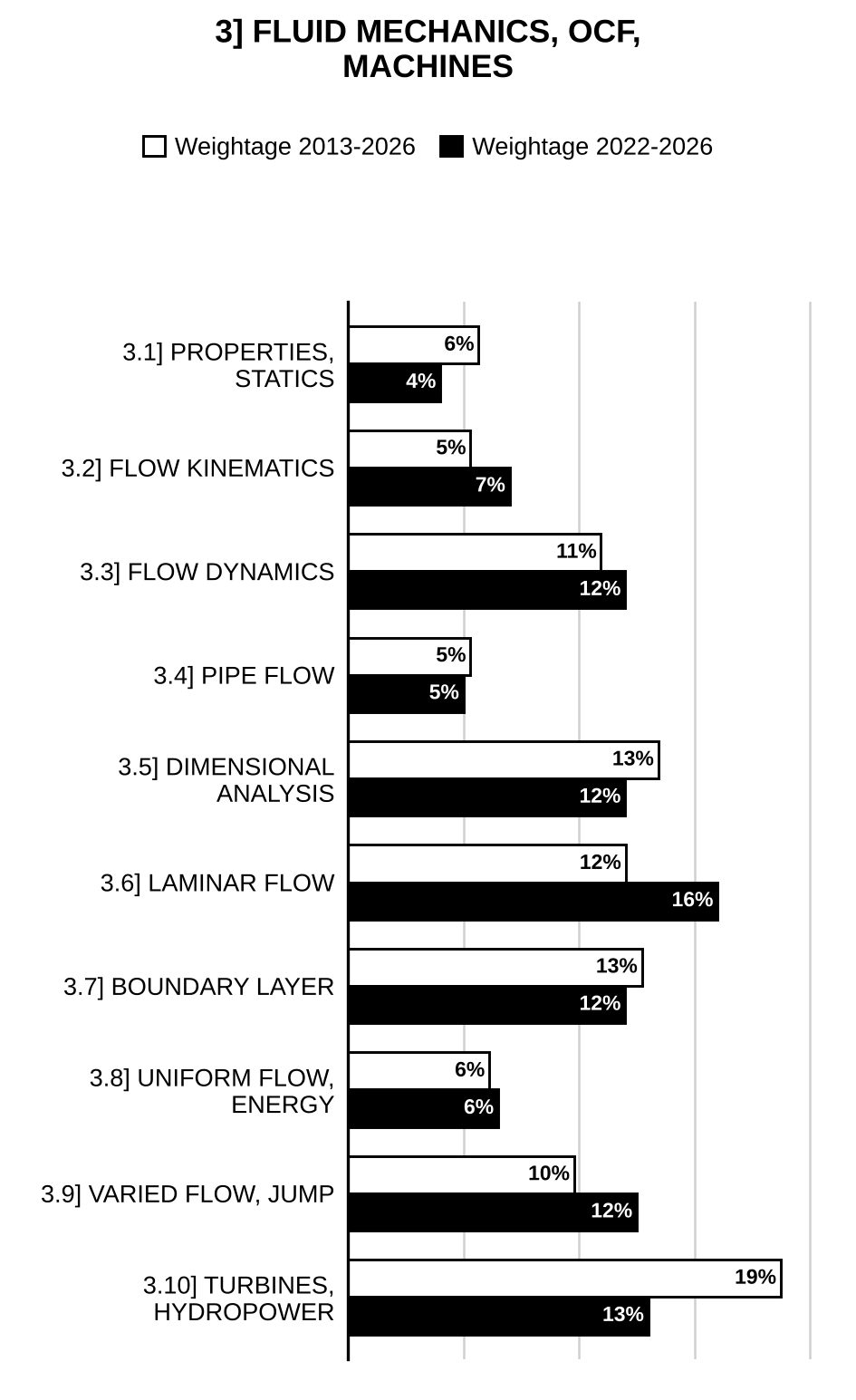
Here are all 156 Fluid Mechanics, Open Channel Flow and Hydraulic Machines questions asked in UPSC Civil Engineering Optional Paper I from 2004 to 2026, arranged under the 10 topics of the official syllabus. Within each topic the latest questions come first.
Each question ends with a code such as [2024/15m/3b] – the year, the marks, the word limit (where UPSC set one) and the question number in the paper.
3.1] Fluid properties and fluid statics
13 questions
A rigid body having dimensions of 0.6 m wide, 0.9 m high and 1.2 m long weighs 10 kN when submerged in water. What will be its weight and density in air? (Assume specific weight of water as .) [2025/10m/5a]
A 125 mm diameter vertical cylinder rotates concentrically inside a fixed cylinder of diameter 130 mm. Both cylinders are 325 mm long. Find the dynamic viscosity of the liquid that fills the space between the cylinders, if a torque of 0.92 Nm is required to maintain a speed of 70 r.p.m. [2024/10m/5a]
A space 25 mm wide between two large plane surfaces is filled with glycerine. What force is required to drag a very thin plate in area between the surfaces at a speed of 0.5 m/s: (i) if this plate remains equidistant from the two surfaces, (ii) if it is at a distance of 10 mm from one of the surfaces? Take dynamic viscosity of glycerine . [2021/10m/1d]
A 1.5 cm wide gap between two vertical plane surfaces is filled with an oil of specific gravity 0.9 and dynamic viscosity . A metal plate 1.0 m × 1.0 m × 0.1 cm thick and weighing 20 N is placed midway in the gap. Find the force required if the plate is to be lifted up with a constant velocity of 0.1 m/s. [2020/10m/1d]
An inclined tube reservoir manometer is constructed as shown. Derive a general expression for the liquid deflection, , in the inclined tube, due to the applied pressure difference, .
[Figure: Reservoir of diameter D containing gauge liquid of density , with pressure difference Δp applied at its top; an inclined tube of diameter d rises from the bottom of the reservoir at angle θ to the horizontal. Dashed line: equilibrium liquid level. Under Δp the reservoir level (1) falls by and the liquid in the inclined tube moves a distance L along the tube to level (2), a vertical rise above the equilibrium liquid level.] [2018/15m/2c]
A vertical isosceles triangular gate with its vertex up has a base width of 2 m and a height of 1.5 m. If the vertex of gate is 1 m below the free water surface, find the total pressure force and the position of centre of pressure. [2017/10m/1a]
A cylindrical gate shown in Fig. 6(b) is 5 m in diameter and 20 m long. Find the total pressure on the gate in magnitude and direction.
[Figure: Fig. 6(b) – Cylindrical gate of diameter 5 m (marked along an inclined diameter) resting on two short inclined hatched seats on either side of its lowest point A. Water on the left side of the gate between a horizontal bed line at the level of A and a free surface level with the top B of the gate (water depth 5 m, dimensioned from the bed at A to the level of B). B is the top and A the bottom of the vertical diameter (dashed); C is the left end of the horizontal diameter.] [2014/15m/6b]
An open cylinder of 40 cm diameter and 90 cm height is with water level upto 40 cm. If the cylinder is rotated at 160 r.p.m. about its axis, calculate the pressure head (i) at the bottom of the cylinder at edge and (ii) at the centre of the cylinder at bottom. [2011/12m/1d]
A vertical rectangular gate is 3.0 m high and 2.0 m wide. It is hinged at the top. If the water is standing upto a depth of 1.5 m above the top edge of gate on one side, determine the force required at the lower edge of the gate so that gate remains closed.
[Figure: Vertical gate 3.0 m high with a hinge at its top edge; free water surface (∇) on the left side 1.5 m above the hinge; resultant water pressure force P acting horizontally on the gate from the water side (towards the right); force F (Force) applied horizontally at the lower edge of the gate acting towards the water side (to the left)] [2011/12m/1e]
A masonry dam of rectangular section, 20 m high and 10 m wide, has water up to a height of 16 m on its one side. Determine (i) pressure force due to water on one metre length of the dam, (ii) position of the centre of pressure and (iii) the point at which the resultant cuts the base. Assume density of masonry = and density of water = . [2010/10m/5b]
A trapezoidal masonry dam, having 4 m top width, 8 m bottom width and 12 m height, is retaining water up to a height of 10 m. The density of the masonry is and coefficient of friction between the dam and soil is 0.55. The allowable compressive strength stress is . Check the stability of the dam. [2010/30m/8a]
A gate of size 2 m × 1 m can slide without friction. It is held in place by a thin cable which pulls it to the left due to buoyancy on a balloon of diameter and of negligible weight. The gate just opens when the level of water is as shown in the figure below. Obtain . Where should the cable be attached so that the gate slides smoothly (i.e., without rotation) inside the channel?
[Figure: Water on the left held by a vertical wall; a horizontal channel leads off to the right through the wall, its opening 2 m high closed by a vertical gate 2 m × 1 m sitting in the opening; the free water surface is 3 m above the top of the channel opening. A spherical balloon of diameter D floats submerged in the water to the left; a cable runs vertically down from the balloon to a pulley near the level of the gate and then horizontally to the gate. Labels: Balloon, Cable, Pulley, Water, Gate 2 m × 1 m, Channel] [2009/12m/1d]
An open circular cylindrical vessel of 20 cm diameter and 80 cm height contains water up to a height of 60 cm. Find the maximum rotational speed of the cylindrical vessel about its vertical axis so that no water spills. The vortex flow developed in the circular vessel is forced-type vortex. [2009/12m/1e]
3.2] Kinematics of fluid flow
10 questions
What is the significance of curves of constant stream function (CSF)? Explain why the stream function is useful in fluid mechanics. [2026/5m/8c(ii)]
The stream function for a two-dimensional flow is given by . Calculate the velocity and velocity potential at point . [2024/15m/6b]
A two-dimensional incompressible flow field is given by , where and are the unit vectors along x and y axes, respectively. Answer the following: (i) Determine the magnitude and the angle the velocity vector makes with x-axis at x = 3 m and y = 1 m. (ii) Is the flow physically possible? If so, determine an expression for stream function. (iii) What is the discharge between the streamlines passing through (1, 0) and (0, 1)? (iv) Is the flow irrotational? Justify your answer with appropriate reasons. [2023/15m/6b]
In a flow field, the following velocity components are given: and Show that the flow is possible. Obtain the relevant stream function. [2019/10m/1d]
For a two-dimensional irrotational flow in the x-y plane, the velocity component in the x-direction is given by . Obtain expressions for the stream function and the velocity potential , if it is given that for and at the origin. What type of flow pattern is represented by this? [2016/10m/1a]
At the entry of the pump intake the velocity v varies inversely as the square of the radial distance r from inlet to suction pipe. The velocity is found to be 0.8 at a radial distance of 1.5 m. Compute the acceleration of flow at radial distances of 0.5 m and at 1.25 m, from the inlet assuming the stream-lines to be radial. [2015/10m/1e]
Define Eülerian method of fluid motion. State the various types of fluid flow. Explain (i) uniform and non-uniform flow, and (ii) laminar and turbulent flow. [2014/10m/5d]
If the velocity components of two-dimensional flow are and Obtain: (i) Stream function – . (ii) Discharge passing between two points (2, 3) and (3, 4). [2011/12m/1c]
The expression for stream function is described by . Indicate whether the flow is rotational or irrotational. Determine the value of velocity potential , if it exists. [2010/15m/2b]
If the velocity components for possible flow are given as determine whether or not fluid motion is possible. Obtain stream function, . Show whether the flow is rotational or irrotational. If irrotational, find velocity potential, . [2009/10m/2c(i)]
3.3] Dynamics of fluid flow
23 questions
A free jet of water with constant cross-section area of is deflected by a hinged plate of length 2.0 m, supported by a spring with spring constant N/m and uncompressed length m as shown in the figure. If the density of water is and the deflection angle is , determine the jet velocity. Assume steady-state condition and neglect the weight of fluid and the weight of the plate within the control volume considered in this case:
[Figure: A horizontal jet (from the left) strikes a plate hinged at its lower (left) end on the ground; the plate is inclined at angle to the horizontal and the water leaves along the plate upwards with velocity ; the plate is supported from below by a vertical spring ( = 500 N/m, = 1.0 m) mounted on a roller carriage on the ground.] [2026/10m/5a]
Water flows from A to B through a tapering pipe. The following data is given at section A and B:
| Section | A | B |
| Diameter of pipe | 12 cm | 10 cm |
| Elevation | 100.000 m | 101.000 m |
| Gauge pressure | 30 kPa | 20 kPa |
Estimate the discharge in the pipe line. (Assume zero loss of energy between two sections.) [2025/10m/7c(ii)]
The flow of water in a canal varies from 425 l/s to 680 l/s. It is desired to discharge not less than 340 l/s of water and not more than 425 l/s over a 90° V-notch weir into one channel, while the remainder goes over a sharp-crested rectangular weir. Find the length of rectangular weir and maximum head on each weir. Take for both weirs. [2024/20m/7c]
Water at 20°C flows through a pipe of inlet diameter of 10 cm and passes further through a circular nozzle of diameter 2.5 cm, exits into the air as a jet, and strikes a vertical plate as shown in the figure. A force, F = 100 N is required to hold the plate stationary. Assuming steady, frictionless, one-dimensional flow and densities of water and mercury as 1000 kg/m³ and 13550 kg/m³ respectively, answer the following: (i) Determine the velocities at sections ① and ②. (ii) Determine the mass flow rate of water. (iii) Determine the mercury manometer reading ‘h’.
[Figure: Horizontal pipe carrying water at 20°C: section ① of diameter cm, followed by a converging nozzle to section ② of diameter cm; the free jet leaving the nozzle strikes a vertical plate normally and spreads up and down along it; the plate is held by a horizontal force F acting against the jet. A U-tube mercury manometer is connected between pressure taps at sections ① and ②; manometer deflection h.] [2023/20m/8c]
A certain fluid is flowing through the pipe bend as shown in the figure below. Determine the forces exerted by the pipe boundary on the fluid, if given that bar (gauge), m/s, m, m, and .
[Figure: Reducing pipe bend laid horizontal: flow enters horizontally from the left at section 1–1 (diameter ) and leaves at section 2–2 (diameter ), the outlet axis being turned through from the inlet direction. (Laid horizontal)] [2020/15m/4b]
A rectangular weir of crest width 0.4 m is used to measure the discharge in a rectangular channel 0.6 m wide and 0.45 m deep. If the water level in the channel is 0.225 m above the crest, find the discharge in the channel. Velocity of approach to be considered. Assume . [2019/15m/4c]
A 0.3 m diameter pipe carries water at a velocity of 24.4 m/s. At points and , the pressures were measured 361 kPa and 288 kPa respectively. The elevations of points and were as 30.5 m and 33.5 m respectively. Find the loss of head between and . [2017/15m/2a]
A 5 mm diameter nozzle is discharging a vertically upward jet of water with a velocity of 10 m/s at the nozzle. What is the maximum height to which this jet will reach? If a flat plate weighing 1.5 N is balanced on the jet, what will be its height from the nozzle? [2016/10m/5b]
For the sluice gate shown in Figure, if and , what is the height of the opening? Given , . Also determine the flow per unit width.
[Figure: Vertical sluice gate in a horizontal channel; upstream depth 2 m with velocity head above the water surface; gate opening a; downstream (contracted) depth 0.8 m with velocity head ; total energy line shown dashed] [2015/5m/7a(i)]
A pipe of 40 cm diameter is carrying water. The pipe is bent by 145 degrees from the horizontal counter-clockwise. The pressure of water flowing through the pipe is . Find the magnitude and direction of the resultant force on the bend. [2014/10m/1e]
Write the Navier-Stokes equation in Cartesian coordinates for incompressible fluid. [2014/5m/6c(i)]
A body is immersed in an air stream with an ambient velocity of 40 m/s at a pressure of and a mass density of . If the velocity of the immersed body is 80 m/s at some point, determine the pressure at that point. [2013/10m/1c]
A 2.5 cm diameter water jet strikes a stationary plate held at right angles to the jet. The jet exerts a force of 784.53 N on the plate. Determine the discharge. Assume the mass unit weight of water as . [2013/10m/1d]
A pipeline carrying oil of specific gravity 0.8 changes in diameter from 300 mm at position to 500 mm diameter at position , which is 5 m at a higher level. If the pressure at is and at is , and the discharge is , determine the loss of head and the direction of the flow. [2012/12m/1d]
Derive Euler’s equation of motion along a streamline for an ideal fluid flow stating clearly the assumptions. Explain how this is integrated to get Bernoulli’s equation along a streamline. How is this equation modified while applying in practice? Draw a relevant sketch pertaining to Bernoulli’s equation components for flow in an upward inclined converging pipe. [2012/15m/3c]
A jet of water of diameter 100 mm strikes a curved vane at its centre with a velocity of 15 m/s. The curved vane is moving with a velocity of 7 m/s in the direction of the jet. The jet is deflected through an angle of 160°. Assuming the vane is smooth, find– (i) the force exerted on the vane in the direction of the jet; (ii) the power of the jet; (iii) the efficiency. A series of vanes are attached to a rotating wheel such that jet always strikes the vane. Find (i), (ii) and (iii) of the above case for this situation also. [2012/15m/4c]
A liquid of specific gravity 1.6 is flowing upwards at the rate of through a vertical venturi meter with an inlet diameter of 0.3 m and throat diameter of 0.15 m. The coefficient of discharge is 0.98. The vertical distance between the pressure tappings is 0.5 m. (i) Find the difference in readings of the two pressure gauges, which are connected to the two pressure tappings. (ii) Find the difference in levels of mercury columns of the differential manometer connected to the tappings in place of pressure gauges. (iii) Sketch the arrangement showing the details. [2012/15m/4d]
A Pitot tube was used to measure the quantity of water flowing in a pipe of 0.3 m diameter. The water was raised to a height of 0.25 m above the centre of pipe in a vertical tube. If the mean velocity is 0.78 times the velocity at the centre and the coefficient of Pitot tube is 0.98, find the quantity of water in litre per second. Static pressure head at the centre of the pipe is 0.2 m. [2010/10m/1d]
A water wheel has a number of hemispherical vanes equally spaced on the periphery. A jet of diameter of 300 mm having a velocity of 16 m/sec impinges on the vanes which have tangential velocity of 6 m/sec. Determine the work done on the wheel. [2010/10m/1f]
A rapid stream has a depth of flow 1 m and velocity of flow 3.7 m/sec. Find the height of suppressed diversion weir which would be constructed across stream to raise the water level on the upstream to a depth of 3 m. Take coefficient of discharge for free weir = 0.58 and for submerged portion of weir as 0.8. [2010/15m/2c]
In a free cylindrical vortex of water, the tangential velocity at radius of 0.1 m from the axis of rotation is found to be 10 m/sec and the intensity of pressure is . Find the pressure intensity at a radius of 0.2 m from the axis. [2010/15m/3b]
A pipe carrying oil of specific gravity 0.877 changes in size from 0.15 m at section to 0.45 m at section . Section is 3.6 m lower than section and pressures are and respectively. If the discharge is , determine the head loss and the direction of flow. Find the force acting on the conical portion of the pipe. Neglect the weight of water and the pipe. [2010/15m/4b]
Find the discharge of water through a horizontal venturimeter having 400 mm diameter at the inlet main and 150 mm diameter at the throat, if the differential gauge between the inlet and its throat shows a pressure head of 25 cm of mercury. Assume coefficient of discharge for the meter as 0.98 and the specific gravity of mercury as 13.6. [2004/12m/1d]
3.4] Pipe flow
12 questions
Prove that the power transmission through nozzle is maximum when . Neglect the minor losses.
[Figure: A pipe of diameter and length leading from a reservoir (free water surface shown as a dashed line) slopes downward and ends in a nozzle of outlet diameter ; = Friction coefficient.] [2022/10m/5a]
Reservoir (elevation 65 m) is filling reservoir (elevation 110 m) and reservoir (elevation 90 m) by a pump and pipe system. The discharge to reservoir is . If the efficiency of the pump is 0.70, calculate the required power of the pump. The physical characteristics of the pipe system are given in the figure below. Neglect the minor losses. Draw the HGL and EGL:
[Figure: Three reservoirs connected through a pump at a junction. Water surface levels above the reference datum: reservoir A 65 m (lowest), reservoir B 110 m, reservoir C 90 m. Pipe from A to the pump: = 400 m, = 30 cm, = 0.02. Pipe from the pump to B: = 300 m, = 15 cm, = 0.015. Pipe from the pump to C: = 1000 m, = 20 cm, = 0.025.] [2022/15m/6c]
Water flows through a 1.0 m diameter pipe which has a roughness height, , of 0.1 mm. What will be the maximum possible flow rate if the head loss is to be limited to 5 m per km? Use the following equation for the friction factor: Symbols have their usual meanings. [2016/15m/4a]
Three pipes are connected as shown in figure. The characteristics of pipe are as follows:
| Pipe | D (mm) | L (m) | f |
| A | 150 | 600 | 0.020 |
| B | 100 | 480 | 0.032 |
| C | 200 | 1200 | 0.024 |
Determine the flow rate in each pipe. Minor losses may be neglected.
[Figure: Reservoir with water surface at 60.0 m; pipes A and B run in parallel from the reservoir to a junction P at EL 36.00; from P a single pipe C runs down and discharges freely at its outlet at EL 15.00 m] [2015/20m/3c]
A booster pump is installed in the pipeline between two reservoirs. If the energy added by the pump is 20 m, determine the flow rate in the pipeline in . Length of the pipeline = 1500 m; Coefficient of friction = 0.02; Diameter of the pipeline = 300 mm; WSEL of A = 200 m WSEL of B = 185 m.
[Figure: Reservoir A (water surface 200) on the left connected by a pipeline, with a pump in it, to reservoir B (water surface 185) on the right] [2015/5m/6b(i)]
A 900 mm diameter steel pipe conveys a discharge of . The wall thickness of the pipe is 10 mm and the elastic modulus of the pipe material is and the bulk modulus of water is . Determine the increase in pressure if the valve at the end of the 3.5 km long pipe is closed in (i) 3.5 sec and (ii) 10.0 sec. Assume the mass density of the water as . [2013/10m/3c(i)]
The difference in water surface levels in two tanks is 15 m and distance between them is 600 m. Two pipes of diameters 30 cm and 20 cm, and each having equal length, are connected to these tanks. Find the discharge through the pipes when they are connected appropriately in (i) series and (ii) parallel. The coefficient of friction = 0.04 for each pipe. Use . Find the ratio of discharges when the pipes are in parallel to when the pipes are in series. [2012/15m/2d]
Water is flowing through two pipes one of 10 mm diameter and second of 5 mm diameter and both are discharging in 12 mm diameter pipe. The rate of flow in 10 mm diameter is 1.0 c.c./s. If the Reynolds number for 12 mm diameter pipe flow is 4000, determine the rate of flow in 5 mm diameter pipe. Consider kinematic viscosity equal to . [2011/15m/4c]
A water main of concrete pipe 3200 m long, 0.3 m diameter discharges into a reservoir at the rate of litres per day. If this pipeline is gradually closed by operating a valve at the end of reservoir in 16 seconds, is there any possibility of pipe burst? The safe pressure of concrete pipe is . [2010/10m/1e]
A pipe 0.6 m in diameter takes off from a reservoir 150 m high above the datum. The pipe is 5000 m long and is laid completely at the datum level. For the last 1200 m, water is drawn by service pipes at a uniform rate of per 300 m. Find the head lost in the last 1200 m length of the pipe. Use and . Velocity is zero at the dead end. [2010/15m/3c]
Two pipes each 100 m long and diameters 50 mm and 100 mm respectively, are arranged in parallel between two reservoirs which have difference of water levels as 10 m. If friction factor for each pipe is same as , calculate the rate of flow through each pipe. Neglect minor losses. Use formula. [2009/10m/3b(ii)]
The water is flowing with a velocity of 1.5 m/s in a pipe of length 2500 m and diameter 500 mm. At the end of the pipe a valve is provided. Find the rise in pressure (i) if the valve is closed in 5 seconds. (ii) if the valve is closed instantaneously. Take value of , pipe to be rigid and bulk modulus of water . [2004/12m/1e]
3.5] Dimensional analysis and similitude
17 questions
The nominal flow rate of water over a weir is . A 1 : 10 scale model of the weir is tested in a water channel. Answer the following: (i) What is the expected flow rate for the model? (ii) If a force of 12 N is measured on the model, what force would be expected on the prototype? [2026/10m/5b]
The discharge Q over a small rectangular weir depends on head H over the weir, the weir height P, gravity g, width of the weir L and fluid properties: density , dynamic viscosity . Express the relationship between the variables in dimensionless form using Buckingham method. [2025/15m/6a]
The resistance force of a ship is a function of its length , velocity , acceleration due to gravity and fluid properties like density and viscosity . Write this relationship in a dimensionless form. [2024/15m/6a]
The flow rate of water over a weir is 3 m³/s. A 1 : 10 scale model of the weir is tested in a water channel. Answer the following: (i) What flow rate should be used for the model? (ii) If a force of 15 N is experienced on the model, what force would be expected on the prototype? [2023/10m/5a]
In a fluid machine, the torque of the impeller is known to depend on the diameter and speed of the impeller, the density and dynamic viscosity of the fluid. Obtain the relationship in a dimensionless form using Buckingham method. Specify the use of non-dimension numbers in design problems. [2022/10m/5d]
A flow meter when tested in a laboratory gives a pressure drop of for a discharge of in a 150 mm diameter pipe. If a geometrically similar model is tested in 600 mm diameter pipe at identical conditions of fluid, determine the corresponding discharge and pressure drop in the model. [2021/10m/5d]
The drag of a sonar transducer is to be predicted, based on wind tunnel test. The prototype, a 0.3 m diameter sphere, is to be towed at 2.57 m/s in sea water at 4.5°C. The model is 152 mm in diameter. Determine the required test speed in air. If the drag of the model at these test conditions is 2.7 N, estimate the drag of the prototype. Given that at 4.5°C, , and at STP, , . [2020/10m/5d]
The pressure drop generated by a pump depends on impeller diameter , the rotational speed , fluid discharge , the fluid density and viscosity . Using Buckingham -theorem, obtain dimensionless form of the functional relationship. [2019/15m/2b]
The drag force , on a smooth sphere depends on the relative speed , the sphere diameter , the fluid density and the fluid viscosity . Using Buckingham -theorem, obtain a set of dimensionless groups that can be used to correlate experimental data. Select the repeating parameters as , , . [2018/20m/4a]
A 1 : 50 scale spill-way model has discharge of . What is the corresponding prototype discharge? If a flood phenomenon takes 12 hours to occur in the prototype, how long should it take in the model? [2017/10m/5a]
A submarine is travelling at a large depth in the sea (seawater , ) with a speed of 5 m/s. It is desired to estimate the drag force on the submarine by conducting experiments in a freshwater tank on a scaled model of the submarine. If the length scale is 1 : 25, what should be the speed in the model? If the drag force on the model is measured as 1000 N, what is the drag force on the submarine? [2016/15m/4b]
In order to predict lift and drag forces on a scale model of an aircraft during a section of operational envelope, involves sea level flight at 100 , where the speed of sound may be taken as 340 . It is proposed to utilise cryogenic wind tunnel with Nitrogen at 5 atmosphere of pressure and a temperature of –90°C (, viscosity Ns for nitrogen). The speed of sound in nitrogen at this temperature is 295 . Determine the wind tunnel flow velocity, the scale of model to ensure full dynamic similarity and, the ratio of forces acting on the model and prototype. Mass density of air 1.2 and viscosity Ns. [2015/15m/2c]
Prototype data of Tidal Channel are as follows: Length of channel = 18 km, Discharge = 250 ; Depth = 2.5 m, Width of the channel = 50 m. Model is built with a vertical scale of 1 : 50 and a horizontal scale of 1 : 500. Tidal period is 12 hours. Compute the average velocity in and tidal period in the model. [2015/5m/5a(ii)]
Discharge through an orifice depends on head , acceleration due to gravity , mass density , diameter of orifice and viscosity . Make out a dimensional analysis using Buckingham’s pi theorem and show that Use , and as the repeating variables. [2014/20m/8c]
A shallow river has a width of 1200 m and conveys a discharge of at a mean velocity of 0.90 m/s. It is proposed to construct a river model to a horizontal scale of 1 : 800 and a vertical scale of 1 : 40. If Manning’s for the river bed material is 0.025, what should be its value in the model? Verify whether the flow in the model is turbulent. Assume kinematic viscosity as 1.1 centi stoke. [2013/10m/3b]
If the velocity of the flow through orifice is dependent on diameter of orifice (D), head (H), and acceleration due to gravity (g), by using Buckingham’s method, frame the equation of velocity through orifice. [2011/15m/4b]
A river stretch 10 km long and 920 m wide is to be modelled for flood studies in a hydraulic laboratory where the available flume size is 2 m width, 20 m length and 70 cm height. It is decided to use a depth scale of 10. If the peak flood in the river is 3000 cumec at a depth of 6 m, find the suitable horizontal scale to be adopted for construction of the model. Maximum available flow is 150 litres/s in the laboratory. The horizontal scale should be a multiple of 10 and such that the model is as big as possible. Determine the model dimensions, depth and discharge. Assume the hydraulic depth is same as the depth of flow in both the model and the prototype. [2004/20m/3b]

Preparing for Prelims too?
Our UPSC Prelims Topic-wise PYQ eBook covers every Prelims question with detailed explanations, so you can see exactly where UPSC asks from.
View the BookDownload Free Sample3.6] Laminar flow
12 questions
Oil of specific gravity of 0.8 and kinematic viscosity of is pumped at a rate of through a 150 mm diameter, 325 m long pipe. Determine the Reynolds’ number, pressure drop, average shear stress at the pipe wall and power required to maintain flow under the following conditions: (i) If the pipe is horizontal (ii) If the pipe is inclined at 10° with the horizontal and the flow is in the upward direction. [2026/20m/7c]
A liquid whose specific gravity is 0.8 and dynamic viscosity is 1.8 poise, flows in a vertical pipe of 8 cm diameter. Pressure gauges in the pipe located 20 m apart indicate a pressure of 180 kPa at the upper end and a pressure of 360 kPa at the lower end. Calculate the flow rate and find the direction of the flow in the pipe. (Use Hagen-Poiseuille equation.) [2025/10m/7c(i)]
A large tank as shown in the above figure has a vertical pipe 70 cm long and 2 cm in diameter. The tank contains an oil of density 920 kg/m³ and viscosity 1.5 poise. Find the discharge through the pipe when the height of the oil level of the tank is 0.80 m above the pipe inlet.
[Figure: Large tank containing oil, free surface (level Ⓐ) 80 cm above the bottom of the tank where the vertical pipe begins; vertical pipe of diameter 2 cm and length 70 cm discharging (Q) downward at its outlet (level Ⓑ).] [2024/10m/5c]
Glycerin is flowing through a 2.5 cm diameter horizontal pipe of 30 m length that discharges it into the atmosphere at 101 kPa. The flow rate through the pipe is 0.05 litres/second. Dynamic viscosity () and density of glycerin are 0.25 kg/m-s and 1250 kg/m³, respectively. Answer the following: (i) What is the absolute pressure at 30 m length just before the exit of pipe? (ii) At what angle () must the pipe be inclined downward from the horizontal for the pressure in the entire pipe to be atmospheric pressure and the flow rate to be maintained the same? [2023/20m/7c]
Two parallel plates are moving in opposite direction with velocities 1 m/s and 2 m/s respectively. For the given coordinate system (shown below), draw the velocity and shear stress profile for positive and negative pressure gradient after obtaining the profile equations:
[Figure: Two parallel horizontal plates a distance apart; the -axis lies along the mid-plane, -axis vertical. Plate 1 at moves in the direction with = 1 m/s; Plate 2 at moves in the direction with 2 m/s. Distances and marked from the mid-plane to each plate.] [2022/20m/7b]
Two parallel plates kept 0.10 m apart have laminar flow of oil between them with a maximum velocity of 1.5 m/s. Calculate the discharge per metre width, the shear stress at the plates, the difference in pressure between two points 20 m apart, the velocity gradients at the plates and velocity at 0.02 m from the plate. Take viscosity of oil to be . [2021/15m/4b]
An oil of viscosity 18 poise flows between two horizontal fixed parallel plates which are kept at a distance 150 mm apart. The maximum velocity of flow is 1.5 m/s. Find: (i) Pressure gradient (ii) Shear stress at two horizontal parallel plates (iii) Discharge per unit width for laminar flow of oil. [2020/15m/8b]
The velocity distribution for the flow of a Newtonian fluid between two fixed wide, parallel plates is given by the following equation: where is the mean velocity. If the fluid viscosity is , and , determine (i) the shearing stress acting on the bottom wall, and (ii) the shearing stress acting on a plane parallel to the wall and passing through the centre line (mid-plane).
[Figure: Two fixed parallel plates a distance 2h apart (h above and h below the centre line); x-axis along the centre line, y measured upwards from it; parabolic velocity profile u, maximum at the centre line and zero at both walls.] [2018/10m/1d]
An oil of dynamic viscosity 1.5 poise and relative density 0.9 flows through a 3 cm diameter vertical pipe. Two pressure gauges are fixed 20 m apart. The gauge fixed at the top records 200 kPa and gauge fixed at the bottom records 500 kPa. Find the direction of flow and the rate of flow. [2017/20m/3b]
Steady, two-dimensional, fully developed laminar flow of a fluid (mass density , dynamic viscosity ) is taking place on an infinite plate inclined at an angle of 30° from the horizontal. The thickness of the fluid layer is h and the top surface has atmospheric pressure. Obtain an expression for the average flow velocity in the direction of flow. [2016/15m/3c]
Determine the diameter of the vertical pipe needed for a flow of a liquid of kinematic viscosity at a Reynolds number of 1500. The constant pressure is maintained throughout its length. [2015/5m/5a(i)]
For steady laminar flow between two infinitely wide stationary plates, , and pressure gradient , determine discharge per unit width , maximum shear and maximum velocity. [2014/10m/6c(ii)]
3.7] Boundary layer, drag and lift
18 questions
Assuming the law for the velocity distribution in the boundary layer as , derive an expression for the thickness of boundary layer. Hence calculate the thickness of boundary layer at a point 2.5 m from the leading edge of a plate, if the size of the plate is 3.0 m long and 1.25 m wide, and it is immersed in the water moving at a velocity of 0.3 m/s. Take viscosity of water equal to . [Notations used in the above expression have their usual meanings]. [2026/15m/6a]
With neat sketches explain Hydrodynamically smooth surface, Hydrodynamically rough surface and Boundary layer separation. What are the effects of separation in a fluid flow problem? [2025/10m/5b]
Calculate the friction drag on a flat plate 15 cm wide and 45 cm long placed longitudinally in a stream of oil of relative density 0.925 and kinematic viscosity 0.9 stoke, flowing with a free stream velocity of 6 m/s. Also find the thickness of the boundary layer and shear stress at the trailing edge. Take density of water 1000 kg/m³. [2024/10m/5b]
A rectangular wing on a small airplane has a 1.3 m chord and a 10 m span. When flying in air at 250 km/hour, the wing experiences a total aerodynamic force of 20 kN. If the lift to drag ratio is 3, what would be the lift coefficient of the wing? Take density of air as 1.20 kg/m³. [2023/10m/5b]
The velocity profile in a laminar boundary layer on a flat plate is modelled by the cubic expression = velocity at a distance from the surface of the plate, = main stream velocity. Evaluate all the constants in terms of boundary layer thickness. Draw the velocity distribution and stress distribution curves. Indicate the application and significance of boundary layer. If the plate is moving with a velocity of 2 m/s in positive -direction, what will be the velocity distribution curve? [2022/15m/6a]
A submarine can be assumed to have cylindrical shape with rounded nose. Assuming its length to be 55 m and diameter 6.0 m, determine the total power required to overcome boundary friction if it propels at the velocity of 8.0 m/s in sea water at 20°C. Take mass density of sea water at 20°C as and kinematic viscosity of sea water at 20°C as . [2021/15m/6a]
Find expression for boundary layer thickness (), shear stress () and average coefficient of drag () in terms of Reynolds number, if velocity profile of laminar boundary layer is given as: [2020/15m/6a]
The velocity profile over a horizontal flat plate held in a free stream with a velocity U is given by Evaluate the constants A, B and C. [2019/10m/5c]
A cylindrical chimney 1 m in diameter and 25 m tall is exposed to a uniform 50 km/h wind at standard atmospheric conditions. End effects and gusts may be neglected. Estimate the bending moment at the base of the chimney. Given: , , ,
[Figure: Vertical cylindrical chimney of diameter d = 1 m and height L = 25 m standing on the ground; the resultant drag force acts horizontally at height L/2.] [2018/15m/6b]
A laboratory wind tunnel has a test section that is 305 mm square. Boundary-layer velocity profiles are measured at two cross-sections and displacement thicknesses are evaluated from the measured profiles. At section (1), where the free stream speed is , the displacement thickness is . At section (2), located downstream from section (1), . Calculate the change in static pressure between section (1) and section (2). Express the result as a fraction of the free stream dynamic pressure at section (1). Assume standard atmospheric conditions. [2018/15m/7c]
Air flows over a flat plate 1 m long at a velocity of 6 m/sec. Determine (i) the boundary layer thickness at the end of the plate, (ii) shear stress at the middle of the plate, (iii) total drag per unit length on both sides of the plate. Take mass density of air and kinematic viscosity of air . [2017/15m/8b]
Flow of air (mass density 1.2 , dynamic viscosity ) takes place over a rectangular flat plate kept parallel to the flow direction. The flow velocity is 10 m/s and the length of the plate is such that the Reynolds number is critical at the trailing edge (i.e., the boundary layer is laminar throughout). The width of the plate is half of its length. The plate is then rotated by 90° in its plane so that the flow is now taking place along the shorter side. Find the ratio of the drag forces under these two flow situations. [2016/10m/8b(i)]
The wind velocities were measured above a smooth plane ground surface at 2 m and 4 m heights as 2 and 2.3 m/s respectively. Compute the shear velocity. Assume Karman’s constant as 0.40 and kinematic viscosity of air as 0.145 centi stoke. What is the velocity at 8 m above the ground surface? Calculate the probable laminar sublayer thickness. [2013/15m/2c(i)]
Distinguish between surface and form drags due to a fluid flow. Estimate the bending moment at the base of a 30 m smoke stack 2 m in diameter during a 100 km per hour wind. Assume the mass density of the air as and the kinematic viscosity as 0.15 centi stoke. [2013/10m/2c(ii)]
An expression for the velocity distribution in the boundary layer flow on a flat plate is given as where , and , and are constants. and are velocities at and respectively. is the distance measured normal to the plate and is boundary layer thickness. Value of when . Sketch the boundary layer thickness growth along the flat plate and velocity distribution in the boundary layer. Find the ratio of boundary layer thickness to displacement thickness. [2012/12m/1e]
A 2.0 m wide and 6.0 m long plate moves at a velocity of 1.75 m/s parallel to its length, through a stationary air of density and viscosity of . Determine the drag force on one side of a plate assuming (i) Laminar flow boundary layer. (ii) Turbulent flow boundary layer. [2011/15m/3c]
Find the coefficients in a cubic polynomial representing velocity profile for a boundary layer flow over a flat plate held parallel to the stream. The pressure inside the boundary layer is impressed from outside boundary layer and remains constant in the direction of flow. Find the shear stress on the plate in terms of free stream velocity, boundary layer thickness and dynamic viscosity . Cubic polynomial where , , and are coefficients and and –measured normal to the plate. [2009/12m/1f]
Explain (i) Boundary layer thickness, and (ii) Displacement thickness. The velocity distribution in a laminar boundary layer is given by where u is the velocity at a distance y from the plate, is the boundary layer thickness and U is the free stream velocity. Find the ratio of displacement thickness to boundary layer thickness. [2004/12m/1f]
3.8] Open channel flow: uniform flow and specific energy
11 questions
A venturi flume, 3.0 m wide at the entrance and 1.5 m wide at the throat, has a horizontal datum. If the depth of water at the entrance and at the throat is 0.75 m and 0.65 m respectively, calculate the theoretical discharge through the venturi flume. If a 0.2 m high streamlined hump is provided at the base so that a standing wave is formed downstream of the throat, calculate the specific energy and upstream depth for the same discharge. [2026/10m/5c]
A rectangular channel is 4.0 m wide and carries a discharge of at a depth of 1.0 m. A smooth contraction of the channel width is proposed at a section. Find the smallest contracted width that will not affect the upstream flow conditions. Neglect the energy losses in the transition. [2025/15m/6b]
A flow of 9.0 m³/s occurs in a long rectangular channel of 3.0 m width with 1.5 m depth of water flow. There is a smooth constriction in the channel to 2.0 m width in the downstream direction. Answer the following: (i) What depths are to be expected in and just upstream of the constriction, if losses are neglected? (ii) Classify the gradually varied flow profile upstream of the constriction, with proper justification. [2023/15m/6a]
A flow of 100 litres/sec flows down in a rectangular laboratory flume of width 0.60 m and having adjustable bottom slope. If Chezy’s constant (C) is 56, determine the bottom slope for uniform flow with a depth of flow 0.30 m. Also find the conveyance and state the flow. [2021/20m/2c]
A discharge of flows with a depth of 2.0 m in rectangular channel of width 4.0 m. At a downstream section, the width of channel is reduced to 3.5 m, and the channel bed is raised by 0.20 m. Analyse the water surface elevation in the transition. [2019/20m/7a]
Compute the shear stress acting on the river bed for the data given: Discharge = 5000 , River bed slope = 1 : 2500; Depth of flow = 4.50 m. Assume the river to be wide. [2015/4m/6b(ii)]
The width of a rectangular channel is 4.0 m and specific energy in the channel is 4.0 m. What would be the maximum possible discharge in the channel? [2014/10m/3b]
Water is flowing at a critical depth of flow = 1.4 m in a channel shown in the figure below. Estimate the discharge and specific energy in the channel.
[Figure: Channel section captioned “Triangular channel”, drawn as a triangle with its apex at the top: horizontal base line 2.4 m wide at the bottom, the two sloping sides converging upwards to an apex above the water surface; side slope marked 0.5 (horizontal) : 1 (vertical); water surface (∇) shown 1.4 m above the base] [2012/15m/2c]
A trapezoidal channel has a side slope of 1 : 1. It carries flow of at a velocity of 2.0 m/s. It is to be designed as most economical cross-section. Calculate the area of concrete lining for 100.0 km long channel. [2011/15m/2c]
A trapezoidal channel with one side vertical and the other sloping at two horizontal to one vertical, carries a discharge of at a mean velocity of 1.5 m/sec. Determine the longitudinal slope and channel dimensions for the best hydraulic efficiency, if Manning’s . [2009/10m/2c(ii)]
An unlined canal has its bed and side slopes composed material having mean diameter of particles 6 mm. Angle of repose of the material is 40°, the bed width of the canal is 5 m and the side slopes 1.5 (H) : 1 (V). Determine the minimum discharge that can be admitted into the canal without any sediment movement. Take bed slope 1 in 5000 and Manning’s . [2004/20m/4c]
3.9] Varied flow and hydraulic jump
14 questions
Water flows in a triangular channel having side slope 1 Horizontal : 1 Vertical and longitudinal slope of 0.001. Estimate whether the channel is mild, steep or critical sloped when a discharge of flows through it. Assume Manning’s coefficient . Also, determine for what range of depths, the flow will be on type 1, 2 and 3 curve. [2026/15m/6b]
In a horizontal, rectangular channel, the sluice gate is opened. A hydraulic jump is formed downstream of the sluice gate. The depth of water before jump is 0.8 m and specific energy before jump is 12.0 m. Find the sequent depth of the jump and energy lost in the jump. What is the initial Froude number? Classify the jump based on the results obtained in the problem. [2025/10m/8c(i)]
A flow of 9.0 m³/s occurs in a long rectangular channel of 3.0 m width with 1.5 m depth of water flow. There is a smooth constriction in the channel to 2.0 m width in the downstream direction. Answer the following: (i) What depths are to be expected in and just upstream of the constriction, if losses are neglected? (ii) Classify the gradually varied flow profile upstream of the constriction, with proper justification. [2023/15m/6a]
Draw the possible gradually varied flow profiles for critical slope. Indicate very clearly the boundary conditions. [2022/10m/5c]
A vertical sluice gate with an opening of 0.60 m produces a downstream jet with a depth of 0.40 m when installed in a long rectangular channel, 5.0 m wide, conveying a steady discharge of . It is observed that the flow, downstream of the gate eventually returns to a uniform depth of 2.5 m. Indicate whether jump will occur or not. Justify the answer. Calculate the following: (i) Energy head loss (ii) Upstream depth (iii) Force on the gate Briefly explain the applications of hydraulic jump. Can we apply critical energy concept in case of hydraulic jump? Justify your answer. [2022/20m/8b]
A hydraulic jump occurs in a triangular channel having sides sloping at 45°. Derive an equation relating two depths and the flow rate. If the depths before and after the jump in the channel are 0.5 m and 1.0 m, find out the flow rate and Froude numbers before and after the jump. [2020/20m/2c]
A rectangular channel 12.2 m wide carries of water. The slope of the channel is 0.00283. At section (1) the depth is 1.37 m and at section (2), 92 m downstream, the depth is 1.52 m. What is the average value of Manning’s roughness factor ‘n’? Take . [2018/15m/8b]
A horizontal rectangular channel 4 m wide carries a discharge of . Determine whether a jump may occur at an initial depth of 0.5 m or not. Determine the sequent depth to this initial depth. Also find the energy loss in this jump. [2017/15m/6c]
A hydraulic jump is formed in a 2 m wide rectangular channel carrying water at a flow rate of 2 . It was found that the velocity head after the jump is only 5% of that before the jump. What are the pre-jump and post-jump depths? [2016/10m/7a]
A hydraulic jump has an energy loss of 9.0 m and the downstream Froude number is 0.12. Determine the initial depth and the discharge intensity. [2015/6m/6b(iii)]
The uniform flow depth is 1.5 m in a trapezoidal channel of bottom width of 20 m with a side slope of 1(V) : 2(H). The bed slope is . Manning roughness coefficient is 0.2. The downstream control raises the water surface by 3 m. Classify the profile. [2015/5m/7a(ii)]
Following data are given for a rectangular channel: Width = 9 m, n = 0.017, ; D/S depth is 6.80 m, U/S depth is 3.6865 m; Discharge 48.748 . Using single step method compute the length of profile. [2015/5m/7a(iii)]
Draw following water surface profiles of gradually varied flow, stating conditions justifying the types of profiles: (i) type profile (ii) type profile (iii) type profile (iv) A sluice gate in a channel with mild slope to supply water in a channel from reservoir. [2011/15m/3d]
An overflow spillway as shown in the figure below is 50 m high. At the design head of 2.5 m over the spillway, find the sequent depth and energy loss in hydraulic jump formed on the horizontal apron at the toe of the spillway. Neglect energy loss over the spillway. Assume coefficient of discharge over the spillway, . Find also the percentage of energy loss occurred in hydraulic jump. Use specific energy concept to find , the supercritical depth of flow of hydraulic jump.
[Figure: Overflow spillway 50 m high above the horizontal bed/apron, with water surface 2.5 m above the crest on the upstream side. The nappe flows down the spillway face to the horizontal apron at the toe, where the supercritical depth is with velocity ; a hydraulic jump forms downstream with subsequent depth and velocity head marked above it; the energy loss is marked as the vertical distance between the upstream energy level (dashed line at the upstream water level) and the downstream energy line] [2009/20m/3c]
3.10] Hydraulic turbines and hydropower
26 questions
A Francis turbine has a speed of 300 r.p.m. The inlet diameter of the turbine is 1.20 m and its width is 280 mm at the inlet. The vane thickness coefficient can be taken as 0.95. If at the inlet, the guide vane angle is 30° and the blade angle is 90°, determine the power produced by assuming an overall efficiency of 90%. Assume radial discharge at the outlet and take density of water as . [2026/15m/8c(i)]
A Kaplan turbine develops 20,000 kW power at a head of 40 m. The diameter of the boss is 0.4 times the diameter of the runner. Calculate: (i) Diameter of the runner (ii) Rotational speed of the turbine (iii) Specific speed of the turbine (Assume a speed ratio of 2.5, flow ratio of 0.80 and an overall efficiency of 80%.) [2025/10m/5c]
A runoff river plant is proposed to generate hydroelectric power. The net head available is 30 m. The river carries a sustainable flow of in dry weather. Determine the maximum generating capacity. Daily load pattern indicates 20 hrs of average load and 4 hrs of peak load. Estimate the volume of pondage to be provided to supply the daily demand. Assume load factor = 85%, Efficiency = 80%. [2025/10m/8c(ii)]
An inward flow reaction turbine works under a head of 30 m and discharge of 10 m³/s. The speed of runner is 300 r.p.m. At the inlet tip of runner vane, the peripheral velocity of wheel is and the radial velocity of flow is , where H is the head on the turbine. If the overall efficiency and the hydraulic efficiency of the turbine are 80% and 90% respectively, determine: (i) the power developed in kw (ii) diameter and width of runner at inlet (iii) guide blade angle at inlet (iv) inlet angle at runner vane Assume that the discharge at outlet is radial. [2024/20m/8c]
An idealized radial turbine is rotating at 140 rev/min as shown in the figure. The absolute flow enters at 30° and leaves radially inward. The flow rate is 4.0 m³/s of water at 20°C. The blade thickness is constant at 10 cm. If density of water is 1000 kg/m³, what would be the theoretical power developed by the turbine?
[Figure: Radial (inward-flow) turbine runner shown as two concentric circles: outer radius 70 cm, inner radius 40 cm; blade width b = 10 cm. Absolute inlet velocity at the outer circle inclined at 30° to the tangent (horizontal dashed line); absolute outlet velocity at the inner circle directed radially inward. A curved arrow inside the runner shows the direction of rotation (clockwise as drawn, consistent with the tangential component of ).] [2023/10m/5c]
A conical draft tube having inlet and outlet diameters 1 m and 1.5 m discharges water at outlet with a velocity of 2.5 m/s. The total length of the draft tube is 6 m and 1.2 m of the length of draft tube is immersed in water. If the atmospheric pressure head is 10.3 m of water and loss of head due to friction in the draft tube is equal to 0.20 times the velocity head at outlet of the tube, find: (i) Pressure head at inlet (ii) Efficiency of draft tube. [2021/20m/3c]
A Pelton wheel develops 5520 kW power under a head of 240 m at an overall efficiency of 80% when revolving at a speed of 200 rpm. Find the unit discharge, unit power and unit speed. Assume peripheral coefficient as 0.46. If the head on the same turbine falls during summer season to 150 m, find the discharge, power and speed at this head. [2021/15m/8b]
A Pelton wheel develops 15000 kW power under a head of 250 m. Find rotational speed of wheel, number of jets required, size of each jet, dimensions of buckets and number of buckets. Given: , , , and specific speed = 30. [2020/20m/3c]
A vertical shaft Kaplan turbine operating under a head of 9.8 m has a runner diameter of 9.3 m. The turbine runs at 51.7 rpm and develops 45000 kW power by discharging of water. Determine the values of unit speed, unit discharge, unit power and specific speed of the turbine. If the critical value of cavitation coefficient for runner is 0.95, determine the location of the runner with respect to the tail water level. Assume atmospheric pressure head as 9.8 m and saturation vapour pressure head as 2.5 m. [2019/15m/8c]
A turbine develops 107 kW running at 100 rev/min under a head of 7.6 m. (i) What power would be developed under a head of 11 m assuming the same flow? (ii) At what speed should the turbine run? [2018/10m/5d]
A Pelton wheel turbine develops 5520 KW power under a head of 240 m at an overall efficiency of 80%. The turbine is running at a speed of 200 r.p.m. Find the unit discharge, unit power and unit speed assuming peripheral coefficient as 0.46. If the head on the same turbine falls during summer season to 150 m, find the discharge, power and speed for this head. [2017/20m/7a]
Why are the characteristic curves needed for a turbine? What are the various types of characteristic curves? Show a typical constant head characteristic curve between unit speed and unit power for a Pelton wheel turbine. [2016/10m/8b(ii)]
A radial flow turbine has the following dimensions: Outer periphery radius m; Inner periphery radius m. The angle made by the relative velocity at the inlet is . The width of the flow passage between the two sides of the turbine is 0.25 m. The flow of 4 goes through the turbine when the speed is 300 rpm. Find the blade angle such that water exit radially. Find the torque exerted by the water in the turbine and the power thus developed. Find the head utilised by the runner and the power resulting therefrom. Assume no shock at the entrance and blades are of negligible thickness. [2015/15m/7c]
A Kaplan turbine produces 10000 kN working under a head of 15 m at an overall efficiency of 0.86. If hydraulic efficiency = 0.9, speed ratio = 2.1, flow ratio = 0.65, diameter of boss/diameter of runner = 0.3 and , compute the following: (i) Velocity of flow, peripheral velocity, both at inlet (ii) Speed and specific speed (iii) Guide vane angle and vane tip angle at inlet Assume that the discharge is radial. [2014/20m/7c]
A pelton wheel has a mean bucket speed of 10 m/s and is supplied with water at a discharge of under a head of 40 m. If the bucket deflects the jet through an angle of 150°, find the power and efficiency of the turbine. Consider the coefficient of velocity as 0.96. [2013/10m/1e]
Following are the monthly inflow, Evaporation and rainfall data and the contemplated demand for a proposed reservoir of a hydropower project:
| Month | Jan | Feb | Mar | April | May | June | July | Aug | Sept | Oct | Nov | Dec |
| Monthly Inflow () | 50 | 40 | 30 | 25 | 20 | 30 | 200 | 225 | 150 | 90 | 70 | 60 |
| Monthly Evaporation (cm) | 6 | 8 | 13 | 17 | 22 | 22 | 14 | 11 | 13 | 12 | 7 | 5 |
| Monthly Rainfall (cm) | 1 | 0 | 0 | 0 | 0 | 19 | 43 | 39 | 22 | 6 | 2 | 1 |
| Monthly demand () | 70 | 75 | 80 | 85 | 130 | 120 | 25 | 25 | 40 | 45 | 50 | 60 |
The average reservoir area is . Estimate the storage that is necessary to meet the demand. [2013/20m/3c(ii)]
It is required to choose a suitable turbine for hydropower generation for the following data: Available head = 300 m and discharge = . A runner speed of 200 rpm and maximum overall efficiency of 85% can be adopted. Determine the diameter of the runner. Assume the specific weight of water as . [2013/12m/4c(i)]
A discharge of is to be pumped to a height of 40 m using centrifugal pumps of specific speed of 50. The pumps run at 1500 rpm and have an overall efficiency of 75%. Determine the number and arrangement of pumps. [2013/13m/4c(ii)]
An inward reaction turbine has an external diameter 1.2 m and breadth 0.3 m. If the velocity of flow at inlet is 3 m/s, find the mass of the water passing through the turbine per second. Assume 15 percent of the area of flow is blocked by blade thickness. If the speed of the runner is 240 r.p.m. and guide blade angle at inlet is 15° to the wheel tangent, draw inlet velocity triangle and find– (i) the runner vane angle at inlet; (ii) the velocity of the wheel at inlet; (iii) the absolute velocity of water leaving the guide blade; (iv) the relative velocity of water entering the runner vane. [2012/15m/3d]
A Kaplan turbine is working under a head of 75.0 m with a speed of 160 r.p.m. The rate of flow for the turbine is . The diameter of the runner is 6.0 m and diameter of hub is 3.0 m. The turbine is developing 90000 kW power. Determine: (i) Flow ratio (ii) Speed ratio (iii) Specific speed (iv) Overall efficiency. [2011/15m/2b]
A Kaplan turbine runner develops 9300 kW under a net head of 7.4 m. Mechanical efficiency of the wheel is 86%, speed ratio is 2.2 and flow ratio is 0.66. Diameter of the boss is 0.35 times the external diameter of the wheel. Determine (i) the diameter of the runner, (ii) synchronous speed and (iii) the specific speed of the runner. Assume mechanical efficiency equals to overall efficiency. [2010/15m/4c]
A model having a scale ratio of 1 : 10 is to be constructed to determine the best design of Kaplan turbine having power 7355 kW under a net head of 10 m at a speed of 100 r.p.m. If the net head available at laboratory is 6 m and the model efficiency is 88%, find– (1) the speed of the runner required in the laboratory; (2) the output power of the model; (3) the specific speed in each case; (4) the discharge needed in the model. [2009/10m/3b(i)]
A run-of-river hydroelectric power station is proposed across a river at a site where net head available is 20 m on turbine. The river carries sustained minimum flow of in dry weather and behind the power station, sufficient pondage is provided to supply daily peak load of demand with a load factor of 70%. Assuming the plant efficiency of 55%, determine the maximum generating capacity of the generator to be installed at the powerhouse. If the daily load pattern indicates 21 hours of average load and 3 hours of peak load, determine the volume of pondage to be provided to supply daily demand. [2009/12m/4c(i)]
At a proposed hydroelectric station, the available head is 80 m and it is estimated that 36000 litres per second of water is available throughout the year for operating turbines. The turbines are to run at 500 r.p.m. and the overall efficiency is 85%. The specific speed of the turbines is nearly 180. Determine the maximum available power and the number of turbines required. [2009/8m/4c(ii)]
A Pelton wheel has a mean bucket diameter of 1 m and is running at 1000 rpm. The net head on the Pelton wheel is 700 m. If the side clearance angle is 15° and discharge through the nozzle is , find (i) power available at the nozzle, and (ii) hydraulic efficiency of the turbine. Take . [2004/20m/2c]
A centrifugal pump has an impeller of 0.5 m outer diameter and when running at 600 rpm discharges at the rate of 8000 litres/minute against a head of 8.5 m. The water enters the impeller without whirl and shock. The inner diameter is 0.25 m and the vanes are set back at the outlet at an angle of 45° and the area of flow which is constant from inlet to outlet of the impeller is . Determine (i) manometric efficiency of the pump, (ii) the vane angle at inlet, and (iii) the least speed at which the pump commences to work. [2004/20m/3c]

Strengthen your GS papers
Our UPSC Mains Topic-wise & Year-wise PYQ eBook (2013–2026) maps every GS question to the syllabus, so you know what UPSC asks and how often.
View the BookDownload Free Sample« Previous: Design of Structures: Steel, Concrete and Masonry Structures | Next: Geotechnical Engineering »
Back to: Civil Engineering Optional PYQs – Topic-wise
Last updated: 30 October 2026